1
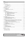
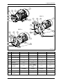
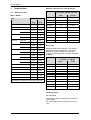
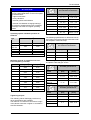
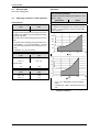
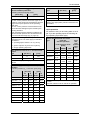
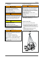
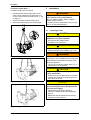
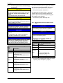
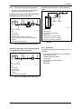
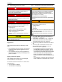
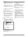
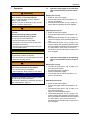
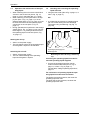
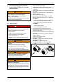
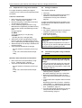
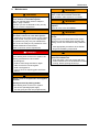
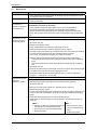
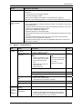
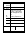
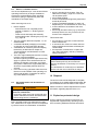
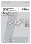
Edition: 03.2010 · 610.44440.40.000 Original operating instructions · English Operating instructions L-BV2, L-BV5 2BV2 06. 2BV2 07. 2BV5 11. 2BV5 121 2BV5 131 2BV5 161 2BV5 41. 2BV5 421 2BV5 47. L-Serie L-Series Flüssigkeitsring Liquid Ring Contents Contents Layout of the units .............................................................................................................................. 3 1 Safety ..................................................................................................................................................4 1.1 Definitions .................................................................................................................................4 1.1.1 Warning symbol............................................................................................................4 1.1.2 Key word ......................................................................................................................4 1.2 General safety instructions .......................................................................................................4 1.3 Other risks.................................................................................................................................6 2 Correct use of the equipment ..............................................................................................................6 3 Technical data .....................................................................................................................................8 3.1 Mechanical data ........................................................................................................................8 3.2 Electrical data..........................................................................................................................10 3.3 Operating conditions normal operation ...................................................................................10 4 Transport ...........................................................................................................................................13 5 Installation .........................................................................................................................................14 5.1 Installing the unit .....................................................................................................................14 5.2 Mechanical connection of the unit...........................................................................................15 5.2.1 Connecting the suction and discharge connections...................................................16 5.2.2 Making the operating-liquid connection......................................................................16 5.2.3 Connecting up system components ...........................................................................17 5.2.4 Ancillaries ...................................................................................................................17 5.3 Connecting the electric motor .................................................................................................18 5.3.1 Connection to the motor terminal box ........................................................................18 5.3.2 Operation with a frequency converter ........................................................................19 6 Commissioning ..................................................................................................................................19 6.1 Preparation of the unit.............................................................................................................19 6.2 Start-up of unit with operating-liquid supply ............................................................................20 6.3 Start-up of unit with self-suction of operating-liquid ................................................................20 6.4 Checking the direction of rotation ...........................................................................................20 7 Operation...........................................................................................................................................21 7.1 Operation with supply of the operating-liquid, automatically controlled operation..................21 7.2 Operation with supply of the operating-liquid, non-automatic control of operation.................21 7.3 Operation with self-suction of the operating-liquid..................................................................22 7.4 Checking and correcting the operating-liquid flow-rate...........................................................22 8 Decommissioning the machine and shutting it down for a longer period of time..............................23 8.1 Draining down .........................................................................................................................23 8.2 Preparations for long-term shutdown......................................................................................24 8.3 Storage conditions ..................................................................................................................24 8.4 Commissioning after a long shutdown period .........................................................................24 9 Maintenance ......................................................................................................................................25 9.1 Maintenance............................................................................................................................26 9.2 Repairs / Troubleshooting .......................................................................................................27 9.3 Service / Customer service .....................................................................................................29 9.4 Decontamination and declaration of Clearance......................................................................29 10 Disposal.............................................................................................................................................29 11 Explosion-protected design ...............................................................................................................29 EU declaration of conformity ............................................................................................................ 30 Form for statement on safety ........................................................................................................... 31 © 2009 Gardner Denver Deutschland GmbH · Industriestraße 26 · 97616 Bad Neustadt · Germany Replication, distribution and / or editing of this document and the use and distribution of its content is prohibited unless explicitly permitted. Violation obligates compensation for damages. All rights reserved in case of the issue of a patent, utility patent or design patent. Layout of the units Layout of the units 2BV2 0.. 1 7 8 9 6 2BV5 1.. 5 7 8 1 9 2 4 6 5 2BV5 4.. 2 7 8 9 4 3 1 6 2 4 610.44440.99.B01…B03 Fig. 1: Layout of the units Item Designation 2BV2 … 2BV5 1.. 2BV5 4..-.F 2BV5 4..-1G — 2BV5 110-….2-.S 2BV5 121-….2-.S — — 1 Terminal box 2 Mounting feet 3 Intermediate plates 4 Drain tapping(s) G 1 /4 G 3 /8 G 3 /8 G 3 /8 5 Anti-cavitation connection G 3 /8 G 3 /8 — — 6 Operating-liquid connection G 3 /8 G 3/4 ODER Flange (stainless steel) G 3 /8 G 3 /8 7 Discharge connection Threaded Flanged Flanged Threaded 8 Inlet connection Threaded Flanged Flanged Threaded 9 Direction of rotation arrow © Gardner Denver Deutschland GmbH 3 / 32 610.44440.40.000 Safety 1 Safety 1.1 CAUTION Definitions The following key words and symbols are used to impart warnings, important information and notes in these operating instructions: Danger of material damage. Indication of a possible danger which could lead to material damage if the appropriate precautions are not observed. CAUTION 1.1.1 Indication of a possible disadvantage, i.e. undesired circumstances may arise if the appropriate precautions are not observed. Warning symbol The warning symbol is depicted in the safety instructions in the related title frame on the left next to the key word (DANGER, WARNING, CAUTION). Safety instructions and warning symbols indicate danger of personal injury. Please follow these safety instructions to protect yourself against injury or death! Safety instructions without warning symbols indicate danger of material damage. NOTE Indicates a possible advantage, if the appropriate precautions are observed; tip. 1.2 General safety instructions WARNING 1.1.2 Key word DANGER The key words are in the title frame in the safety instructions. WARNING They follow a defined hierarchy and CAUTION they indicate (in connection with ATTENTION the warning symbol, see chapter 1.1.1) the importance of the NOTE danger or the nature of the instruction. Refer to the following clarifications: DANGER Danger of personal injury. Indication of an immediately threatened danger which could lead to death or serious injury if the appropriate precautions are not observed. WARNING Danger of personal injury. Indication of an immediately threatened danger which could lead to death or serious injury if the appropriate precautions are not observed. CAUTION Danger of personal injury. Indication of a possible danger which could lead to medium or light injury if the appropriate precautions are not observed. 610.44440.40.000 Improper handling of the unit can result in serious or even fatal injuries! This operating manual must be read and understood before commencing any work on or with the unit, and must be complied with and must be available at the unit's location WARNING Improper handling of the unit can result in serious or even fatal injuries! Operate the unit for the purposes specified under "Correct use of the equipment", page 6! using the media specified under "Correct use of the equipment", page 6! using the values specified under "Technical data", page 8! WARNING Improper handling of the unit can result in serious or even fatal injuries! Only trained and responsible specialist personnel may work on or with the unit (transport, installation, commissioning, shutdown, maintenance, disposal)! 4 / 32 © Gardner Denver Deutschland GmbH Safety WARNING Working on the unit involves a risk of injury, e.g. through cutting / shearing, squashing and burning! First get personal protection gear (helmet, gloves, safety shoes) WARNING Hazard presented by rotation of the unit's impeller! Operate the unit only if the cover is fitted! Removal of the cover is forbidden! and only then work on the system! WARNING Hair and clothing can be drawn into the unit or caught or wound in by moving parts! Do not wear any large or loose items of clothing! If you have long, loose hair, wear a hair net! DANGER Electrical hazard! Before starting work on the unit or system, the following precautions are to be taken: De-energize it. Protect it from being switched on again. Make sure that it is de-energized. Earth it and bypass it. Cover or block off adjoining parts which are still live. DANGER Electrical hazard! Work on electrical equipment must be performed by specialist electricians! DANGER Electrical hazard! First check that it is de-energized. Then open the motor terminal box! WARNING Hazard in case of overpressure and negative pressure! Hazard presented by leaking media! Hazard presented by rotation of the unit's impeller! Operate the unit only with the piping / hoses connected up to the suction and discharge connections and to the operating-liquid connection! WARNING Hazard of cutting or severing of limbs by the unit's impeller! Do not reach inside the unit through open connections! Do not put objects into any of the openings in the unit! WARNING Hazard in case of overpressure and negative pressure! Pressure-test the piping and vessels installed in the system! WARNING Hazard in case of overpressure and negative pressure! Hazard presented by leaking media! Check the piping / hose connections for leakage! WARNING Hazard in case of overpressure and negative pressure! Hazard presented by leaking media! Before starting work on the unit or on the system: Shut off the operating-liquid supply. Vent the piping and the unit (de-pressurize). WARNING Hazard presented by rotation of the unit's external fan! Operate the unit only if the fan guard is fitted! © Gardner Denver Deutschland GmbH WARNING Danger of burns or scalding from hot surfaces on the unit and from hot media! Do not touch when in operation! After shutdown, allow system to cool down! CAUTION Danger of crushing if the unit should tip over! Secure the unit to it's foundation before startup! 5 / 32 610.44440.40.000 Correct use of the equipment 1.3 Other risks WARNING It is possible for long, loose hair to be drawn into the external fan through the grille in the fan guard! Wear a hair net! WARNING Long, loose hair can be caught and wound in by the rotation of the shaft between the motor end-shield and the pump casing. Wear a hair net! WARNING Injury can be caused by friction (abrasion, burning, etc.) against the rotating shaft between the motor end-shield and the pump casing. Do not reach into the openings between the motor end-shield and the pump casing! Do not insert any objects into the openings between the motor end-shield and the pump casing. WARNING Hot surfaces can cause burning / scalding! Do not touch! Wear protective gloves! 610.44440.40.000 2 Correct use of the equipment This operating instructions is applicable for Liquid ring vacuum pumps/ compressors (units) types: 2BV2 06. 2BV2 07. 2BV5 11. 2BV5 121 2BV5 131 2BV5 161 2BV5 41. 2BV5 421 2BV5 47. in standard design, contains instructions for the unit’s transportation, installation, start-up, operation, shutdown, storage, maintenance and disposal, Must have been read and properly understood by operating and maintenance staff before beginning any work with or on the unit. must be complied with and Must be at hand where the unit is installed. Operating and maintenance personnel Operating and maintenance personnel units must be trained and authorised for the work to be carried out. Work on electrical installations may only be carried out by a specialist electrician. A specialist electrician is someone who can evaluate and identify potential risks for the assigned task as a result of their technical training, knowledge and experience as well as knowledge about relevant regulations. 6 / 32 © Gardner Denver Deutschland GmbH Correct use of the equipment Foreseeable misuse The units create a vacuum or overpressure. are used to extract, deliver and compress the following gases / vapours: - - - The following are forbidden: all dry and humid gases, which are not explosive, flammable, aggressive or poisonous, Air or air-vapour mixtures. In the case of explosive, flammable, aggressive or poisonous gases / vapours, please consult the manufacturer. The gases / vapours must be free of solid matter. Small quantities of light suspended matter or liquids can be conveyed along too. are designed for operation with the following operating-liquids: - - Water of pH-value between 6 and 9, that are free of solid matter (e.g. sand). in the case of pH-values or operating-liquids deviating from the above, please contact the manufacturer. are suitable for a deep vacuum range. are fitted with one of the following types of drive motor: - standard design, explosion-protected design. to use the unit in non-industrial systems, to operate the system if it does not include the necessary precautions and protective devices, e.g. protection against touching by small fingers, to operate the unit in spaces in which explosive gases may be present, insofar as the unit is not specifically designed for such conditions; extraction, conveyance and compression of explosives, combustible, aggressive or poisonous media, insofar as the unit is not specifically designed for such conditions, operation of the unit at any values other than those specified in chapter 3, "Technical data", page 8 hereunder. Modifications to the units are forbidden for safety reasons. The operator is allowed to carry out maintenance and repair work only to the extent described in these operating instructions. Maintenance and repair work which goes beyond this may only be carried out by companies which have been authorised by the manufacturer (ask the service department for details). These operating instructions are only applicable for units in the standard design. For the explosion-protected design (RL 94/9/EG) - see supplementary special operating instructions. are available in two constructions: - cast iron construction for normal requirements, stainless steel construction for higher corrosion-resistance and hygiene requirements (only 2BV2 070, 2BV2 071, 2BV5 1..). are designed for industrial plants. Are designed for continuous operation. For operation of the units, please refer to chapter 3, "Technical data", page 8 hereunder for the specified tolerance limits which must be adhered to. © Gardner Denver Deutschland GmbH 7 / 32 610.44440.40.000 Technical data 3 Minimum clearances for heat dissipation Technical data 3.1 Type Mechanical data Minimum clearance Fan guard - adjacent surfaces [mm] [inches] 2BV2 060 34 1.34 2BV2 061 34 1.34 2BV2 070 53 2.09 Mass / Weight Type Weight* approx. [kg] approx. [lbs] 2BV2 060 Cast iron 25 55.5 2BV2 071 53 2.09 2BV2 061 Cast iron 26 57.5 2BV5 110 53 2.09 2BV2 070 Cast iron 35 77.5 2BV5 111 53 2.09 Stainless steel 42 93.0 2BV5 121 53 2.09 Cast iron 61 135 2BV5 131 53 2.09 Stainless steel 67 148 2BV5 161 80 3.15 Cast iron 95 201 2BV5 410 83 3.27 Stainless steel 98 216 Cast iron 110 243 Stainless steel 113 249 Cast iron 170 375 Stainless steel 182 401 Cast iron 181 399 Measured area sound pressure in accordance with EN ISO 3744, measured at 1 m [3.28 ft] distance at medium throttle (100 mbar abs. [1.45 psia]) and with piping connected, tolerance ±3 dB(A) Stainless steel 196 432 Type Cast iron 252 556 Stainless steel 264 582 2BV5 470 Cast iron 68 150 2BV5 471 Cast iron 77 170 2BV5 410-.F Bronze 95 210 2BV5 410-1G Cast iron 87 192 2BV5 411 Cast iron 137 302 2BV5 421 Cast iron 153 337 2BV2 071 2BV5 110 2BV5 111 2BV5 121 2BV5 131 2BV5 161 * Specified is the weight for the largest motor size. Noise level Sound pressure level measured at 1 m distance, L [dB(A)] 50 Hz: 60 Hz: 2BV2 060 70 70 2BV2 061 70 70 2BV2 070 70 71 2BV2 071 72 76 2BV5 110 70 70 2BV5 111 70 74 2BV5 121 70 75 2BV5 131 73 77 2BV5 161 74 75 2BV5 410 70 70 Operating speed See nameplate. The operating speed is specified for a 50/60 Hz power supply. For other speeds please contact the manufacturer. 610.44440.40.000 8 / 32 © Gardner Denver Deutschland GmbH Technical data Tightening torques for non-electrical connections ATTENTION If the permissible operating speed is exceeded this has a detrimental effect on the unit's operating characteristics: higher noise levels heavy vibrations reduced grease useful lifetime reduced time between changing bearings The maximum speed should not be exceeded, as damage can result from higher operating speeds. Thread [Nm] [ft lbs] M4 2.7 - 3.3 1.99 - 4.44 M5 3.6 - 4.4 2.65 - 3.25 M6 7.2 - 8.8 5.31 - 6.5 M8 21.6 - 26.4 15.9 - 19.5 M10 37.8 - 46.2 27.9 - 34.1 M12 63.0 - 77.0 46.5 - 56.8 M16 90 - 110 66.42 – 81.18 Operating speeds standard operation at 50/60 Hz n [min-1]* Type The following specifications for electrical connections apply to all terminal board connections with the exception of terminal strips. 50 Hz 60 Hz: 2BV2 … 3000 3600 2BV5 110 2BV5 131 1500 1800 2BV5 161 1000 1200 Thread 2BV5 410 1500 1800 * No account is taken of motor slip Maximum speeds for operation with electronic frequency converter nmin [min-1] nmax [min-1] 2BV2 060 2636 4612 2BV2 061 2636 4612 2BV2 070 2123 3715 2BV2 071 2123 3715 2BV5 110 1402 2454 2BV5 111 1402 2454 2BV5 121 1290 2258 2BV5 131 1180 2066 2BV5 161 913 1597 2BV5 410 1402 2454 Type Tightening torques The following values shall apply insofar as no other specifications are available. The basis for non-electrical connections is tightness classes 8.8 and 8 or higher in accordance with EN ISO 898-1. © Gardner Denver Deutschland GmbH Tightening torques for electrical connections [Nm] [ft lbs] M4 0.8 - 1.2 0.59 - 0.89 M5 1.8 - 2.5 1.33 - 1.84 M6 2.7 - 4 1.99 - 2.95 The following values apply specially for metallic and plastic cable and pipe unions: Tightening torques for metal threaded glands/unions Thread [Nm] [ft lbs] M12x1,5 4-6 2.95 - 4.43 M16x1,5 5 - 7.5 3.69 - 5.53 M25x1,5 6-9 4.43 - 6.64 8 - 12 5.9 - 8.85 M32x1,5 M40x1,5 Tightening torques for plastic threaded glands/unions Thread [Nm] [ft lbs] M12x1,5 2 - 3.5 1.48 - 2.58 M16x1,5 3-4 2.21 - 2.95 M25x1,5 4-5 2.95 - 3.69 5-7 3.69 - 5.16 M32x1,5 M40x1,5 9 / 32 610.44440.40.000 Technical data Electrical data Pressures See motor rating plate. Operating conditions normal operation [mbar abs.] Temperatures max. achievable under-pressure (full throttling) Temperatures of the gases / vapours [°C] [°F] max. +80 [psia] max. +176 For higher media temperatures provisions have to be made in the system to protect against burning, e.g. fitting of guards. In this case one of the following provisions can be made: increase of the operating-liquid flow-rate to 2.5 times (2BV2 …) or to 2 times (2BV5 …) the design operating-liquid flow-rate (cooling circulation) As a general rule: The higher the temperature, the lower the suction capacity, i.e. the higher the minimum achievable suction pressure. 300 250 200 150 1 3.3 Min. suction pressure p1 min for operation with cavitation-protection Cavitation-protection tapping open (2BV2 0.. and 2BV5 1.. only) p [mbar abs.] 3.2 100 50 installation of a pre-condenser Temperature of the operating-liquid [°C] [°F] 0 max. +176 4,5 4 min. +5 min. +41 3,5 Ambient temperature [°C] 60 80 3 150 200 p [psia] 2,5 +59 2 1 +15 40 fl [°C] max. +80 Nominal value: 20 1,5 [°F] max. +40 +104 min. +5 +41 1 0,5 0 50 100 fl [°F] 610.44440.99.B04 fl [°C, °F] = temperature of the operatingliquid - p1 [mbar abs., psia] = absolute suction pressure - Fig. 2: Pressure characteristics at varying operating conditions 610.44440.40.000 10 / 32 © Gardner Denver Deutschland GmbH Technical data Min. suction pressure p1 min for operation without cavitation-protection* Cavitation-protection tapping closed [mbar abs.] [psia] 80 1.16 Max. permissible pressure within unit, pint max Type [bar abs.] [psia] As a general rule: The min. suction pressure will be the higher in dependence of the height of the temperature and the height of the vapour pressure of the operatingliquid used. The min. suction pressure must at least be maintained otherwise damage may be caused by the resulting cavitation. 2BV2 … 8 116 2BV5 1.. 8 116 2BV5 4.. 6 87.0 If higher pressures can occur elsewhere in the system, then appropriate protection devices are to be installed Liquid quantities When operating without cavitation-protection the minimum suction pressure is to be set above the level of the hatched range (Fig. 2, page 10). For extraction of dry air and using water at 15°C [59 °F] as the operating-liquid, the following design operating-liquid flows apply: * Dependent on the type and temperature of the operating-liquid. The values apply for standard conditions: Design operating-liquid flow [m³/h] Type Flow rate, Vacuum operation operating-liquid: water at +15 °C [+59 °F] 33-200 200-500 >500 Flow rate, compressor operation 2BV2 060 0.20 0.20 0.20 0.20 2BV2 061 0.23 0.23 0.23 0.25 2BV2 070 0.28 / 0.34* 0.14 / 0.17* 0.14 / 0.17* 0.50 2BV2 071 0.54 0.23 0.28* 0.23 0.28* 0.70 2BV5 110 0.80 0.35 0.30 0.90 2BV5 111 1.20 0.40 0.35 1.20 2BV5 121 1.20 / 1.50* 0.40 0.35 1.50 2BV5 131 1.80 0.45 0.40 1.80 2BV5 161 2.40 0.70 0.50 2.40 0.80 0.80 0.55 0.80 in the pressure range [mbar] gases / vapours: dry air at +20 °C [68 °F] design operating-liquid flow Max. discharge pressure p2 max for vacuum operation* Type [bar abs.] [psia] 2BV2 ... 1.1 16.0 2BV5 ... 1.3 18.9 * when the design operating-liquid flow is maintained. Max. discharge pressure, p2 max for compressor operation (at suction pressure, p1 = 1 bar abs. [14.5 psia]) Type [bar abs.] [psia] At at at at 50 Hz: 60 Hz: 50 Hz: 60 Hz: 2BV2 060–....2–.. 2.5 2.2 36.3 31.9 2BV5 410 2BV2 061–....3–.. 2.4 1.9 34.8 27.6 2BV2 070–....3–.. 3.6 2.9 52.2 42.1 * Value for 50 Hz operation / value for 60 Hz operation All other values for 50 Hz and 60 Hz operation. 2BV2 071–....5–.. 3.5 2.6 52.2 37.7 2BV5 110–....1–.. 1.85 1.6 26.8 23.2 2BV5 111–....3–.. 1.9 1.5 27.6 22.5 2BV5 121–....3–.. 1.85 1.4 26.8 20.3 2BV5 131–....1–.. 1.7 1.4 24.6 21.8 2BV5 161–....2–.. 1.8 1.5 27.6 23.9 2BV5 410 2.0 2.0 29.0 29.0 © Gardner Denver Deutschland GmbH 11 / 32 610.44440.40.000 Technical data Design operating-liquid flow [ft³/h] Type Flow rate Vacuum operation Flow rate, comin the pressure range [psi] pressor opera0.4792.90>7.25 tion 2.90 7.25 2BV2 060 7.06 7.06 7.06 7.06 2BV2 061 8.12 8.12 8.12 8.83 2BV2 070 9.89 / 12.0* 4.94 / 6.0* 4.94 / 6.0* 17.66 2BV2 071 15.89 8.12 9.89* 8.12 9.89* 24.72 2BV5 110 28.25 12.36 10.59 31.78 2BV5 111 42.38 14.13 12.36 42.38 Maximum permissible quantity of water carried along through the inlet connection 1x 1x +D D 1x +K K 610.44440.99.B05 Type Continuous operation [D]* max. 2 sec [K]* 2BV5 121 42.38 / 52.97* 14.13 12.36 52.97 2BV5 131 63.57 15.89 14.13 63.57 2BV2 … 2.5x 7x 2BV5 161 84.76 24.72 17.66 84.76 2BV5 1.. 2.5x 5x 2BV5 410 28.25 28.25 19.42 28.25 2BV5 4.. 7x 7x * Value for 50 Hz operation / value for 60 Hz operation All other values for 50 Hz and 60 Hz operation. * 1x = design operating-liquid flow Quantity of operating-liquid for first fill Type [l] [gal (US)] [gal (UK)] 2BV2 060 0.5 0.132 0.110 2BV2 061 0.5 0.132 0.110 2BV2 070 1.0 0.264 0.220 2BV2 071 1.0 0.264 0.220 2BV5 110 3.0 0.793 0.660 2BV5 111 3.0 0.793 0.660 2BV5 121 3.0 0.793 0.660 2BV5 131 3.0 0.793 0.660 2BV5 161 8.0 2.113 1.760 2BV5 410 3.0 0.793 0.660 610.44440.40.000 12 / 32 © Gardner Denver Deutschland GmbH Transport 4 Transport WARNING Improper handling of the equipment can result in serious or even fatal injuries! Have you read the safety notes in chapter 1, "Safety", page 4 above? If not then you are not allowed to carry out any work on or with the equipment! WARNING Hazard presented by tilting or falling loads! Before transport, make sure that all the components are securely assembled and that all the components for which the fixings have been loosened are either properly secured or removed! CAUTION Tilting or falling over can result in crushing or breaking of bones, etc.! Sharp edges can cause cuts! Wear personal protective gear (helmet, gloves, and safety shoes) during transportation! Transportation by hand: WARNING Transport with lifting gear: WARNING Hazard presented by tilting or falling loads! The following basic rules should be observed when transporting with the aid of lifting gear: The load-bearing capacity of the lifting gear and load-handling devices must correspond to the weight of the unit. Weight of the unit, see table ""Mass / Weight", page 8. Secure the system so that it cannot tilt over or fall off. Do not stand under suspended loads! Transportation is expected to be carried out by crane using lifting straps/chains. Transport of type 2BV2 …: Transport using crane and lifting straps. Run the lifting straps under the pump casing and under the fan guard (Fig. 3, page 13). The lifting straps should locate securely in the undercuts so that the unit cannot slip out from them. The lifting straps must be long enough (spreading angle less than 90°). Take care that the fittings are not damaged. Danger when lifting heavy loads! Lifting by hand is permitted only within the following weight limits: max. 30 kg [max. 66 lbs] for men max. 10 kg [max. 22 lbs] for women max. 5 kg [max. 11 lbs] for pregnant women Weight of the unit, see table "Mass / Weight", page 8. Above these limits suitable lifting gear or transport must be used! Fig. 3: Lifting points, 2BV2 … © Gardner Denver Deutschland GmbH 13 / 32 610.44440.40.000 Installation Transport of type 2BV5 …: 5 Installation Transport using crane and chains. the lifting points are the lifting eyes on the motor and one drilling in the discharge connection or the suction connection (Fig. 4 - Fig. 6, page 14). secure the chains to these lifting points. take care that the fittings are not damaged. WARNING Improper handling of the equipment can result in serious or even fatal injuries! Have you read the safety notes in chapter 1, "Safety", page 4 above? If not then you are not allowed to carry out any work on or with the equipment! 5.1 Installing the unit CAUTION Danger of crushing if the unit tilts over when installation is not yet completed! Wear gloves and safety shoes! Handle the unit cautiously! CAUTION Danger of tripping and falling over the unit! avoid the places where tripping may occur! WARNING Fig. 4: Lifting points, 2BV5 1.. Electrical hazard! The system is to be installed in such a way that external effects cannot lead to damage of the electrical equipment. Lay out the connecting cables safely, e.g. in cable ducts or in the ground. CAUTION Danger of injury due to parts flying off of a broken external fan! Set the unit up such that if parts of a broken external fan should fly through the grille, no personnel can be hit! Fig. 5: Lifting points, 2BV5 41./2BV5 421 CAUTION Risk of damaging the unit by overheating due to blocking the path of dissipated heat and cooling air supply! Observe the requirements stated in "Minimum clearances for heat dissipation", page 8. Make sure that the exhaust air from other equipment is not drawn in! Fig. 6: Lifting points, 2BV5 47. 610.44440.40.000 14 / 32 © Gardner Denver Deutschland GmbH Installation Conditions for setting up the system: 5.2 The unit should be set up: The unit is supplied with all connection openings sealed off to prevent the ingress of foreign matter. on a level surface with a load-bearing capability suitable for the weight of the unit, with the shaft in a horizontal position, on stationary (fixed) surfaces or structures, with a clearance from adjacent surfaces in accordance with the table, "Minimum clearances for heat dissipation", page 8 at a maximum height of 1000 m [3280 ft] above sea level. If the conditions for setting up the unit deviate from the above please contact the service department. When setting up, take due account of vibration characteristics at the location. The unit's overall vibration will depend on: - the unit's own vibration, the alignment and positioning, the condition (vibration characteristics) of the supporting surface, The effects resulting from oscillations in other components and parts of the plant (external oscillations). The maximum permissible value for oscillations is veff = 4.5 mm/s [0.177"/s]. The measuring points for determining the oscillating speed are shown in Fig. 7, page 15. 2BV2 … 2BV5 … Mechanical connection of the unit Only remove the seals immediately before connecting up the piping / hoses. The gases /vapours are drawn in through the inlet connection (item 8, page 3) and expelled through the discharge connection (item 7, page 3). The unit has to be continuously supplied with operating-liquid during operation. This supply is introduced via the operating-liquid connection (item 6, page 3) and is expelled together with the gases / vapours via the discharge connection. Filling up with operating-liquid: The initial charge of operating-liquid is dependent on the type of operating-liquid supply: When operating with self-suction of the operating-liquid: before installation, see description below. When operating with supply of the operatingliquid: after completion of installation, see "Filling up with operating-liquid", page 20. For operation with self-suction of the operatingliquid, fill the unit's operating chamber with operating-liquid before the piping / hoses are installed on the unit. 610.44440.99.B08 Fig. 7: Measuring points for oscillating speed Fill up with operating-liquid through the open inlet connection or discharge connection in accordance with the table, "Quantity of operating-liquid for first fill, page 12. Securing the unit: the unit's mounting feet (item 2, page 3) are to be bolted to the base using suitable fixings. Fit bolts in all fixing holes! The types 2BV5 110-….2-.S and 2BV5 121-….2-.S are supplied with intermediate plates for height adjustment. The intermediate plates (item 3, page 3) are to be inserted under the mounting feet on the pump casing before securing. The unit's mounting feet (item 2,, page 3) are to be bolted to the base using suitable fixings. Fit bolts in all fixing holes! © Gardner Denver Deutschland GmbH 15 / 32 610.44440.40.000 Installation 5.2.1 Connecting the suction and discharge connections CAUTION If the unit is connected to a vacuum tunnel the operating-liquid can be drawn out of the unit into the system risking damage to the system. Fit a check valve in the suction line. CAUTION The tightening torque for piping connections to the suction and discharge connections may not exceed 100 Nm [73.8 ft lbs]! The inlet connection (item 8, page 3) is marked with an arrow pointing downward. The gases / vapours are drawn inward in this direction. Connect the system suction line. The discharge connection (item 7, page 3) is marked with an arrow pointing upward. The gases / vapours as well as the operating-liquid are expelled in this direction. Connect the system discharge line. 5.2.2 CAUTION When attaching pipelines / hoses, make sure that these are free from mechanical stresses. CAUTION In the case of gases / vapours containing impurities: if necessary a filter, strainer or separator should be installed in the suction line. CAUTION In order to prevent residues left over from installation work (e.g. welding beads) entering the unit, an intake strainer should be fitted in the suction line for the first 100 operating hours. Connection sizes, suction / discharge connections Type Connection 2BV2 06. Threaded end G1 2BV2 07. Threaded end G11/2 2BV5 11. Flange 50 ND10-DIN 2501 or ANSI-B16,5-2-150 Gasket DN50 PN40 DIN EN 1514-1 form FF 2BV5 12. 2BV5 13. Flange 65 ND10-DIN 2501 or ANSI-B16,5-2 1/2-150 Gasket DN65 PN6 DIN EN 1514-1 form FF 2BV5 16. Flange 80 ND10-DIN 2501 or ANSI-B16,5-3-150 Gasket DN80 PN6 DIN EN 1514-1 form FF 2BV5 410 Flange 50 ND10-DIN 2501 or ANSI-B16,5-2-150 Gasket DN50 PN40 DIN EN 1514-1 form FF 610.44440.40.000 Making the operating-liquid connection CAUTION In the case of operating-liquid with impurities: if necessary a filter, strainer or separator should be installed in the supply line. ATTENTION If the operating-liquid is highly calciferous: soften the operating-liquid OR decalcify the unit regularly (chapter 9.1, "Maintenance", page 26). Connection sizes, operating-liquid inlet Type Connection 2BV2 0 Threaded tapping G3/8, 12 mm deep 2BV5 1 Cast iron Threaded tapping G3/4, 24 mm deep 2BV5 1 Stainless steel Threaded tapping G3/4, 24 mm deep 2BV5 410 Threaded tapping G3/4, 24 mm deep OR flange in accordance with EN 1092-PN40-DN15 and ANSI-B16.5-1/2-150 Connect the operating-liquid supply line to the operating-liquid inlet (item 6, page 3). 16 / 32 © Gardner Denver Deutschland GmbH Installation 5.2.3 Connecting up system components Operation with self-suction of the operatingliquid Connect up the components in accordance with the flow diagram shown below: 7 9 Operation with supply of the operating-liquid, automatically controlled operation 1 2 3 4 5 6 4 1 8 900 mbar abs 13.1 psia a 7 ≤1m ≤ 3.28 ft b 610.44440.99.B11 610.44440.99.B09 1 2 3 4 5 6 7 Unit Flow meter Throttle valve Solenoid valve coupled to the motor Bypass line with shut-off valve (for initial filling) Strainer Operating-liquid supply line Operation with supply of the operating-liquid, non-automatic control of operation 2 3 4 6 Unit Shut-off valve Operating-liquid supply line Suction line Operating-liquid storage vessel Liquid level necessary on start-up Min. liquid level during operation Fig. 10: Operation with self-suction of the operating-liquid Fig. 8: Operation with supply of the operatingliquid: automatically controlled operation 1 1 4 7 8 9 a b 5.2.4 Ancillaries The following ancillaries can be supplied from our catalogue: liquid separator including return line and cavitation-protection line cavitation-protection valve check valve connection and contra-flanges gas ejector flow limiter. 7 610.44440.99.B10 1 2 3 4 6 7 Unit Flow meter Throttle valve Shut-off valve Strainer Operating-liquid supply line Fig. 9: Operation with supply of the operatingliquid: non-automatic control of operation © Gardner Denver Deutschland GmbH 17 / 32 610.44440.40.000 Installation 5.3 Connecting the electric motor 5.3.1 DANGER Connection to the motor terminal box WARNING Electrical hazard! Incorrect actions can lead to severe harm to persons and material damage! Electrical hazard! The air-gaps between non-insulated, energized components in relation to each other and to earth must be at least 5.5 mm [0.217"] (at a design voltage of UN ≤ 690V). No exposed wires are permissible. The electrical connections must be permanently secured. DANGER Electrical hazard! Electrical connection may only be carried out by specialist electricians! WARNING DANGER Electrical hazard! Terminal boxes must be free of foreign objects, dirt and moisture. Close and seal the cover to the terminal box and also seal the cable entry openings against the entry of dust and water. Check regularly to make sure they are sealed tight. Electrical hazard! Before starting work on the unit or system, the following precautions are to be taken: de-energize it. protect it from being switched on again. make sure that it is de-energized. earth it and bypass it. cover or block off adjoining parts which are still live. CAUTION Incorrect connection of the motor can result in severe damage to the unit! Regulations: The electrical connection is to be set up as follows: in accordance with the currently valid national, local and system-specific regulations and requirements, in accordance with the current regulations of the power supply company which apply to the place of erection. Any scale / blind plugs are to be properly removed (Fig. 11, page 19). Fit the entry union (item A , Fig. 12, page 19) Screw in the reducer for the PTC resistor connection (item B, Fig. 12, page 19). Connect the protective conductor to the terminal. connect up the connection frame in accordance with the wiring diagram inside the terminal box (item 1, page 3). - - Supply of electrical power: - The conditions at the place of use must agree with the details on the data plate. For tightening torques for terminal boards see the table "Tightening torques", page 9. For cable terminals with retaining clips, set up the cable so that both sides of the bridge are at about the same clamping height. Bend the individual conductors into a Uform or connect up using a suitable terminal end. The protective conductor and the outermost earth conductor must be bent into a U-form. Permissible deviations which do not lead to loss of performance: ±5% variation in voltage ±2% deviation in frequency 610.44440.40.000 18 / 32 © Gardner Denver Deutschland GmbH Commissioning without testing by an appropriate inspection authority. 6 Commissioning WARNING 610.44440.99.B12 Fig. 11: Knocking out the openings in the terminal box Improper handling of the equipment can result in serious or even fatal injuries! Have you read the safety notes in chapter 1, "Safety", page 4 above? If not then you are not allowed to carry out any work on or with the equipment! WARNING B A Hazard in case of overpressure and negative pressure! Hazard presented by leaking media! C 610.44440.99.B13 A Standard entry union B Entry union with reducer C Installation position of backing nut Fig. 12: Entry unions with backing nut Hazard presented by moving parts! The unit may only be started up if: the fan guard and cover are fitted. the piping is connected to the suction and discharge connections and the operatingliquid inlet. the piping and connections have been pressure and leak tested. CAUTION To protect the motor against overloading: If the unit runs dry the rotary seals will be destroyed within a matter of seconds. DO NOT switch on until the system has been filled with operating-liquid! Use a power limiting switch. These have to be adjusted to the design current specified on the rating plate. 5.3.2 Operation with a frequency converter High-frequency current and voltage harmonics in the motor supply line can create electromagnetic interference. This is dependent on the converter design (type, manufacturer, interference suppression measures). Observe the EMC instructions provided by the manufacturer of the converter. Use screened supply cables. For optimum screening a large area of the screen should be connected to the motor's metallic terminal box using a metallic, conductive union. Depending on the type of converter used, when using motors having integral sensors (e.g. PTC resistors) interference can be created in the sensor cables. For the maximum speed of rotation see the table, "Maximum speeds", page 9. In the USA, units having UL approbation may not be operated on frequency converters © Gardner Denver Deutschland GmbH 6.1 Preparation of the unit CAUTION If the gases / vapours expelled on the discharge side are to be transferred onward, then care must be taken that the maximum outlet pressure is not exceeded! See the section, "Pressures", page 10 above. ATTENTION Maximal permissible quantity of water carried along through the inlet connection: see the table, Maximum permissible quantity of water carried along", page 12. If a shut-off device is installed in the discharge line: 19 / 32 610.44440.40.000 Commissioning Take measures to ensure that the unit CANNOT be operated with the shut-off device closed. 6.3 Start-up of unit with self-suction of operating-liquid Fill up with operating-liquid Measure the motor insulation resistance. At values ≤ 1kΩ / Volt of measurement potential, dry the windings. Check the piping / hose connections for leaks. Units with self-suction of operating-liquid are filled with operating-liquid before completion of the installation (Filling up with operating-liquid, page 15. Further steps at start-up are identical to the procedures during operation. 6.2 Start-up of unit with operating-liquid supply 6.4 Filling up with operating-liquid Checking the direction of rotation Check the piping / hose connections on the suction and discharge connections. The unit may not run dry! See the section, "Filling up with operatingliquid", page 15 and page 20. Briefly switch the unit on then off again. The intended direction of shaft rotation is marked by an arrow (item 9 page 3) on the pump casing. Before shutting the unit down compare the actual direction of rotation of the external fan with the intended direction of rotation of the shaft. If necessary, reverse the direction of rotation of the motor. For operation with supply of the operating-liquid, now fill the unit's operating chamber with operating-liquid. For automatically controlled operation: the shut-off valve in the bypass line (item 5, Fig. 8, page 17) is to be opened for approx. 20 s. For non-automatic control of operation: the shut-off valve (item 5, Fig. 9, page 17) is to be opened for approx. 20 s. Setting the initial pressure of the operatingliquid The initial pressure, pA in operating-liquid supply line (item B, Fig. 11, page20) is to be set at approx. 1 bar [14.5 psi] above the suction pressure, pB in the suction line (item A, Fig. 11, page20). B A pB = pA + 1 bar pB = pA + 14.5 psi 610.44440.99.B14 A Suction line B Operating-liquid supply line Fig. 13: Adjusting the operating-liquid flow-rate: setting the initial pressure Further steps at start-up are identical to the procedures during operation. 610.44440.40.000 20 / 32 © Gardner Denver Deutschland GmbH Operation 7 7.1 Operation WARNING Improper handling of the equipment can result in serious or even fatal injuries! Have you read the safety notes in chapter 1, "Safety", page 4 above? If not then you are not allowed to carry out any work on or with the equipment! Operation with supply of the operatingliquid, automatically controlled operation Starting the unit up Switch on the power supply. The unit will start to draw in the gases / vapours to be handled. The solenoid valve (item 4, Fig. 8, page 17) opens and the operating-liquid is supplied. WARNING Hazard in case of overpressure and negative pressure! Hazard presented by leaking media! Hazard presented by moving parts! The unit may only be started up if: the fan guard and cover are fitted. the piping is connected to the suction and discharge connections. the piping and connections have been pressure and leak tested. CAUTION If the unit runs dry the rotary seals will be destroyed within a matter of seconds. DO NOT switch on until the system has been filled with operating-liquid! WARNING Danger of burns or scalding from hot surfaces on the unit and from hot media! Do not touch when in operation! After shutdown, allow system to cool down! ATTENTION Maximum permissible quantity of water carried along through the inlet connection: see the table, "Maximum permissible quantity of water carried along", page 12. © Gardner Denver Deutschland GmbH Switching the unit off: Switch off the power supply. The unit interrupts suction of the gases / vapours. The solenoid valve (item 4, Fig. 8, page 17) closes and supply of the operating-liquid ceases. The throttle valve (item 3, Fig. 8, page 17) is used for setting the operating-liquid flow rate: during operational shutdown the valve-setting (i.e. the position of the valve or the crosssectional area of the valve that is open) is not to be changed. 7.2 Operation with supply of the operatingliquid, non-automatic control of operation Starting the unit up The shut-off valve (item 4, Fig. 9, page 17) is to be opened manually. the operating-liquid is supplied. switch on the power supply. The unit will start to draw in the gases / vapours to be handled. Switching the unit off: Switch off the power supply. The unit interrupts suction of the gases / vapours. The shut-off valve (item 4, Fig. 9, page 17) is to be closed manually. supply of operating-liquid ceases. The throttle valve (item 3, Fig. 9, page 17) is used for setting the operating-liquid flow rate: during operational shutdown the valve-setting (i.e. the position of the valve or the crosssectional area of the valve that is open) is not to be changed. 21 / 32 610.44440.40.000 Operation 7.3 Operation with self-suction of the operating-liquid When switching the unit on there should be a vacuum in the suction line (item 8, Fig. 10, page 17) of min. 900 mbar abs. [13.1 psia]. When switching on the liquid level in the supply line (item 7, Fig. 10, page 17) or in the storage vessel (item 9, Fig. 10, page 17) must be at the same level as the operating-liquid connection on the unit (item a, Fig. 10, page 17). During operation the liquid level in the storage vessel (item 9, Fig. 10, page 17) may not sink below approx. 1 m [3.28 ft] under the level of the operating-liquid connection (item b, Fig. 10, page 17). 7.4 Checking and correcting the operatingliquid flow-rate using the flow meter (item 2Fig. 8, page 17, or item 2, Fig. 9, page 17) OR by measuring the quantity of operating-liquid per unit of time flowing from the discharge connection using a measuring cup (Fig. 14, page 22) C B Starting the unit up Switch on the power supply. The unit begins to draw in the operating-liquid and the gases / vapours to be handled. 610.44440.99.B15 Switching the unit off: Switch off the power supply. The unit ceases drawing in the operatingliquid and the gases / vapours. B Operating-liquid supply line C Discharge line Fig. 14: Adjusting the operating-liquid flow-rate: Measuring the flow-rate using a measuring cup Correcting the operating-liquid flow-rate for unit with operating-liquid supplied Correct the operating-liquid flow-rate by means of the throttle valve (item 3, Fig. 8, page 17, or item 3, Fig. 9, page 17). see the table, "Design operating-liquid flow", page 11. For self-suction of operating-liquid the operating-liquid flow-rate varies as follows: The higher the suction pressure, the lower the operating-liquid flow-rate. The lower the suction pressure, the lower the operating-liquid flow-rate. 610.44440.40.000 22 / 32 © Gardner Denver Deutschland GmbH Decommissioning the machine and shutting it down for a longer period of time 8 Switch off the power supply. Take the abovementioned precautionary measures for safety when working on the unit or system. Place suitable drain-off containers underneath the cover. Open the screwed plugs in all drain tappings (item 4, page 3). Allow the liquid to drain off. Whilst doing so turn the shaft in its normal direction from time to time (Fig. 15, page 23). For 2BV2 …: Decommissioning the machine and shutting it down for a longer period of time WARNING Improper handling of the equipment can result in serious or even fatal injuries! Have you read the safety notes chapter 1, "Safety", page 4 above? If not then you are not allowed to carry out any work on or with the equipment! - 8.1 Draining down screw in an M8 bolt of sufficient length into the shaft end on the external fan side. use a wrench to turn the shaft manually. For 2BV5 …: DANGER - Electrical hazard! Before starting work on the unit or system, the following precautions are to be taken: de-energize it. protect it from being switched on again. make sure that it is de-energized. earth it and bypass it. cover or block off adjoining parts which are still live. remove the fan guard. turn the external fan by hand. if necessary remove the fixings from the mounting feet and tip the unit over by 45° toward the cover side. continue these measures until no further liquid comes out. close the screwed plugs in all drain tappings (item 4, page 3). Tightening torques: 2 3 Nm [1.48 ... 2.21 ft lbs]. for 2BV2 … remove the bolt from the shaft end on the fan side. For 2BV5 … refit the fan guard. reinstall the fixings in the mounting feet. WARNING Hazard in case of overpressure and negative pressure! 2BV2 ... 2BV5 ... Hazard presented by leaking media! Before starting work on the unit or system: shut off the operating-liquid supply. vent the piping and the unit (de-pressurize). WARNING Danger of burns or scalding from hot surfaces on the unit and from hot media! Do not touch when in operation! After shutdown, allow system to cool down! 610.44440.99.B16 Fig. 15: Turning the shaft WARNING Hazard presented by combustible, caustic or poisonous substances! In order to protect persons and the environment: Units that have come into contact with hazardous substances must be flushed out whilst running, before opening the unit up. © Gardner Denver Deutschland GmbH 23 / 32 610.44440.40.000 Decommissioning the machine and shutting it down for a longer period of time 8.2 8.3 Preparations for long-term shutdown This chapter applies to: For longer shutdown periods (from approx. 4 weeks) or in the event of frost hazard proceed as follows: new units, units that have been prepared for long-term shutdown as described in chapter 8.2, "Preparations for long-term shutdown", page 24. Cast iron construction: Drain down the unit as described in chapter 8.1, "Draining down", page 23. Remove the piping / hoses from the suction and discharge connections. Pour a preserving agent (anti-rust oil, e.g. Mobilarma 247 supplied by the Mobil Oil Co.) into the open suction and discharge connections. Charge required: In order to avoid damage during shutdown and storage periods, the ambient conditions should be as follows: for 2BV2 …: ½ l [0.132 gal (US); 0.110 gal (UK)] For 2BV5 …: 1 l [0.264 gal (US); 0.220 gal (UK)] Seal off the suction and discharge connections as well as the operating-liquid connection or alternatively reinstall the piping / hoses. Start and stop the unit briefly to distribute the preserving agent. There are two alternatives for storage: - the unit remains connected up to the system, or the unit is removed and stored separately. Storage conditions dry, free of dust, low vibration (effective value for the speed of oscillation veff ≤ 2.8 mm/s [0.11"/sec]). ambient temperature: max. +40 °C [+104 °F]. CAUTION Risk of material damage due to high temperatures! Storage at ambient temperatures in excess of 40 °C [104 °F] can result in damage to the windings and reduced re-greasing intervals. 8.4 Commissioning after a long shutdown period CAUTION Stainless steel and bronze constructions: Drain down the unit as described in chapter 8.1, "Draining down", page 23. There are two alternatives for storage: - - the unit remains connected up to the system, OR or the unit is removed and stored separately. 610.44440.40.000 Risk of material damage due to insufficient lubrication of roller bearings after long term storage! If the unit is stored for a period of more than 2 years then the roller bearings will require new greasing (see Re-grease or renew roller bearings, page 27). Drain off the preserving agent (chapter 8.1, "Draining down", page 23). No further cleaning of the unit is necessary. Dispose of the preserving agent in accordance with the manufacturer's recommendations. In the event that the impeller does not rotate freely: Decalcifying the unitt or To free it, rotate the shaft (chapter 9.1, "Maintenance", page 26). For new units proceed as described in chapter 5, "Installation", page 14. For units having been shut down for long periods proceed as described in chapter 6 "Commissioning", page 14. 24 / 32 © Gardner Denver Deutschland GmbH Maintenance 9 Maintenance WARNING Danger of burns or scalding from hot surfaces on the unit and from hot media! After shutdown, allow system to cool down! WARNING Improper handling of the equipment can result in serious or even fatal injuries! Have you read the safety notes in chapter 1, "Safety", page 4 above? If not then you are not allowed to carry out any work on or with the equipment! WARNING Hazard presented by rotation of the unit's impeller! Removal of the cover is forbidden! WARNING Improper handling of the unit can result in serious or even fatal injuries! All maintenance and service work on the system must be carried out by the service department! The operator may only carry out maintenance work on the unit if they are in possession of the relevant maintenance instructions! Please consult our service department! WARNING Danger of injury if components tip over or fall off! If fixings have come loose then some components may only be held by their centring, their seating or even not at all and so they could fall off. take appropriate precautions when dismantling and reinstalling components. DANGER Electrical hazard! Before starting work on the unit or system, the following precautions are to be taken: de-energize it. protect it from being switched on again. make sure that it is de-energized. earth it and bypass it. cover or block off adjoining parts which are still live. WARNING Hazard presented by combustible, caustic or poisonous substances! Units that have come into contact with hazardous substances must be flushed out whilst running, before opening the unit up. WARNING Hazard in case of overpressure and negative pressure! Hazard presented by leaking media! Before starting work on the unit or system: shut off the operating-liquid supply. vent the piping and the unit (de-pressurize). © Gardner Denver Deutschland GmbH 25 / 32 610.44440.40.000 Maintenance 9.1 Maintenance Interval Maintenance procedure monthly check the piping and screwed joints for leakage and secure fixing then reseal and retighten them as necessary. monthly check the terminal box cover and cable entry openings for proper sealing and reseal if necessary. dependent on the concentration of contaminant particles in the ambient air Check the fan guard, the external fan and the cooling vanes on the motor for contamination and clean if necessary Take protective measures appropriate for the use of compressed air: get personal protection gear (gloves and protective safety glasses). secure the surrounding area. Remove any objects lying around in the area. Clean the fan guard, external fan and motor cooling vanes using compressed air. dependent on the concentration of contaminant particles in the operating-liquid separator, filter or strainer to be installed in the supply line. Flushing the pump casing Shut down the unit. Dismantle the piping / hoses. Place suitable drain-off containers underneath the cover. Open the screwed plugs in all drain tappings (item 4, page 3). Connect a hose to the discharge connection and run it to the drain-off container. Connect a flushing liquid hose to the operating-liquid connection. use a clean, non-hazardous medium (e.g. water) for flushing. Start the unit up and keep the flushing liquid supply flowing continuously. - contaminants will be flushed out of the pump casing along with the flushing liquid. - continue the procedure until the flushing liquid emerges free of contamination. Shut down the unit. Remove the hoses from the discharge connection and from the operating-liquid connection and reconnect the system piping to the unit. Close the screwed plugs in all drain tappings (item 4, page 3). Tightening torques: 2 ... 3 Nm [1.48 ... 2.21 ft lbs]. depending on the Operating-liquid to be softened. hardness of the operDecalcifying the unit (3-monthly intervals) ating-liquid (hardness > 15°dH) Get personal protection gear (gloves and protective safety glasses). Shut down the unit. Drain the unit down (see chapter 8.1, "Draining down", page 23). Dismantle the piping / hoses. Fill the unit with decalcifying agent through one of the connection openings. use a 10% acetic acid concentrate or another commercially available decalcifying agent. Leave the decalcifying liquid in the unit for at least 30 min. Whilst doing so turn the shaft in its normal direction from time to time (Fig. 15, page 23). 2BV2 …: 2BV5 …: Screw in an M8 bolt of sufficient length into Remove the fan guard. the shaft end on the external fan side. Turn the external fan by Use a wrench to turn the shaft manually. hand. Remove the bolt. Refit the fan guard. 610.44440.40.000 26 / 32 © Gardner Denver Deutschland GmbH Maintenance Interval Maintenance procedure Drain off the decalcifying liquid from the unit (see chapter 8.1, "Draining down", page 23). Flushing the pump casing(see page 26). Reconnect the piping / hoses. Start up the unit again (see chapter 6, "Commissioning", page 19). Dispose of the decalcifying agent in accordance with the applicable directives. 2.5 years or 20,000 operating hours Re-grease or renew roller bearings Open roller bearings and adjacent grease cups are to be cleaned of old grease and contamination. Fill approx. 50% of the free space in the roller bearings and approx. 65% of the volume in the adjacent areas with grease. Grease type: UNIREX N3 (ESSO Co.) Alternative grease acc. DIN 51825-K3N Sealed roller bearings are to be renewed and the adjacent areas do not require greasing. It is recommended that the rotary seal, the V-ring and the valve head are checked for wear and replaced if necessary. The specified intervals apply only when using UNIREX N3 grease. Avoid mixing different types of grease. 9.2 Repairs / Troubleshooting Fault Cause Motor does Electrical power supnot start ply failure Impeller does not rotate freely Correction Remedy Check fuses, terminals and cables for continuity. Repair any break in continuity. To free it, rotate the shaft: Electrician Operator 2BV2 …: 2BV5 …: Screw in an M8 bolt of suf- Remove the fan guard. ficient length into the shaft Turn the external fan end on the external fan by hand. side. Refit the fan guard. Use a wrench to turn the shaft manually. Foreign matter in the unit Remove the bolt. See "Decalcifying the unit", page 26. Operator See "Flushing the pump casing", page 26. Operator Check the clearance adjustment on the impeller and readjust if necessary. Service Remove the foreign matter. Service Check that the unit functions correctly. Defective impeller Replace the impeller. Defective motor bear- Replace the motor bearing. ing Circuit breaker trips out again after it has been switched on Service Service Short-circuit in the winding Check the winding. Electrician Motor overloaded When operating with supply of the operating-liquid: Operator © Gardner Denver Deutschland GmbH Check the operating-liquid flow-rate and if necessary reduce it (see chapter 7.4, "Checking and correcting the operating-liquid flow-rate", page 22). 27 / 32 610.44440.40.000 Maintenance Fault Cause Correction Remedy Excessive backpressure in the discharge connection Reduce the backpressure. Operator Proportion of liquid entrained in the main flow is too high Reduce the proportion of liquid. Operator Impeller does not rotate freely See "Impeller does not rotate freely", page 27 Power con- Build up of lime-scale See "Decalcifying the unit", page 26. sumption or too high contamination See "Flushing the pump casing", page 26. Unit does No operating-liquid not generate supply a vacuum When operating with supply of the operating-liquid: Operator Operator Operator Check and correct the operating-liquid flow-rate. (see chapter 7.4, "Checking and correcting the operatingliquid flow-rate, page 22). When operating with self-suction of the operating-liquid: See 7.3, "Operation with self-suction of the operatingliquid", page 22. Clean out the operating-liquid supply hose. Increase the diameter of the operating-liquid supply hose. System generates too little vacuum Large-scale leak in the Seal off leaks in the system. system. Operator Incorrect direction of rotation Electrician Change the direction of rotation by switching polarity between two of the electrical power supply phases. Insufficient operating- See "No operating-liquid supply", page 28. liquid Operating-liquid too warm Erosion / Corrosion cool the operating-liquid or increase the flow-rate (see Operator chapter 7.4, "Checking and correcting the operatingliquid flow-rate", page 22). (nominal temperature: 15°C [59 °F]). Service Inspection of the casing, the impeller and the control disk. Renew the affected components. Leakage in the system Repair leakage in the system. Rotary seal leaking Replace rotary seal. Motor connection in- Check and repair motor connection. correct Squealing noises Leakage in the unit Operator Operator Service Electrician Electrical power supply incorrect Check and repair electrical power supply. Electrician Unit is too small Install a larger unit. Operator Cavitation in the unit 2BV2 … and 2BV5 1.. Operator 2BV5 4.. Connect separator Check that the pressure setcavitation-protection ting is in accordance with the permitted operating pressure. hose (ancillary) or clean out cavitationprotection system. Operating-liquid flowrate too high Check the operating-liquid flow-rate and if necessary reduce it (see chapter 7.4, "Checking and correcting the operating-liquid flow-rate", page 22). Operator Defective seals Check the seals. Service 610.44440.40.000 28 / 32 © Gardner Denver Deutschland GmbH Disposal 9.3 The declaration of Clearance, Service / Customer service Our service department (ref. cover sheet of these operating instructions) is always available for work that is not described in these operating instructions (fitting of replacement parts and maintenance and repair work). When returning units to us: before dispatch: - - Drain down the unit completely as described in chapter 8.1, "Draining down", page 23. Clean the unit internally and externally, as described under "Flushing the pump casing", page 26. The unit must be delivered complete, i.e. not disassembled. A suitable individual packaging is necessary on dispatch to prevent transport damage. A declaration of conformity must accompany the delivery as described in chapter 9.4, "Decontamination and declaration of Clearance", page 29. The unit's original data plate must be correctly in place, intact and readable. All claims against guarantee lapse where they apply to systems which are delivered for an estimate of damage to be made, and where the system is without the original data plate or where the original data plate has been destroyed. In the event of any guarantee claim the manufacturer must be notified of the operating conditions and duration of operation as well as any other details on request. 9.4 This ensures that: the unit has not come into contact with hazardous substances, a unit which has come into contact with hazardous substances has been sufficiently decontaminated, the inspection, maintenance or repair staff can, where necessary, take any necessary safety precautions. CAUTION The inspection / maintenance / repair of the unit at the workshop will only be commenced when the declaration of conformity is in our possession! If the declaration of conformity is not delivered with the unit then this could result in delays! 10 Disposal The entire unit should be disposed of complete for scrapping by a suitable disposal specialist. No special measures need be taken in this respect. Decontamination and declaration of Clearance WARNING Please contact our service department for further information regarding disposal of the unit. Hazard presented by combustible, caustic or poisonous substances! Units which have come into contact with hazardous substances must be decontaminated before being sent to a workshop! 11 Explosion-protected design Every unit that is sent to a workshop for inspection, maintenance or repair must be accompanied by what is known as a declaration of Clearance. © Gardner Denver Deutschland GmbH which is included in the chapter, Form for statement on safety", page 31in a form that can be photocopied and is legally binding, must be completed and signed by authorized technical personnel, must be completed separately for each unit dispatched (i.e. one declaration for each unit), must be affixed to the outside of the unit's packaging and a copy should be sent (e.g. by fax) to the workshop which is to carry out the work, before the unit is dispatched. Units in explosion-protected construction are supplied with supplementary operating instructions containing additional relevant information. 29 / 32 610.44440.40.000 EU declaration of conformity EU declaration of conformity EU declaration of conformity Manufacturer: Gardner Denver Deutschland GmbH P.O. Box 1510 D-97605 Bad Neustadt / Saale Responsible for documentation: Holger Krause P.O. Box 1510 D-97605 Bad Neustadt / Saale Designation: L Series Liquid ring vacuum pump/ compressor L-BV2, L-BV5 Types 2BV2 06., 2BV2 07., 2BV5 11., 2BV5 121, 2BV5 131, 2BV5 161, 2BV5 41., 2BV5 421, 2BV5 47. The liquid ring vacuum pump/compressor described above meets the following applicable Community harmonisation legislation: 2004/108/EC*) Directive 2004/108/EC of the European Parliament and of the Council of 15 December 2004 on the approximation of the laws of the Member States relating to electromagnetic compatibility and repealing Directive 89/336/EEC 2006/42/EC Directive 2006/42/EC of the European Parliament and of the Council of 17 May 2006 on machinery, and amending Directive 95/16/EC The protection targets of the directive 2006/95/EC have been met Harmonised standards applied: EN 1012-1:1996 Compressors and vacuum pumps — Safety requirements — Part 1: Compressors EN 1012-2:1996 Compressors and vacuum pumps — Safety requirements — Part 2: Vacuum pumps Bad Neustadt/Saale, 29.12.2009 (Place and date of issue) ppa. Fred Bornschlegl (Name and function) (Signature) *) 610.44440.40.000 Only applicable for version with frequency converter 2FC 30 / 32 664.44440.40.000 © Gardner Denver Deutschland GmbH Form for statement on safety Form for statement on safety Statement on health safety and on the protection of the environment For the safety of our employees and to comply with statutory requirements on handling substances harmful to the health and the environment, this statement must be enclosed, fully completed, with each unit/system sent. Without the fully completed statement, repair/disposal is not possible and delays are unavoidable! The statement is to be completed and signed by suitably qualified, authorised personnel at the operating organisation. In the case of shipment to Germany, the statement is to be completed in German or English. The statement is to be attached to the outside of the packing on shipment. If necessary, the carrier is to be informed. 1. Product designation (type): 2. Serial number (no. BN): 3. Reason for sending: 4. The unit/system has not come into contact with hazardous substances. There will be no hazards for personnel or the environment during repair/disposal. Continue with "6. Legally binding statement“ has come into contact with hazardous substances. Continue with "5. Information on the contamination“ (if necessary provide more information on an additional sheet) 5. Information on the contamination The unit/system was used in the following application: and has come into contact with the following classifiable substances or substances presenting a hazard to health/environment: Trade name: Chemical designation: Hazardous substance class: Properties (e.g. toxic, inflammable, caustic, radioactive): The unit/system has been emptied in accordance with the operating instructions, flushed and cleaned externally. Safety data sheets in accordance with the applicable regulations are enclosed ( sheet). The following safety precautions are necessary for handling (e.g. personal protective equipment): 6. Legally binding statement I herewith guarantee that the details specified are true and complete and that I, as signatory, am in a position to judge that this is so. We are aware that we are liable to the contractor for any damages arising from incomplete or incorrect specifications. We are obliged to indemnify the contractor against claims for damages by third parties arising from incomplete or incorrect specifications. We are aware that, irrespective of this statement, we are directly liable to third parties - in particular including the contractor's employees tasked with repair/disposal. Company/institute: Name, position: Phone: Street: Fax: Post code, city: Country: Stamp: Date, signature: © Gardner Denver Deutschland GmbH P.O. box 1510 97605 Bad Neustadt 610.00250.40.905 Phone: +49 7622 392 0 Fax: +49 7622 392 300 © Gardner Denver Deutschland GmbH E-mail: [email protected] 10.2009 Internet: www.gd-elmorietschle.com English 31 / 32 610.44440.40.000 www.gd-elmorietschle.de [email protected] Gardner Denver Schopfheim GmbH Roggenbachstraße 58 79650 Schopfheim · Deutschland Tel. +49 7622 392-0 Fax +49 7622 392-300 Elmo Rietschle is a brand of Gardner Denver‘s Industrial Products Group and part of Blower Operations. Gardner Denver Deutschland GmbH Industriestraße 26 97616 Bad Neustadt · Deutschland Tel. +49 9771 6888-0 Fax +49 9771 6888-4000