1
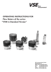
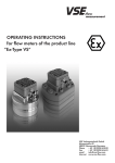
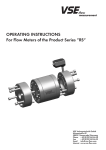
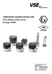
Operating instructions for flow meters of the product line “VS in Standard Version“ VSE Volumentechnik GmbH Hönnestraße 49 58809 Neuenrade/Germany Phone + 49 (0)2394/61630 Fax + 49 (0)2394/61633 E-Mail [email protected] Internet www.vse-flow.com 1 Table of Contents Page Important basic information. . . . . . . . . . . . . . . . . . . . . . . . . . . . . . . . . . . . . . . . . . . . . . . . . . . . . 3 General function description of flow meter. . . . . . . . . . . . . . . . . . . . . . . . . . . . . . . . . . . . . . . . . 4 General description. . . . . . . . . . . . . . . . . . . . . . . . . . . . . . . . . . . . . . . . . . . . . . . . . . . . . . . . . . . 4 Flow meter selection. . . . . . . . . . . . . . . . . . . . . . . . . . . . . . . . . . . . . . . . . . . . . . . . . . . . . . . . . . . 4 Declaration of Conformity. . . . . . . . . . . . . . . . . . . . . . . . . . . . . . . . . . . . . . . . . . . . . . . . . . . . . . 4 General conditions for initial start-up . . . . . . . . . . . . . . . . . . . . . . . . . . . . . . . . . . . . . . . . . . . . . 4 Maximum operating pressure. . . . . . . . . . . . . . . . . . . . . . . . . . . . . . . . . . . . . . . . . . . . . . . . . . . 5 Statement to EU-Directive 97/23/EG, Pressurized devices. . . . . . . . . . . . . . . . . . . . . . . . . . . . . 5 Flow meter range. . . . . . . . . . . . . . . . . . . . . . . . . . . . . . . . . . . . . . . . . . . . . . . . . . . . . . . . . . . . . 6 Assembly of the flow meter . . . . . . . . . . . . . . . . . . . . . . . . . . . . . . . . . . . . . . . . . . . . . . . . . . . . . 6 Cleaning and flushing of pipe lines before initial start-up . . . . . . . . . . . . . . . . . . . . . . . . . . . . . 7 Filtering of liquid. . . . . . . . . . . . . . . . . . . . . . . . . . . . . . . . . . . . . . . . . . . . . . . . . . . . . . . . . . . . . . 7 Preamplifier. . . . . . . . . . . . . . . . . . . . . . . . . . . . . . . . . . . . . . . . . . . . . . . . . . . . . . . . . . . . . . . . . . 7 Maintenance. . . . . . . . . . . . . . . . . . . . . . . . . . . . . . . . . . . . . . . . . . . . . . . . . . . . . . . . . . . . . . . . . 9 Sending back of repairs and sample devices. . . . . . . . . . . . . . . . . . . . . . . . . . . . . . . . . . . . . . . 9 Technical specifications VS 0.02 – VS 4. . . . . . . . . . . . . . . . . . . . . . . . . . . . . . . . . . . . . . . . . . 10 Flow response curves VS 0.02 – VS 4 . . . . . . . . . . . . . . . . . . . . . . . . . . . . . . . . . . . . . . . . . . . . 11 Dimensions VS 0.02 – VS 4. . . . . . . . . . . . . . . . . . . . . . . . . . . . . . . . . . . . . . . . . . . . . . . . . . . . 12 Dimensions, subplates AP. 02 - 4. . . . . . . . . . . . . . . . . . . . . . . . . . . . . . . . . . . . . . . . . . . . . . . . . 13 Technical specifications VS 10. . . . . . . . . . . . . . . . . . . . . . . . . . . . . . . . . . . . . . . . . . . . . . . . . . 14 Flow response curves VS 10 . . . . . . . . . . . . . . . . . . . . . . . . . . . . . . . . . . . . . . . . . . . . . . . . . . . . 14 Dimensions VS 10. . . . . . . . . . . . . . . . . . . . . . . . . . . . . . . . . . . . . . . . . . . . . . . . . . . . . . . . . . . . . 15 Dimensions, subplate APG 10. . . . . . . . . . . . . . . . . . . . . . . . . . . . . . . . . . . . . . . . . . . . . . . . . . . 15 Type key. . . . . . . . . . . . . . . . . . . . . . . . . . . . . . . . . . . . . . . . . . . . . . . . . . . . . . . . . . . . . . . . . . . . 16 Preamplifier–block wiring diagram. . . . . . . . . . . . . . . . . . . . . . . . . . . . . . . . . . . . . . . . . . . . . . . 17 Output signals on preamplifier . . . . . . . . . . . . . . . . . . . . . . . . . . . . . . . . . . . . . . . . . . . . . . . . . . 17 Plug assignment . . . . . . . . . . . . . . . . . . . . . . . . . . . . . . . . . . . . . . . . . . . . . . . . . . . . . . . . . . . . . . 18 Connection diagram . . . . . . . . . . . . . . . . . . . . . . . . . . . . . . . . . . . . . . . . . . . . . . . . . . . . . . . . . . 18 Pick-up system for high temperatures HT. . . . . . . . . . . . . . . . . . . . . . . . . . . . . . . . . . . . . . . . . . . 18 EC-Declaration of Conformity . . . . . . . . . . . . . . . . . . . . . . . . . . . . . . . . . . . . . . . . . . . . . . . . . . 21 2 Important basic information Dear customer, dear user, These installation and operating instructions should provide you with the information you need to properly install and commission the flow meter. Installation, commissioning and testing are to be performed by trained and qualified personnel only. These operating instructions must be read and applied carefully to ensure proper, trouble-free and safe operation of the flow meter. VSE is not liable for any damage incurred resulting from not complying with the instructions in this operating instruction. It is not permitted in any case to open the device. These operating instructions for flow meters of the series ”VS in Standard-Version” from VSE must be stored, so that they can be read by the group of authorized personnel at any time. Chapters may not be taken of these instructions at any time. A missing operating instructions manual or missing pages must be replaced immediately. VSE can supply you with new instructions or you can download the operating instructions from the internet (www.vse-flow.com). The operating instructions must be given to each subsequent user of this product. Legal information This document is not managed by an updating service of VSE Volumentechnik GmbH. Changes to this document may be made without notice. VSE Volumentechnik GmbH does not provide any implicit guarantees of commercial qualities and suitability for a specific purpose. If the device has been opened, modified or incorrectly connected to the electrical circuits, the guarantee of VSE Volumentechnik GmbH for safe operation is void. VSE Volumentechnik GmbH is not liable in any way for personal injuries or damage to goods resulting from improper installation or improper operating of the flow meter. Operating manual–no.: E060014 (E) Date 31th May 2006 3 • General function description of flow meter Flow meters made by VSE Volumentechnik GmbH measure the volume flow of liquids according to the toothed wheel principle. A pair of very precisely adjusted toothed wheels in the housing constitutes the meter. A signal pickup system registers meter rotation free of contact and tooth by tooth. Each tooth is put out as digital pulse. The gaps in the teeth of the meter wheels form meter chambers in the areas, in which they are completely enclosed by the housing walls; these chambers digitalise liquid flow depending on their chamber volume. The liquid flow quantity within one meter rotation of a tooth division forms the volume measurement per pulse (Vm) and is defined in cm3/pulse. It identifies the constructional size of a flow meter. • General description Please follow all instructions in this operating manual; only this guarantees a trouble-free operation of the flow meters. VSE is not liable for any damage ensuing from non-following of these instructions. Opening the devices during the term of guarantee is only authorised after consultation and approval of VSE. • Flow meter selection The correct selection (version) of type and constructional size is crucial for a trouble-free and safe operation of the flow meters. Owing to the great number of various applications and flow meter versions, the technical specifications in the VSE catalogue material are of a general nature. Performance of the flow meter depends on type, size and meter range and on the liquid that is to be measured. Please consult VSE for an exact description. • Declaration of Conformity Flow meters of the “VS” product line are tested for their electromagnetic compatibility and interference transmission in terms of the law on electromagnetic compatibility and correspond to the legal prescriptions enforced by EMC directives. They may not be operated independently and are to be connected via cable to a power source and supply digital electric signals for electronic evaluation. A declaration of conformity is submitted for all flow meters, which you can request if you require. Since the electromagnetic compatibility of the total measuring system depends as well on cable layout, correct connection of protective shielding and each single connected device, you must ensure that all components correspond to the electromagnetic compatibility directives and that the electromagnetic compatibility of the total system, machine or plant is guaranteed. All flow meters are tested according to the valid, legally prescribed electromagnetic compatibility directives EN 55011 and EN 61000 and possess the CE-certification. The EC-declaration of conformity is the CE-label attached to all flow meters. • General conditions for initial start-up Before assembly and before initial start-up, you have to note the following properties and aspects of the corresponding characteristics of your system, so that a trouble-free and safe operation is possible. 1. The process fluid Is the flow meter suitable for the fluid? Is the fluid viscous or abrasive? Is the fluid contaminated or is there solid matter in the fluid? Which granular size does the solid matter possess and can it block the meter? Does the fluid have fillers or other additional material? Is it necessary to install a pre-switched hydraulic filter? Are the pipe lines clean and free of assembly residues such as swarf, weld chips? Is the tank clean and is it ensured that no extraneous materials can get into the pipe line system from the tank? Is the fluid often changed and is sufficient flushing performed in this case? Are the pipe lines and the entire system completely deaerated? What cleaning agent is being used? Are the fluid and the cleaning agent compatible with the seals? Are the seals suitable for the fluid undergoing measurement (seal compatibility)? 4 2. The hydraulic properties of the system Is the max. operating pressure of the system lower than the max. permitted operating pressure of the flow meter? Is the max. fall of pressure ∆p (on flow meter) below the max. permitted fall of pressure? Does an excessively great fall in pressure ∆p occur on the flow meter at max. flow (e.g. with higher viscosity)? Does the flow range of the flow meter (depending on viscosity) correspond to the provided flow? Note that flow range decreases the greater the viscosity! Does the temperature range of the flow meter correspond to the provided max. temperature of the medium? Is the cross section of the pipe line large enough and are the falls in pressure in the system not excessive? Is the hydraulic connection (supply and reverse flow) correctly connected and leak-proof? Has the pump sufficient power to operate the system? A blocking flow meter can stop the whole flow. Is a pressure control valve / bypass provided in the system? 3. Electronic evaluation and electrical safety Have you selected the optimal flow meter and is this equipped with the appropriate preamplifier? Does the power supply voltage of the flow meter correspond to the provided voltage? Is the power supply voltage supplied by the mains or evaluation device sufficiently steady? Does the output of the power supply voltage correspond to the required power output? Has the electric connection been installed based on the enclosed connection plan? Is the cable protective shielding correctly connected on both sides on the earth conductor PE? Is there a potential difference between the earth conductor connection PE on the flow meter and the earth conductor PE on the evaluation device? Does a correcting lead have to be laid to eliminate the potential difference between the flow meter and the evaluation device? Is the flow meter connected firmly to the earth conductor PE (e.g. via the pipe lines)? Is the meter of the flow meter constructed to be insulated to the earth conductor PE (e.g. connection via hoses)? If this is the case, the meter has to be connected with the earth conductor PE! Is there a continuous connection of the cable protective shielding (earth conductor PE) via the housing, of the 4-pin round plug to the housing of the flow meter? Is the cable laid fault-free and the installation secured from input of interference pulses? Is the 4-pin round plug of the connection cable firmly screwed together with the plug of the flow meter? Are the wires on the evaluation device correctly and properly connected? Does the entire system correspond to the directives of the electromagnetic compatibility laws (EMC)? Have all local valid regulations, applicable directives, guidelines and background conditions of the electromagnetic compatibility laws been maintained and observed? Systems that can lead to personal injury through malfunction or failure are to be equipped with the appropriate safety devices. The functioning of these safety devices is to be checked at regular intervals. • Maximum operating pressure Before assembling the flow meter, you have to test that the max. operating pressure of the system does not exceed the max. permitted operating pressure of the flow meter. Meanwhile, observe the top pressures that can occur, when operating the system. The following operating pressures are permitted depending on flow meter version: Flow meter in grey cast iron version pmax = 315 bar / 4500 psi Flow meter in stainless steel version pmax = 450 bar / 6500 psi Flow meter in special version pmax = up to 700 bar / 10100 psi Important: Please consult VSE for all operating pressures > 450 bar / 6500 psi and for special versions. • Statement to EU-Directive 97/23/EG, Pressurized devices VSE flow meters are pressurized devices according to article 1, paragraph 2.1.4. of above mentioned directive. Therefore they are subject to the regulations to this directive. According to article 3, paragraph 1.4, VSE flow meters have to conform with the technical requirements of the guideline. The fluids to be measured are belonging in most of all cases to the class 2, defined in article 9, paragraph 2.2. VSE flow meters do not reach the limit values as defined in article 3, paragraph 1.1. The technical requirements for VSE flow meters therefore are limited to the parts indicated in article 3, paragraph 3. It means the devices have to be designed and manufactured in conformity with acknowledged engineering, such as practiced in one of the member states. This is herewith confirmed. Beside this, the paragraph declares that these devices must not have a CE-marking according to Directive 97/23/ EG. Therefore we do not issue declarations of CE and our products are not labelled acc. to 97/23/EG. 5 • Flow meter range The flow meter range specified in the flow meter data sheet (Qmin - Qmax) refers to the testing fluid “hydraulic oil“ with a viscosity of 21 mm2/s at a temperature of 20°C. For this flow meter range, VSE specifies measurement accuracy of up to 0.3% of the measurement value and a repetition accuracy of 0.05%. For fluids of lower viscosity (< 21 mm2/s) measurement accuracy deteriorates, while for fluids of higher viscosity (> 21 mm2/s) it can improve. Also note, however, that the flow meter range is restricted in case of higher viscosity (see flow meter data sheet). Important: Make sure that the specified maximum permitted operating pressure of the flow meter cannot be exceeded, whatever the operating mode of the system. Note the flow meter range that is dependent on the viscosity of the fluid to be measured. • Assembly of the flow meter The flow meter should be mounted on an easily accessible location, so that dismantling for cleaning the meter presents no problem. Since flow meters can work in any installation position and flow direction, you can mount it on any location of your system that you wish. Take care when installing the flow meter that always liquid remains in the flow meter even at system standstill and that it can never run empty. The outflow of the flow meter should therefore always show a certain back pressure. In critical cases or when the pipe line is at standstill or standby and can run empty, we recommend installing an extra non-return valve in the outflow line. Non-return valve Flow meter Fig. 1: Flow meter installation with non-return valve Tank Important: Make sure that the flow meter is always completely filled both in inflow and outflow and that the outflow has a little back pressure. This prevents the meter being damaged by a sudden and steep increase of flow and at the same time improves measurement accuracy. Flow meters of the “VS” product line can be mounted directly onto a block or into the pipe line using four screws. Always select large cross sections for the hydraulic supply and return flow respectively for the entire pipe line system (if possible). This lowers the fall in pressure and the flow rate in the total system. Block assembly: The flow meter is directly mounted onto a subplate or manifold, extra components are not needed. The block contains the hydraulic supply and outflow of the flow meter and the fixing bore holes (see flow meter dimension sheet). VSE supplies subplates for all flow meters of the “VS” product line; they have various pipe threads and side or rearside connection (see subplates data sheet). Depending on the provided conditions, the installed pipe line, the pipe cross section or pipe thread, the operator can choose the suitable subplate and incorporate this into the system or machine without additional reductions. Table 1: Torque of fastening screws The flow meter is screwed onto the block or subplate with four DIN 912 cheese head screws. The screws are to be evenly pre-tensed crosswise with the following torques. When changing the fastening screws you must take great care that the screws are of property class 10.9 and 12.9. 6 Flow meter, size (cast iron and 1.4305) Torque VS 0.02; VS 0.04; VS 0.1; VS 0.2 15 Nm VS 0.4; VS 1; VS 2 35 Nm VS 4 120 Nm VS 10 250 Nm Please note the special instructions for mounting sizes VS 4 and VS 10 (see appendix) Important: When mounting the flow meter, you must take great care that the seals are not damaged and correctly placed in the hydraulic connections of the flow meter. Wrongly installed or damaged seals lead to leakage and to an leaky system, which may have dire consequences. Please make sure that flow meters with EPDM seals do not come into contact with oil and greases on a mineral oil basis. These fluids can decompose the seals. The yellow plastic plugs in the hydraulic connections of the flow meter protect the meter against dirt and contamination during storage and shipping. Before mounting the flow meter you have to remove these plugs so that in- and outflow is free and open. • Cleaning and flushing of pipe lines before initial start-up Before initial start-up of the flow meter, you must flush and clean the whole system. Contaminated fluids can affect the correct function of the flow meter or seriously damage the meter. After preparing and connecting up the system pipes, you must first carefully flush and clean the whole pipe line system and the tank. To do this, you have to mount a diversion plate onto the block or subplate instead of the flow meter, so that the fluid can flow through the diversion plate and all extraneous material (e.g. swarf, metal chips, etc.) can be flushed out without obstruction. Use a fluid as cleansing agent, which is compatible with the fluid being used later and which does not cause undesirable reactions. You can consult the suppliers and manufacturers of the fluid or contact VSE for the corresponding information. VSE supplies bypass-plates the corresponding for all VS flow meter sizes. Flow meters are measurement pick-up systems made with high-level precision. They have a mechanical meter consisting of two toothed wheels and which is adapted to the housing with narrow slots. Even the tiniest damage to the toothed wheels and bearings can cause a measurement error. So always make sure that no extraneous material gets into the meter and that the fluid flowing through is always free from dirt and contamination. After the system has been carefully flushed out and no extraneous material is in the pipe line, you can mount the flow meter and commence the initial start-up. Important: Please flush out the pipe lines and the tank thoroughly, to prevent contamination with the flow meter. • Filtering of liquid Strongly contaminated fluid or extraneous material in the fluid can block, damage or even destroy the flow meter. Always install a sufficiently large filter for these cases in front of the flow meter to prevent damage. The necessary filtering depends on size, bearing system and version of flow meter. Table 2: Pre-switched filters Flow meter size Filter size for ball bearings VS 0.02 / 0.04 / 0.1 10 µm VS 0.2 / 0.4 20 µm VS 1 / 2 / 4 / 10 50 µm For information on filter size for flow meters with plain bearings, in special version, or with specially adjusted meter tolerances, please consult VSE GmbH. Important: A blocking flow meter can stop the whole flow. You have to provide a control valve / bypass for the system. • Preamplifier The preamplifier for the standard version is short-circuit-proof, reverse- polarity-proof and processes the signals of the scan sensors. A high level of interference protection is achieved through the push-pull output stages of the preamplifier. You can easily connect evaluation devices with both PNP and NPN inputs to the outputs. The two-channel output of digital signals enables a higher measurement resolution and also a direction recognition of the flow. 7 Q 1st Flow direction t 2nd Flow direction Decreasing flow = lowering of sensor frequency 1st flow direction (from A B) 1 3 Increasing flow = raising of sensor frequency 2nd flow direction (from B A) 1* -1 -3 Signal from channel 1 -1* t 2 4 -2 2* -4 -2* Signal from channel 2 t one volume measurement 1 Vm one chamber volume one tooth + one tooth gap one movement of tooth = 360° Change in the direction of flow Q = 0 ml/min Fig. 2: Signal output of preamplifier Power supply voltage in voltage range Ub = 10 … 28 V DC. You can operate the preamplifier with any voltage in this voltage range Ub, but make sure that the signal voltage is always adjusted to the power supply voltage and that the output signal has a signal level of Usig = Ub – 1 V. Permitted for the power supply is a steady direct voltage with a maximum residual ripple of ±15%. Important: Please make sure that no extra inductive elements are connected in the power supply of the flow meter, such as contactors, relays, valves etc. These components are potential sources of interference (especially if the inductive elements are not provided with an adequate protective circuit), generate high interference pulses, when switched and can interfere with the functioning of the flow meter, although this complies with the electromagnetic compatibility directives. The no-load current reception of the preamplifier depends on each power supply voltage. Power supply voltage Ub = 12 V DC Power supply voltage Ub = 24 V DC Max. current per channel I 0max12 = 25 mA I 0max24 = 40 mA I Kmax = 20 mA (the current I K is dependent on the input impedance of the evaluation electronics) Total current reception (at 12 V DC) I 0tot. = I 0max12 + (2 x I Kmax ) I 0tot. = 65 mA Pmax = 0.78 W Total current reception (at 24 V DC) I 0tot. = I 0max24 + (2 x I Kmax ) I 0tot. = 80 mA Pmax = 1.92 W 8 The electric connection of the flow meter is performed via the 4-pin round plug located on the preamplifier housing. The connection cable plug is plugged into the plug connection of the flow meter and screwed together. Important: Only use well-shielded cables for the connection cable, with a wire cross section of ≥ 4 x 0.25 mm2 . Please make sure that the housing of the round plug is metallic, that it has a connection for the shielding and that the potential of the earth conductor PE is connected to the cable shielding and the housing of the preamplifier. The shielding of the connection cable is placed on both sides. The earth conductor PE is connected via the shielding from the evaluation electronics to the preamplifier housing and the meter. The cable shielding should always be laid continuously as far as the flow meter and not interrupted in cross connectors or branch sockets. Lay the connection cable as directly as possible from the evaluating device to the flow meter, since interruptions are always a potential source of error. The flow meter must be connected electrically with the earth conductor PE. This is normally secured by the earthed pipe lines. Pin 2 digital signal 1. channel Pin 1 power supply Ub = 10 – 28 V DC metal housing connected with the shielding and the earth conductor PE Pin 3 power supply GND (-Ub = 0 V) Pin 4 digital signal 2. channel Top view of plug Fig. 3: M12 plug connector installed in the preamplifier housing of the flow meter Important: If there are potential differences between the preamplifier housing and the earth conductor PE of the evaluating electronics, you have to lay a correcting earth (see connection diagram). The maximum cable length between flow meter and the evaluation electronics is approx. 120 m. With extensive cable lengths (as of approx. 40 m) you must take care that the connecting cable is laid in an interference-free environment, that the shielding is connected on both sides of the earth conductor PE and that there is no potential difference between the two earth conductor connections. • Maintenance Working life is dependent on operating conditions and thus the specific properties of the devices, limited through wear, corrosion, deposits or age. The operator is responsible for regular control, maintenance and recalibration. Any indication of a malfunction or damage prohibits any further use. On request, we can supply you with a borrowed device for the duration of repair or overhauling. We advise to a yearly control and recalibration. • Sending back of repairs and sample devices It is imperative that you enclose an exact description of the complaint, objection or fault, when returning the device so as to ensure a rapid and economic repair of the flow meters and other components. Furthermore, you must include a security sheet, which informs unambiguously, which fluid was run with the flow meter and how dangerous this fluid is. The maintenance of legal regulations as regards work safety, such as workplace regulations, accident prevention regulations, stipulations on environmental protection, waste disposal and the water management law, obliges industrial corporations to protect their employees and other persons and environment against harmful effects, when handling hazardous materials. If further safety precautions are still necessary despite careful emptying and cleaning of the flow meter, information on this is imperative and must be included with the returned despatch. When returning flow meters to VSE Volumentechnik GmbH, please note that inspection and repair will only be performed if the safety specifications sheet of the utilised medium is enclosed and the flow meters completely cleaned and flushed. This protects our employees and simplifies our work. If this is not followed, the despatch will be returned, chargeable to the recipient. 9 • Technical specifications VS 0.02 – VS 4 Size Measuring range l/min Frequency Hz Pulse value cm3/pulse K-factor pulse/litre VS 0.02 0.002 … 2 1.667 … 1666.67 0.02 50 000 VS 0.04 0.004 … 4 1.667 … 1666.67 0.04 25 000 VS 0.1 0.01 … 10 1.667 … 1666.67 0.1 10 000 VS 0.2 0.02 … 18 1.667 … 1500.00 0.2 5 000 VS 0.4 0.03 … 40 1.250 … 1666.67 0.4 2 500 VS 1 0.05 … 80 0.833 … 1333.33 1 1 000 VS 2 0.1 … 120 0.833 … 1000.00 2 500 VS 4 1.0 … 250 4,167 … 1041.67 4 250 Measurement accuracy : up to 0.3% of measurement value (with viscosity > 20 mm2/s) Repetition accuracy : ± 0.05% under the same operating conditions Material : Cast iron EN-GJS-400-15 (EN 1563) or Stainless steel 1.4305 Meter bearing : Ball bearings or steel plain bearings (medium-dependent) Seals : FPM (standard), NBR, PTFE or EPDM Max. operating pressure : Cast iron EN-GJS-400-15 (EN 1563) 315 bar / 4500 psi Stainless steel 1.4305 450 bar / 6500 psi Medium temperature : –40 … + 120°C (–40°F … 248°F) Ambient temperature : –20 … + 50°C (–4°F … 122°F) Viscosity range : 1 … 100 000 mm2/s Installation position : any Flow direction : any Running noise : max. 72 db(A) Power supply version : 10 to 28 volts/DC Pulse output : 2 x push-pull output stages reverse-polarity-proof, short-circuit-proof low signal: 0 = GND; high signal: 1 = Ub -1 Imax = 80 mA (at 24 V) Pmax = 1.92 W (at 24 V) Channel offset : 90° ± 30° max. Pulse-width repetition rate : 1/1 ± 15° max. Preamplifier housing : Aluminium Protection type : IP 65 10 Flow resistance ∆p Flow Flowresistance ∆p resistance ∆p Flow resistance ∆p Flow resistance ∆p Flow resistance ∆p Flow resistance ∆p Flow resistance ∆p Flow resistance ∆p • Flow response curves VS 0.02 – VS 4 . VS 0.02 . VS 0.04 Flow Q VS 0.1 . VS 0.4 . VS 2 Flow Q Flow Q VS 0.2. Flow Q Flow Q VS 1 Flow Q Flow Q VS 4 Flow Q 11 • Dimensions VS 0.02 – VS 4 Cast iron version Stainless steel version Connection diagram View X Housing without milled edge Plug position for . . VS 0.02 to VS 0.4 and VS 4 Centring bore hole M12 x 1 Earth Cast iron version Connection diagram View X O-ring M12 x 1 Centring bore hole Plug position for VS 1/VS 2 size A B C D E øG H K L M N O-ring Weight GCI SS kg kg 0.02 100 80 91 M6 12.0 9 114 58 70 40 20 11 x 2 2.8 3.4 0.04 100 80 92 M6 11.5 9 115 59 70 40 20 11 x 2 2.8 3.4 VS 0.1 100 80 94 M6 9 9 117 61 70 40 20 11 x 2 2.8 3.4 0.2 100 80 94 M6 9.5 9 117 61 70 40 20 11 x 2 3.0 3.7 0.4 115 90 96.5 M8 11.5 16 120 63.5 80 38 34 17.96 x 2.62 4.0 5.0 1 130 100 101 M8 12.5 16 124 68 84 72 34 17.96 x 2.62 5.3 6.8 2 130 100 118 M8 15 16 141 85 84 72 34 17.96 x 2.62 6.7 8.4 4 180 140 145 M12 20 30 168 110 46 95 45 36.17 x 2.62 14.7 18.4 Dimensions in mm 12 • Dimensions, subplates AP. 02 - 4 Connection position, side Flow meter Subplate Size VS 0.02 0.04 0.1 0.2 0.4 1 2 4 Connection thread G F A B C D 20 G 1/4“ G 3/8“ øH 35 G 1/2“ 23 G 1/2“ 35 28 40 33 G 1/2“ 35 28 G 3/4“ 40 33 G 1“ 55 41 51 G 1 1/4“ 70 *G 1 1/2“ 70 G 1 1/2“ 80 56 L Thread / depth Weight M kg 100 M6 /12 1.8 115 M8 /15 2.7 130 M8 /15 3.6 26 80 90 40 70 28 G 3/4“ E 30 38 90 100 38 80 100 110 72 84 46 52 46 52 55 120 140 110 130 100 120 110 60 72 M8 /15 180 7.4 12.0 only for AP. 4 U... Connection position below Flow meter Subplate 13 • Technical specifications VS 10 Size Measuring range l/min Frequency Hz Pulse value cm3/pulse K-factor pulse/litre VS 10 1.5 … 525 7.50 … 2625.00 3.333 300 Measurement accuracy : up to 0.5% of measurement value (with viscosity > 20 mm2/s) Repetition accuracy : ± 0.05% under the same operating conditions Material : Cast iron EN-GJS-600-3 (EN 1563) Meter bearing : Ball bearings or steel plain bearings (medium-dependent) Weight : 70 kg without subplate Seals : FPM (standard), NBR, PTFE or EPDM Max. operating pressure : 420 bar / 6000 psi Medium temperature : -40 … 120°C (-40°F … 248°F) Ambient temperature : -20 … + 50°C (-4°F … 122°F) Viscosity range : 5 … 100 000 mm2/s Installation position : any Flow direction : any Running noise : db(A) Power supply version : 10 to 28 volts/DC Frequency range : 0 … 2625 Hz Pulse output : 2 x push-pull output stages reverse-polarity-proof, short-circuit-proof low signal: 0 = GND; high signal: 1 = Ub -1 Imax = 80 mA (at 24 V) Pmax = 1.92 W (at 24 V) Channel offset : 90° ± 30° max. Pulse-width repetition rate : 1/1 ± 15° max. Preamplifier housing : Aluminium Protection type : IP 65 FlowFlow resistance ∆p resistance • Flow response curves VS 10 Flow Q 14 • Dimensions VS 10 View X Connection diagram O-ring Bar handle Lifting eye bolt Weight 70 kg Lifting eye bolt Dimensions in mm • Dimensions, subplate APG 10. APG 10 SG0N / 1 View X Connection surface VS 10 Weight 21 kg APG 10 SW0N / 1 View X Connection surface VS 10 Weight 30 kg Dimensions in mm 15 • Type key Flow meters VS Subplates AP ... 16 Example: Example: • Preamplifier-block wiring diagram Sensor 1 + Volts brown Channel 1 Evalution unit white 0 Volts blue Channel 2 black Sensor 2 signal transformation amplification push-pull output stages Equipotential bonding • Output signals on preamplifier Flow meter VS 0.02 … VS 4 Flow meter VS 10 Meter rotation by one measuring wheel division Gear rotation of one gear tooth pitch 1 puls per throughput amount of liquid by one division 3 impulse pro volume (10 cm3) of one tooth pitch Volume measurement cm 3 /pulse Volume measurement cm 3 /Imp Channel 1 Upp Upp Channel 1 Channel offset by 1/4 division (90°) Channel offset by 1/4 of tooth pitch (90°) Channel 2 Channel 2 Impulse mark/space ratio (adjust. at preamplifier) Pulse-width repetition rate of one pulse (adjusted to preamplifier) Flow direction 1 Flow direction 2 Flow direction 1 Flow direction 2 Voltage ranges Power supply voltage: Signal voltage: UV = 10 … 28 V DC Uss = UV – 1 V 17 • Plug assignment • Connection diagram Modification of flow direction indicator (+ after - / - after +) by interchanging channels (channel 1 _ channel 2) • Pick-up system for high temperatures HT For medium temperatures >120°C, the high temperature (HT) versions by VSE have to be deployed. Flow meters of stainless steel are used exclusively in this case. The sensor or pick-up system consists of a sensor unit, which is screwed into the cover of the flow meter and a downstream amplifier. The amplifier is connected with the flow meter via a temperature-stable cable and has to be installed outside the high temperature zone. The ambient temperature should be no more than 50°C in this area. The digital signals are emitted as PNP- or NPN-signals, depending on amplifier version. With extensive cable lengths, we recommend using shielded cables and a pull-down (PNP signal) or pull-up impedance (NPN signal). Plug assignment HT Pin 1 power supply +U= 10 – 30 V DC Pin 2 digital signal Pin 3 power supply 0V Pin 4 free Top view of plug 18 Connection diagrams HT 1 1 +U +U RL 2 2 Ω 442R 442RΩ 3 RL 3 0V Pulse output NPN-version 0V Pulse output PNP-version Technical specifications HT Sensor Unit Amplifier pick-up system for high temperature range HTS 1 Medium temperature -40°C ... 210°C Supply voltage Ub = 10 … 30 V DC+/- 10% Number of pick-ups 1 or 2 pick ups Current consumption Ib = ca. 18 mA (idle motion, without lead) Pick-up magnetoresistive Signal output PNP High Sign.: US = Ub -1 V; IS = 25 mA max Electrical connection cable gland Signal output NPN Low Sign.: US = 0 V; IS = 25 mA max Seals FPM or EPDM Electrical connection 4 pin round plug M12 Max. ambient temperature -20°C ... 50°C Protection – class IP 64 Pull–Down resistor Rc 4.7 … 10 KΩ PNP-Version Pull–Up resistor Rc 4.7 … 10 KΩ NPN-Version Dimensions flow meter HT O-ring size A D E øG K L M N P O-ring Weight VS 0.04* 100 M6 11.5 ø9 59 70 40 20 22 11 x 2 3.3 VS 0.1 100 M6 9 ø9 61 70 40 20 22 11 x 2 3.3 VS 0.2 100 M6 9.5 ø9 61 70 40 20 22 11 x 2 3.6 VS 0.4 115 M8 11.5 ø 16 63.5 80 38 34 22 18 x 2.62 4.9 VS 1 130 M8 12.5 ø 16 68 84 72 34 22 18 x 2.62 6.7 VS 2 130 M8 15 ø 16 85 84 72 34 22 18 x 2.62 8.3 VS 4 180 M12 20 ø 30 110 46 95 45 12 36.17 x 2.62 18.3 *only available as single-channel version 19 Accessories HT Distribution cable for connection of two HT-pick-ups on a VSE-connecting cable. Connection diagram 2-channel HT-pick-up system Volts Volts Volts Channel 1 Volts Volts Volts 20 Channel 1 EG-Konformitätserklärung EC-Declaration of Conformity CE-Déclaration de Conformité Wir, We, Nous, VSE Volumentechnik GmbH, Hönnestraße 49, 58809 Neuenrade/Germany erklären in alleiniger Verantwortung, dass die Produkte „Volumensensor“ mit der Typenbezeichnung: hereby declare in our sole responsibility, that the product “volumetric sensor“ with the type codes: déclarons de notre responsabilité, que le produit capteur volumétric type: VS *** ******-32N1*/* VSI ***/* ******-32W1*/* Anstelle der Sterne sind Buchstaben und Ziffern eingesetzt, die den Volumensensor kennzeichnen, welche aber keinen Einfluss auf die EMV haben. Instead of stars there are insert letters and numbers, which marked the flow meter but have no influence on the EMC. Des lettres et des chiffres, symbolisant le capteur volumétrique, sont à mettre en lieu et place des astérisques. Ils n`ont aucune influence sur l`EMV. auf die sich diese Erklärung bezieht, mit den folgenden Normen oder normativen Dokumenten übereinstimmt. which is the subject of this declaration, is in conformity with the following standard or normative documents. auquel cette declaration se rapporte, est conforme aux norme ou aux documents normatifs suivants. Bestimmungen der Richtlinien Terms of the directive Prescription de la directive Norm Standard Norme 89/336 EWG: Elektromagnetische Verträglichkeit 89/336 EEC: Electromagnetic compatibility 89/336 CEE: Compatibilité électromagnétique EN 61000-6-4:2001 EN 61000-6-2:2001 Qualitätsmanagementsystem: Quality management: Direction de Qualité: DIN EN ISO 9001:2000-12 QA-Nr.: 04 100 19960054 Neuenrade, den 07.07.2006 Ort und Datum der Ausstellung Place and date of issue Lieu et date d’établissment Axel Vedder Technischer Leiter Technical Director Directeur Technique 21 Notes 22 Notes 23 24 04/09 www.plakart.de VSE Volumentechnik GmbH Hönnestraße 49 58809 Neuenrade/Germany Phone + 49 (0)23 94 /616 30 Fax + 49 (0)23 94 /616 33 E-Mail [email protected] Internet www.vse-flow.com