1
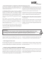
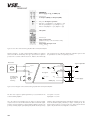
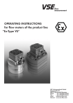
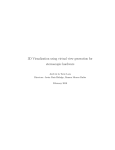
OPERATINGINSTRUCTIONS forflowmetersoftheproductline “Ex-TypeVS“ VSEVolumentechnikGmbH Hönnestraße49 58809Neuenrade/Germany Phone +49(0)2394/61630 Fax +49(0)2394/61633 E-Mail [email protected] Internet www.vse-flow.com 1 Table of Contents Page Important basic information. . . . . . . . . . . . . . . . . . . . . . . . . . . . . . . . . . . . . . . . . . . . . . . . . . . . . . 3 Functional description of the flow meter in areas subject to explosion hazards. . . . . . . . . . . . . 4 Flow Meter Selection. . . . . . . . . . . . . . . . . . . . . . . . . . . . . . . . . . . . . . . . . . . . . . . . . . . . . . . . . . . 4 Declaration of Conformity. . . . . . . . . . . . . . . . . . . . . . . . . . . . . . . . . . . . . . . . . . . . . . . . . . . . . . . 4 General requirements for operation . . . . . . . . . . . . . . . . . . . . . . . . . . . . . . . . . . . . . . . . . . . . . . . 4 Maximum operating pressure . . . . . . . . . . . . . . . . . . . . . . . . . . . . . . . . . . . . . . . . . . . . . . . . . . . . 5 Statement to EU-Directive 97/23/EG, Pressurized devices. . . . . . . . . . . . . . . . . . . . . . . . . . . . . 5 Flow rate range . . . . . . . . . . . . . . . . . . . . . . . . . . . . . . . . . . . . . . . . . . . . . . . . . . . . . . . . . . . . . . . 6 Installing the flow meter. . . . . . . . . . . . . . . . . . . . . . . . . . . . . . . . . . . . . . . . . . . . . . . . . . . . . . . . . 6 Cleaning and rinsing the pipes before operation. . . . . . . . . . . . . . . . . . . . . . . . . . . . . . . . . . . . . 7 Filtering of liquid . . . . . . . . . . . . . . . . . . . . . . . . . . . . . . . . . . . . . . . . . . . . . . . . . . . . . . . . . . . . . . 7 Flow meters in environments subject to an explosion hazard . . . . . . . . . . . . . . . . . . . . . . . . . . . 8 General information on using devices with intrinsically safe circuits. . . . . . . . . . . . . . . . . . . . . . 9 VSE “Ex-Type VS“ flow meters. . . . . . . . . . . . . . . . . . . . . . . . . . . . . . . . . . . . . . . . . . . . . . . . . . . . 9 Isolated switching amplifier MK 13-P-Ex0/24 V DC/K15. . . . . . . . . . . . . . . . . . . . . . . . . . . . . . 9 Technical data for the isolated switching amplifier MK 13-P-Ex0/24 V DC/K15. . . . . . . . . . 11 Control Drawings. . . . . . . . . . . . . . . . . . . . . . . . . . . . . . . . . . . . . . . . . . . . . . . . . . . . . . . . . . . . . 12 FM Approved Isolator Barries. . . . . . . . . . . . . . . . . . . . . . . . . . . . . . . . . . . . . . . . . . . . . . . . . . . 16 Installation of VSE flow meters in explosion hazardous areas. . . . . . . . . . . . . . . . . . . . . . . . . . 17 Safety instructions for installation and operation in explosion hazardous areas. . . . . . . . . . 20 Maintenance and repairs. . . . . . . . . . . . . . . . . . . . . . . . . . . . . . . . . . . . . . . . . . . . . . . . . . . . . . . 21 Maintenance and repair of devices . . . . . . . . . . . . . . . . . . . . . . . . . . . . . . . . . . . . . . . . . . . . . . 21 Technical specifications VS 0.02 – VS 4. . . . . . . . . . . . . . . . . . . . . . . . . . . . . . . . . . . . . . . . . . 22 Flow response curves VS 0.02 – VS 4 . . . . . . . . . . . . . . . . . . . . . . . . . . . . . . . . . . . . . . . . . . . . 23 Dimensions VS 0.02 – VS 4 . . . . . . . . . . . . . . . . . . . . . . . . . . . . . . . . . . . . . . . . . . . . . . . . . . . 24 Dimensions, subplates AP.02 - 4. . . . . . . . . . . . . . . . . . . . . . . . . . . . . . . . . . . . . . . . . . . . . . . . 25 Technical specifications VS 10 . . . . . . . . . . . . . . . . . . . . . . . . . . . . . . . . . . . . . . . . . . . . . . . . . . 26 Flow response curves VS 10 . . . . . . . . . . . . . . . . . . . . . . . . . . . . . . . . . . . . . . . . . . . . . . . . . . . . 26 Dimensions VS 10. . . . . . . . . . . . . . . . . . . . . . . . . . . . . . . . . . . . . . . . . . . . . . . . . . . . . . . . . . . . . 27 Dimensions, subplate APG 10. . . . . . . . . . . . . . . . . . . . . . . . . . . . . . . . . . . . . . . . . . . . . . . . . . . 27 Type key. . . . . . . . . . . . . . . . . . . . . . . . . . . . . . . . . . . . . . . . . . . . . . . . . . . . . . . . . . . . . . . . . . . . 28 Labeling of the flow meters . . . . . . . . . . . . . . . . . . . . . . . . . . . . . . . . . . . . . . . . . . . . . . . . . . . . 29 Safety data for flow meter type VS*** ****** -32Q1 */*. . . . . . . . . . . . . . . . . . . . . . . . . . 29 Maximum ambient and media temperatures . . . . . . . . . . . . . . . . . . . . . . . . . . . . . . . . . . . . . . 30 Preamplifier–block wiring diagram. . . . . . . . . . . . . . . . . . . . . . . . . . . . . . . . . . . . . . . . . . . . . . 30 Summary of the safety-related technical data . . . . . . . . . . . . . . . . . . . . . . . . . . . . . . . . . . . . . . 31 EC-Type Examination Certificate . . . . . . . . . . . . . . . . . . . . . . . . . . . . . . . . . . . . . . . . . . . . . . . . 32 Certificate of Compliance. . . . . . . . . . . . . . . . . . . . . . . . . . . . . . . . . . . . . . . . . . . . . . . . . . . . . . 38 2 Important basic information Dear customer, dear user These installation and operating instructions should provide you with the information you need to properly install and commission the flow meter in potentially explosive hazardous areas according to the regulations. The installation, commissioning, and testing are only to be performed by trained and qualified personnel with knowledge of the relevant national regulations relating to explosion protection. These operating instructions must be read and followed carefully to ensure proper, trouble-free, and safe operation of the flow meter. VSE is not liable for any damage incurred resulting from not complying with the instructions in this operating instruction. It is not permitted in any case to open the device. These operating instructions for flow meters in the series “Ex-Type VS“ from VSE must be stored so that they can be read at any time by the group of authorized personnel. Chapters may not be taken out of these instructions at any time. A missing operating instructions manual or missing pages in operating instructions must be replaced immediately. VSE can supply you with new operating instructions or you can download the operating instructions from the Internet (www.vse-flow.com). The operating instructions must be given to each subsequent user of this product. Legal Information This document is not managed by an updating service of VSE Volumentechnik GmbH. Changes to this document may be made without notice. VSE Volumentechnik GmbH does not provide any implicit guarantees of commercial qualities and suitability for a specific purpose. If the device has been opened, modified or incorrectly connected to the electrical circuits, the explosion protection warranty is void, and therefore the guarantee of VSE Volumentechnik GmbH for safe operation in potentially explosive areas is void. VSE Volumentechnik GmbH is not liable in any way for personal injuries or damage to goods resulting from improper installation or improper operation of the flow meter. Operating manual–No. E060034 (E) Date 31st November 2010 3 • Functional description of the flow meter in areas subject to explosion hazards VS positive displacement flow meters are volume rate measuring sensors, based on the meshing gear principle and are designed for use with liquids. Two precisely matched gear wheels are enclosed in a very accurately machined housing. Gear rotation is sensed by a non-contacting signal pick-up system. Each tooth produces one impulse. The space between the gear teeth, when fully enclosed on both sides by the housing, constitutes measuring chambers. Fluid flow causes the gears to rotate and the incoming flow is separated into discrete volumes within these chambers i. e. the volume of liquid passing through the unit will cause rotation of the gears by exactly one tooth pitch. This volume is known as the Volume/Impulse (Vm) and is stated in cc/Imp. It is used to define the size of a flow meter. The Ex-Type flow meters of the production series “VS” are used in explosion hazardous areas. The preamplifier of this “Ex-Type” supplies two modulated digital current signals, which are staggered at 90° to one another. The frequency of these signals is proportional to the current flow. These separate switching currents are digitalized and amplified by two single-channel isolation switching amplifiers. • Flow Meter Selection The right choice (rating) of the type and size of the flow meter is the deciding factor for the trouble-free and safe operation. Due to the wide variety of applications and flow meter versions, the technical data provided in the VSE catalogs are of a general nature. Certain properties of the devices depend on the type, size and measurement range, as well as on the fluid to be measured. Please contact VSE for exact type and size specifications. • Declaration of Conformity “VS“ series flow meters for areas subject to an explosion hazard have been tested for their electromagnetic compatibility and noise emission according to the EMC-regulations and meet the requirements of the applicable, legally required EMC-directives. They cannot be operated independently. They must be connected to a power source via a cable and they output digital signals for electronic processing. There is a declaration of conformity available for all flow meters. It can be obtained upon request. Since the EM-compatibility of the overall measurement system also depends on the cable routing, on proper connection of the shielding and on every device connected to the system. It must be ensured that all components meet the requirements in the EMC- guidelines and that the electromagnetic compatibility of the entire system, machine or plant is guaranteed. All flow meters are tested according to the applicable, legally required EMC-directive EN 61000. “VS“ Ex-Type flow meters are authorized for use in areas subject to a explosion hazard and fulfill the basic health and safety requirements relating to the design and construction of devices and protective systems according to Appendix II of Directive 94/9/EC (ATEX95) and NEC/NFPA70. Due to the fulfillment of the European standards EN 60079-0, EN 60079-11 and EN 60079-26, US-standards FM3600, FM3610 and FM3810. These devices fulfill the legal health and safety requirements and are certified by accredited certification agencies. You will find an EC-Type Examination Certificate on page 32. The label for EC-Conformity is the CE-Symbol, which is placed on all flow meters. The FM-Certificate of compliance is on page 38. • General requirements for operation Before installation or operation, you must check the following properties of your system and take the following aspects of the corresponding conditions in your system into account for trouble-free and safe operation of the system. 1. The medium to be processed Is the flow meter suitable for the medium? Is the medium viscous or abrasive? Is the medium dirty or is there contamination and suspended particles in the medium? What is the size of the particles of the solid material and could they block the meter? Are there any fillers or other additives in the medium? Is it necessary to install a hydraulic filter before the meter? Are the pipe lines clean and free of scraps left over from the installation such as shavings or weld splatter? Is the tank clean and can any foreign material escape from of the tank and into the pipe line system? Is the type of medium changed often and is the system thoroughly rinsed after changing? Has all air been completely bled from the pipes and the overall system? Which types of cleaners are used? Can the seals withstand the cleaning agents and medium? Are the seals suitable for use with the medium to be measured (compatible with the seals)? 4 2. Hydraulic properties of the system Is the maximum operating pressure of the system smaller than the maximum permissible operating pressure of the flow meter? Is the maximum pressure drop ∆p (on the flow meter) below the maximum permissible pressure drop? Is the pressure drop ∆p excessively large on the flow meter, when the maximum flow rate (at high viscosities, for example) is reached? Does the present flow rate within the flow meter correspond to the flow rate range (depending on the viscosity)? Note that the flow rate range is reduced at high viscosities! Is the maximum temperature of the medium within the temperature range of the flow meter? Is the pipe cross-section large enough and are there any large pressure drops in the system? Are the hydraulic connections (supply and return) correctly connected and sealed? Does the pump have enough power to operate the system? A blocked flow meter can stop the flow throughout the system. Is there an overpressure valve/bypass present in the system? 3. Electronic processing and electrical safety Have you selected the best possible flow meter and is it equipped with the proper preamplifier? Does the power supply voltage applied match the voltage required by the flow meter? Is the supply voltage provided by the power supply or signal processor sufficiently filtered? Does the power supply output the required amount of power? Was the electrical connection wired according to the connection diagram provided? Is the cable shielding connected to the ground conductor? Is there an equalizing conductor connecting the flow meter to the signal processor to eliminate any voltage differences between them? Is the flow meter securely connected to the grounded PE conductor? Is the measuring unit of the flow meter isolated from the grounded PE conductor (e.g. connected using a sleeve)? If it is isolated, then the measuring unit must be connected to the grounded PE conductor! Is the cable routed to prevent interference and can any stray pulses be coupled? Is the 4-pin round plug of the connecting cable screwed tightly to the connector on the flow meter? Are the wires on the signal processor connected correctly and properly? Does the overall system conform to the electromagnetic compatibility (EMC) directives as required by law? Are you following all locally applicable regulations, applicable rules, guidelines and basic requirements for EMC? Are the wires on the signal processor and the isolated switching amplifiers connected correctly? Were the legal regulations and guidelines for explosion protection followed during the installation of the flow meters and other components in the system? Systems in which a malfunction or failure can lead to personal injury are to be equipped with suitable safety equipment. The function of this safety equipment is to be checked at regular intervals. • Maximum operating pressure Before installing the flow meter, you must make sure that the maximum operating pressure of the system does not exceed the maximum permissible operating pressure of the flow meter. Also note the peak pressures can arise, when operating the system. The following operating pressures are permitted depending on flow meter Flow meter in grey cast iron version pmax = 315 bar / 4500 psi Flow meter in stainless steel version pmax = 450 bar / 6500 psi Important: Please consult VSE for all operating pressures > 450 bar /6500 psi and for special versions. • Statement to EU-Directive 97/23/EG, Pressurized devices VSE flow meters are pressurized devices according to article 1, paragraph 2.1.4. of above mentioned directive. Therefore they are subject to the regulations to this directive. According to article 3, paragraph 1.4, VSE flow meters have to conform with the technical requirements of the guideline. The fluids to be measured are belonging in most of all cases to the class 2, defined in article 9, paragraph 2.2. VSE flow meter do not reach the limit values as defined in article 3, paragraph 1.1. The technical requirements for VSE flow meters therefore are limited to the parts indicated in article 3, paragraph 3. It means the devices have to be designed and manufactured in conformity with acknowledged engineering, such as practiced in one of the member states. This is herewith confirmed. Beside this the paragraph declares that these devices must not have a CEmarking according to Directive 97/23/EG. Therefore we do not issue declarations of CE and our products are not labelled acc. to 97/23/EG. 5 • Flow meter range The flow meter range specified in the flow meter data sheet (Qmin – Qmax) refers to the testing fluid “hydraulic oil“ with a viscosity of 21 mm2/s at a temperature of 20°C. For this flow meter range, VSE specifies measurement accuracy of up to 0.3% of the measurement value and a repetition accuracy of 0.05%. For fluids of lower viscosity (< 21 mm2/s) measurement accuracy deteriorates, while for fluids of higher viscosity (> 21 mm2/s) it can improve. The higher the viscosity, the higher the flow resistance ∆p. Also note, however, that the flow meter range is restricted in case of higher viscosity (see flow meter data sheet). Important: Make sure that the maximum permissible operating pressure specified for the flow meter cannot be exceeded in any operating mode of the system. Note the flow rate range of the flow meter, which depends on the viscosity of the measured medium. • Installing the flow meter The flow meter should be installed in a location with easy access so that it can be easily removed to clean the gears. Since flow meters can operate in any mounting position and any direction of flow, you can mount them at any location you want in your system. When installing the flow meter you must make sure that there is always some fluid remaining in the flow meter and that it can never run dry, even when the system is not in operation. For this reason, the outlet of the flow meter should always be under a slight pressure since this firmly fixes the measuring unit of the flow meter in the fluid column (the measuring unit is supported in this fashion by the fluid column) and the pipe line cannot drain empty. In critical cases or when the pipe can run dry, when the system is on standby or stopped, it is strongly recommended to install an additional non-return valve in the outlet line. non-return valve flow meter Tank Fig. 1: Flow meter installation with non-return valve Important: Make sure that both the inlet and outlet of the flow meter measuring unit is always completely full and that there is some pressure on the outlet. This prevents the creation of gas bubbles and the destruction of the measuring unit, when the flow rate suddenly increases rapidly, and it improves the measurement accuracy at the same time. Block mounting: The flow meter is mounted on a subplate. The subplate is installed in the pipe and is equipped with all hydraulic connections and mounting holes required for mounting the flow meter. Series “VS“ flow meters can be mounted with screws on a mounting plate installed in the pipe. Whenever possible, you should choose large diameter pipes for the piping system and large diameter lines for the hydraulic supply and return. This reduces the effect of a pressure drop and lowers the flow rate in the overall system. VSE supplies subplates for all flow meters of the “VS” product line; they have various pipe threads and side or rear-side connection (see subplates data sheet). Depending on the provided conditions, the installed pipe line, the pipe cross section or pipe thread, the operator can choose the suitable subplate and incorporate this into the system or machine without additional reductions. Table 1: Torque of fastening screws The flow meter is screwed onto the block or subplate with four DIN 912 cheese head screws. The screws are to be pretensed crosswise evenly with the following torques. 6 Flow meter, size (cast iron and 1.4305) Torque VS 0.02; VS 0.04; VS 0.1; VS 0.2 15 Nm VS 0.4; VS 1; VS 2 35 Nm VS 4 120 Nm VS 10 250 Nm Please note the special instructions for mounting sizes VS 4 and VS 10 (see appendix) Important: When mounting the flow meter, you must make absolutely sure that the seals are not damaged in any way and are seated correctly in the hydraulic connections of the flow meter. Incorrectly installed or damaged seals can result in leakage and a leaky system can have significant consequences in certain cases. The yellow plastic stoppers in the hydraulic connections of the flow meter protect the measuring unit from dirt and contamination, when the flow meter is placed in storage or for transportation purposes. You must remove these stoppers so that the inlet and outlet are unplugged and open before you mount the flow meter. • Cleaning and rinsing the pipes before operation Before you operate the flow meter, you must carefully clean and rinse the entire system so that no foreign particles can get into the measuring unit of the flow meter, when it is being installed. Foreign particles can block the measuring unit and damage it so badly that the flow meter is unable to supply any valid measurement values any more and must be sent in for repair. After completion of the system or installation of the piping, you must carefully clean and rinse the entire piping system and the tank first. The flow meter must be removed from the piping system to do this.You have to mount a diversion plate onto the block or subplate instead of the flow meter, so that the fluid can flow through the diversion plate and all extraneous material can be flushed out without obstruction. Use a rinsing agent that is compatible with the medium to be used later during operation and will not cause any undesired reactions. You can obtain the corresponding information from your supplier, the manufacturer of the medium, or from VSE. VSE supplies bypass-plates, which are corresponding for all “VS“-flow meter sizes. Flow meters are measuring sensors manufactured to high precision. They have a mechanical measuring unit consisting of two gears and that are fit tightly with small gaps between them and the housing. Even the least damage to the gears or bearings will cause a measurement error. For this reason, you must always make sure that no foreign particles can get into the measuring unit and that the medium being measured is always completely free from contamination. Once the system has been thoroughly rinsed and there are no foreign particles in the piping system, you can mount the flow meter and start operations. Important: Please clean the pipes and the tank thoroughly since foreign particles and residue in the pipes can get into the measuring unit and block it or even destroy it. • Filtering of liquid Heavily contaminated fluid or extraneous material in the fluid can block, damage or even destroy the flow meter. In such cases, always install a sufficiently large filter in front of the flow meter to prevent damage to the flow meter. The necessary filtering depends on size, bearing system and model of flow meter. Table 2: Pre-switched filters Flow meter size Filter size for ball bearings VS 0.02 / 0.04 / 0.1 10 µm VS 0.2 / 0.4 20 µm VS 1 / 2 / 4 / 10 50 µm For information on filter size for flow meters with plain bearings, in special version, or with specially adjusted meter tolerances, please consult VSE. Important: A blocked flow meter can stop the whole flow. You have to provide a control valve/ bypass for the system. 7 • Flow meters in environments subject to an explosion hazard The operation of flow meters in areas with a hazard of explosion is subject to very specific legal regulations. For this reason, only flow meters with certified Ex-authorization are permitted to be used in areas subject to an explosion hazard. To protect people from harm and equipment from damage, lawmakers have issued national and international standards containing regulations that must be followed, when using electrical components and systems in explosive atmospheres. In Europe, CENELEC – the European Committee for Electrotechnical Standardization – issues harmonized regulations relating to explosion protection for electrical equipment. In the U.S. the regulations are issued by the ANSI (American National Standard Institute). A hazard of explosion can arise, when handling flammable, meaning oxidizable substances, when these substances are present as gases (e.g. methane, propane), vapors, mist, or dust; their concentration in a mixture with air is within a certain range; and the quantity of the mixture (flammable substance + oxygen) has reached a hazardous level. An explosion would then occur if a suitable source of ignition is present. An explosion often causes very high temperatures and high rates of pressure. They can injure people and damage buildings, or destroy parts of the system, or even ignite other flammable substances. All electrical equipment installed and operated in an explosive atmosphere require approval for the corresponding zones and must be equipped with a special identification plate. Areas subject to an explosion hazard are divided into zones. The basis for classifying the zones is the probable frequency of occurrence and duration of the explosive atmosphere. The division of the areas into zones is done by the company itself, which means the customer, as an operator, is responsible for the division into zones. In Europe the zone definitions can be found in EN 1127-1 in the section on fundamentals and methods for explosion protection. Further information on zoning is provided in EN 60079-10 and the collection of examples in the explosion protection rules (Ex-RL). For U.S. the NEC/NFPA70, NEC500 and NEC505 supplies to the divisions. Technical inspectors from professional societies can also be contacted for help. The customer can also always contract explosion protection experts from an association for technical inspection to define the zones. In any case, you must obtain approval from the board of industrial and trade supervisors. The operation of electrical equipment and systems in hazardous areas is subject to very specific legal regulations. For this reason, only flow meters with the corresponding Ex-certification and Ex-identification plates, in connection with special certified safety equipment, are permitted to be used in any areas subject to an explosion hazard. The Ex-Type flow meters from VSE GmbH are designed to have the “intrinsic safety” type of protection and are operated with isolated switching amplifiers. The amplifiers must guarantee the intrinsic safety of the signal circuit according to specific criteria and parameters and their limit values may not exceed the highest permitted input value of the device. A single channel isolated switching amplifier is required to operate the Ex-version of the flow meters in the “VS“ series. The “intrinsic safety“ (i/IS) type of protection means that the energy in the circuit is so low that no sparks, arcs, or temperatures can be generated that could cause ignition. When installing intrinsically safe circuits, detailed regulations must be observed. Strict requirements are placed on the isolation to prevent the voltage from creeping into the Ex-range due to parasitic voltages. For this reason, intrinsically safe and non-intrinsically safe circuits must always be routed separately. It is not permitted to install both types together when routing, bundling, or harnessing cables. The European standards basically divide equipment into two different explosion groups. Flow meters belong to Group II (Electrical equipment for hazardous areas). 8 Equipment in Group II are divided further into explosion subgroups and temperature classes. IIA, e.g. acetone, ammonia, benzene (pure), methane, propane IIB, e.g. ethylene, city gas (lighting gas), hydrogen sulfide IIC, e.g. carbon disulfide, acetylene, hydrogen The American standards basically determinte in classes and devisions on the properties of the flammable substance and its likelihood that a flammable concentration is present. The flow meters belong to the Class 1, Devision 1. The equipment is also identified for a specific gas or vapor with a grouping and temperature classes. The flow meters are permitted for the Groups: A (e.g. acetylen), B (e.g. hydrogen), C (e.g. ethylen), D (e.g. propane). The most dangerous substances are placed in Group IIC (Atex) or Class 1, Devision 1 (FM). Devices authorized for Group IIC (Atex) or Class 1, Devision 1 (FM) can also be operated with substances from Group IIA and Group IIB (Atex) or Class 1, Devision 2 (FM). The ignition temperature (defined as the temperature at which a mixture self-ignites in a fixed test setup) is directly related to the temperature class. The temperature class specifies the maximum surface temperature of the electrical equipment and must be lower than the ignition temperature of the flammable substance to prevent ignition. The ambient temperatures and media temperatures permitted for the Ex-Type flow meters are classified according to the corresponding temperature classes, and these temperatures absolutely must be observed (see page 30 ”Maximum ambient and media temperatures“). The Ex-versions of the VSE flow meters are listed with European standards in the “ia” (instinsically safe, when two independent errors occure) category and are permitted for use in Group IIC environments. They can be used in Zone 0, 1, and 2 (for gases and vapors), when the permissible media and ambient temperatures are observed and the installation regulations are followed. The FM-approved ambient and media temperature for Ex-Type flow meters are determinted in the corresponding temperature classes and must be strictly maintained. The Ex-Type of the VSE flow meter is evaluated by the American standards of the FM as intrinsically safe “IS“ for operating in Class 1, Devision 1, Groups A,B,C,D and temperature classes T4…T6 (see page 33). The VSE flow meters are not authorized for use in areas subject to a dust explosion hazard! • General information on using devices with intrinsically safe circuits DIN EN 60079-0 and FM3600 contain general regulations for the design, construction and testing of electrical equipment intended for use in explosive, hazardous atmospheres and specifies the contents of the documentation provided with the devices. For appropriate operation in explosive atmospheres, the national rules and regulations must absolutely be observed and followed at all times. The following contains some information, in particular information on the basic directives from the European Parliament, 94/9/EC (ATEX95) and of the U.S. standard NEC/NFPA70. Intrinsically safe electrical equipment can be connected to the intrinsically safe connections on the isolated switching amplifier. All equipment must meet the requirements for operation in the zone specifying the present explosive atmosphere. When equipment is connected electrically, a “Verification of Intrinsic Safety“ must be performed (EN 60079-14; NEC504). Even if an intrinsically safe circuit is connected just once to a non-intrinsically safe circuit, then the piece of equipment is not authorized for use anymore as a device with intrinsically safe circuits. This applies to the isolated switching amplifiers as well as the flow meters. The prescribed distance between the intrinsically safe connections of the isolated switching amplifier and the grounded components and connections of other devices must be maintained. If not specified expressly in the manual for the specific device, the opening of the device for repairs or modifications to the device not performed by qualified experts or the manufacturer will result in the invalidation of the Ex-authorization. Visible changes to the device housing of the isolated switching amplifier (e.g. black or brown discoloration due to heat or any holes and dents) indicate a serious error and the device should be switched off immediately in this case. In addition, the connected flow meter must be inspected. Note that the inspection of the device in terms of its explosion protection properties can only be performed by a qualified expert or the manufacturer. Operation of the isolated switching amplifier is only permitted within the authorized limits printed on the housing. You must make sure that the applicable regulations, guidelines, directives and general conditions for operation are observed every time before operating the device or changing its connections, the conditions for appropriate operation and the safety regulations are met. The relevant, applicable regulations apply to the installation of intrinsically safe circuits, the mounting of external connectors, and the properties and routing of lines and cables. Cables and terminals with intrinsically safe circuits must be labeled accordingly and must be safely isolated from non-intrinsically safe circuits. Important: The installation and connection of the isolated switching amplifier and the flow meter are only to be performed by trained and qualified personnel (authorized personnel) with knowledge of the relevant national regulations relating to explosion protection. For the owner/operator the most important guidelines for the setup, installation, operation, testing and maintenance of the system in a hazardous area are, among others, the guidelines ATEX 95, ATEX 137 and the European standards EN 1127-1, EN 60079-10, EN 60079-14, and EN 60079-17 and the American standards NEC/NFPA70 articles 504, 505 and ANSI/ISA–RP12.06.01. These guidelines must be followed. • VSE ”Ex-Type VS“ flow meters The VSE flow meters in the “Ex-Type VS “ series from VSE are authorized for use in hazardous areas and are always operated together with an isolated switching amplifier. They provide the required explosion protection safety. On the type plate you will find the specifications, labels and safety-related and electrical data required according to DIN EN 60079-0 and FM3600 (see page 29 “Labeling of the flow meters“). VSE supplies the flow meters with isolated switching amplifier models MK 13-P-Ex0/24 V DC/K15. • Isolated switching amplifier MK 13-P-Ex0/24 V DC/K15 The isolated switching amplifier MK 13-P-Ex0/24 V DC/K15 allows binary switching states to be transmitted, while electrically isolated. It has an intrinsically safe circuit and is certified according to II (1) GD [EEx ia] IIC for the EU. For the U.S. it is suitable for CL1; Div 2; GRPS A, B, C, D hazardous locations with IS Entity connections to CL1; Div 1; GRPS A, B, C, D. The input circuit and output circuit are electrically isolated from each other and from the supply voltage. An isolated switching amplifier is required to operate the Ex-version flow meters in the “VS“ series. The input circuit can be monitored for open circuits and short circuits (the monitor can be disabled using a wire jumper). An error in the input circuit will block the signal output, but will not be output as an error message. Two positively switching (PNP-outputs), short circuit-proof transistor outputs, output the antivalent digital signal. 9 Terminals 7, 8 Power supply: 7 = Ub ; 8 = GND (0 V) Terminals 5, 6 5 = Output 1 (PNP); 6 = Output 2 (PNP) LED green = Ready for operation LED yellow = signal (Output 1 = Ub; Output 2 = open) LED off = signal (Output 1 = open; Output 2 = Ub) LED red = fault (Output 1 = open; Output 2 = open) Label plate Terminals 3, 4 Input circuit monitor (disable monitoring = connect terminals 3 and 4) Terminals 1,2 Intrinsically safe input circuit 1 = +Uex; 2 = +Uex Figure 2: View of the isolated switching amplifier MK 13-P-Ex0/24 V DC/K15 The blue terminals 1...4 of the isolated switching amplifier are equipped with circuits with the ”intrinsically safe“ type of protection for explosion protection in accordance with EN 60079-11; FM3600. The intrinsically safe circuits have been certified by authorized certification agencies and are permitted for use in the corresponding countries. Flow meter + 1 pnp +8,2 V Imax = 100 mA signal - Potential bridge for switching off input circuit monitoring YE/RD 2 pnp 500 Ω +Ub inv. signal 4 Imax = 100 mA 6 R 3 Ex Signal output PNP 5 +Ub Pwr = power GN +Ub GND (-Ub) 7 8 R + Power supply - Figure 3: Circuit diagram of the isolated switching amplifier MK 13-P-Ex0/24 V DC/K15 The flow meter outputs a digital signal that is processed further in the isolated switching amplifier. Low Signal = < 2.7 mA High Signal = > 3.7 mA Since the signals are transmitted using an impressed electrical signal, only two wires are needed in the transmission cable to transmit the signal. From the electrical signal, the isolated switching amplifier generates the positively switching output signal (PNP-signal) and the inverted positively switching output signal (PNP-signal). Normally the signal processor only needs the standard signal generated (see figure 3 and figure 4), the inverted signal is only processed in special cases. That is why the inverted signal is only shown in the circuit diagram as a dotted line. 10 One volume measurement = 1 Vm Signal Inverted signal Figure 4: Signal output of the isolated switching amplifier Note: Note that the signal output of the isolated switching amplifier is a PNP-signal (low signal = open output; high signal = Ub). Problems may arise, when the signal processor has high impedance inputs, especially in the higher range of flow rates. The signal edges become rounded, and the signal processor cannot detect the digital signal any more. In this case, insert a pull-down resistor with a resistance of approx. 2.2 – 4.7 kΩ parallel to the input of the signal processor (see figure 3; Resistor R). • Technical data for the isolated switching amplifier MK 13-P-Ex0/24 V DC/K15 Manufacturer Werner Turck GmbH & Co. KG Type designation MK13-P-Ex0/24 V DC/K15 Operating voltage Residual ripple WSS Current consumption Galvanic isolation 10 ... 30 V DC ≤ 10% approx. 20 mA Input circuit to output circuit and supply voltage for 250 Veff Test voltage 2.5k Veff Input circuit Operating values - No-load voltage U0 - No-load current I0 - Internal resistance Ri Switch points Open circuit threshold Short-circuit threshold 8.2 V 16.4 mA ≤ 500 Ω 2.9 ... 3.5 mA (± 0.2 mA) ≤ 0.16 mA ≤ 12.4 mA Output circuit Two transistor outputs, shortcircuit proof, positive switching Voltage drop Switching current per output Switching frequency ≤ 2.5 V ≤ 100 mA ≤ 3 kHz Ex-certified according to Conformity certificate Maximum values - No-load voltage U0 - Short-circuit current I0 - Power P0 PTB 06 ATEX 2025 | FM-ID. 3026923 ≤ 9.9 V ≤ 9.6 V ≤ 22 mA ≤ 19.4 mA ≤ 54 mW ≤ 46.6 mW External inductances/capacitances and inductances L0 /C0 - [EEx ia] IIB - [EEx ia] IIC - Group A/B/IIC - Group C/IIB - Group D/IIA 2/10/20mH / 5/3.5/3 µF (ATEX) 1/5/10mH / 1.1/0.75/0.65 µF (ATEX) 82 mH; 3.6 µF (FM) 296 mH; 26 µF (FM) 700 mH; 210 µF (FM) Temperature range TU -25°C ... +70°C -13°F … +158°F Device label II (1) GD [EEx ia] IIC (ATEX) Associated Equipment Suitable for CL1; Div 2; GRPS A, B, C, D hazardous locations with IS entity connections to CL 1; Div 1; GRPS A, B, C, D (FM) LED indicators - Switching state/error message - Ready for operation yellow/red (two-color LED) green Terminal box Dimensions Connection Connection cross-section Type of protection (IEC 60529 / EN60529) Operating temperature range 8-pin, polycarbonate/ABS Flammability class V-0 according to UL94 can be clipped on the top hat rail (DIN 50022) or clip-on on mounting plate Height: 89 mm, Length: 70 mm, Width: 18 mm Flat terminals with self-lifting pressure plates ≤ 2 x 2.5 mm2 or 2 x 1.5 mm2 with wire end ferrules IP 20 -25°C ... +70°C -13°F … +158°F 11 • Control Drawings Hazardous (Classified) Location Class I; Division 1; Groups A, B, C & D T4 … T6 Unclassified Location Note: T4 Temperature code based on 80°C (176°F) T5 Temperature code based on 70°C (158°F) T6 Temperature code based on 55°C (131°F) Flow Meter System Series VS** ******-32Q1*/* EF*** Q*****-*/* ASSOCIATED APPARATUS WITH ENTITY PARAMETERS Vmax (or Ui) = 18.5 V Voc (or uo) ≤ Vmax (or Ui) Isc (or Io) ≤ Imax (or Ii) = 270 nF Po ≤ Pi Li =0 Ca (or Co) ≤ Ci + Ccable Ri =0 Imax (or Ii) = 24 mA Pi = 100 mW Ci 1 1 2 2 La (or Lo) = Li + Lcable 4 1 Voc (or uo) ≤ Vmax (or Ui) Channel 1 Vmax (or Ui) = 18.5 V Imax (or Ii) = 24 mA Pi = 100 mW Isc (or Io) ≤ Imax (or Ii) Ci = 270 nF Po ≤ Pi Li =0 Ca (or Co) ≤ Ci + Ccable La (or Lo) = Li + Lcable Ri =0 3 2 Channel 2 G Potential Equalisation 1.The installation must be in accordance with the National Electrical Code, NFPA 70, Articles 504 and 505 and ANSI/ISA-RP12.06.01. 2.The flow meter systems series VS** ******-32Q1*/* and EF** Q*****-*/* are suitable for use in Class I, Division 1 and Zone 0 (AEx ia) applications. If connected to associated apparatus the flow meter systems VS** ******-32Q1*/* and EF** Q*****-*/* may be used in areas classified as zones. If connected to AEx [ib] associated appa- ratus, the flow meter system may only be used in Zone 1 or 2 Hazardous (Classified) Locations. 12 3. In order to suppress inductive interference, a connecting cable with the shield bearing on the coupling nut of the four-pole circular plug-in connect or must be used during the installation of the flow meter. In explosion- hazardous areas the flow meter is connected to the ground potential. The greatest care must be taken to ensure that between each end of the elec- trical circuit (i.e. between the explosive area and the non-explosive area) potential equalisation exists. Drawing No. V 06 606 4 Date 15th November 2006 Hazardous (Classified) Location Class I; Division 1; Groups A, B, C & D T4 … T6 Unclassified Location Note: T4 Temperature code based on 80°C (176°F) T5 Temperature code based on 70°C (158°F) T6 Temperature code based on 55°C (131°F) Flow Meter System Series VS** ******-32Q1*/* EF*** Q*****-*/* ASSOCIATED APPARATUS WITH ENTITY PARAMETERS Vmax (or Ui) = 18.5 V Imax (or Ii) = 24 mA P i = 100 mW C i = 270 nF Li =0 Ri =0 1 2 1 2 Voc (or uo) ≤ Vmax (or Ui) Isc (or Io) ≤ Imax (or Ii) Po ≤ Pi Ca (or Co) ≤ Ci + Ccable La (or Lo) = Li + Lcable Channel 1 Vmax (or Ui) = 18.5 V Imax (or Ii) = 24 mA P i = 100 mW C i = 270 nF Li =0 Ri =0 4 3 Channel 2 G Potential Equalisation 1.The installation must be in accordance with the National Electrical Code, NFPA 70, Articles 504 and 505 and ANSI/ISA-RP12.06.01. 2.The flow meter systems series VS** ******-32Q1*/* and EF** Q*****-*/* are suitable for use in Class I, Division 1 and Zone 0 (AEx ia) applications. If connected to associated apparatus the flow meter systems VS** ******-32Q1*/* and EF** Q*****-*/* may be used in areas classified as zones. If connected to AEx [ib] associated appa- ratus, the flow meter system may only be used in zone 1 or 2 Hazardous (Classified) Locations. 3. In order to suppress inductive interference, a connecting cable with the shield bearing on the coupling nut of the four-pole circular plug-in con- nect or must be used during the installation of the flow meter. In explo- sion-hazardous areas the flow meter is connected to the ground potential. The greatest care must be taken to ensure that between each end of the electrical circuit (i.e. between the explosive area and the non-explosive area) potential equalisation exists. Drawing No. V 06 60 74 Date 15th November 2006 13 Hazardous (Classified) Location Class I; Division 1; Groups A, B, C & D T4 … T6 Unclassified Location Note: T4 Temperature code based on 80°C (176°F) T5 Temperature code based on 70°C (158°F) T6 Temperature code based on 55°C (131°F) ASSOCIATED APPARATUS Isolator barrier MK13-P-Ex0/24 V DC/K15 (TURCK) Flow Meter System Series VS** ******-32Q1*/* EF*** Q*****-*/* 1 1 Channel 1 2 2 4 1 2 3 Channel 2 Isolator barrier 5 MK13-P-Ex0/24 V DC/K15 6 Entity Parameters shown in table below 7 Isolator barrier 8 5 MK13-P-Ex0/24 V DC/K15 6 Entity Parameters shown in table below 7 8 G Potential Equalisation Terminals Group Ccable (µF) Lcable (mH) 1–2 A/B/IIC 3.3 82 1–2 C/IIB 25.7 296 1–2 D/IIA 209.7 700 1.The installation must be in accordance with the National Electrical Code, NFPA 70, Articles 504 and 505 and ANSI/ISA-RP12.06.01. Power supply: 24 V DC The isolator barrier shall be installed in a tool secured enclosure in compliance with the mounting, spacing and segregation requirements of the ultimate application. 2.In order to suppress inductive interference, a connecting cable with the shield bearing on the coupling nut of the four-pole circular plug-in connect or must be used during the installation of the flow meter. In ex- plosion-hazardous areas the flow meter is connected to the ground potential. The greatest care must be taken to ensure that between each end of the electrical circuit (i.e. between the explosive area and the non-explo- sive area) potential equalisation exists. Drawing No. V 06 6 12 4a 14 Date 15th November 2006 Hazardous (Classified) Location Class I; Division 1; Groups A, B, C & D T4 … T6 Unclassified Location Note: T4 Temperature code based on 80°C (176°F) T5 Temperature code based on 70°C (158°F) T6 Temperature code based on 55°C (131°F) ASSOCIATED APPARATUS Isolator barrier MK13-P-Ex0/24 V DC/K15 (TURCK) Flow Meter System Series VS** ******-32Q1*/* EF*** Q*****-*/* 1 1 2 Channel 1 2 Isolator barrier 5 MK13-P-Ex0/24 V DC/K15 6 Entity Parameters shown in table below 7 8 4 3 Channel 2 G Potential Equalisation Terminals Group Ccable (µF) Lcable (mH) 1–2 A/B/IIC 3.3 82 1–2 C/IIB 25.7 296 1–2 D/IIA 209.7 700 1.The installation must be in accordance with the National Electrical Code, NFPA 70, Articles 504 and 505 and ANSI/ISA-RP12.06.01. Power supply: 24 V DC The isolator barrier shall be installed in a tool secured enclosure in compliance with the mounting, spacing and segregation requirements of the ultimate application. 2.In order to suppress inductive interference, a connecting cable with the shield bearing on the coupling nut of the four-pole circular plug-in connect or must be used during the installation of the flow meter. In ex- plosion-hazardous areas the flow meter is connected to the ground potential. The greatest care must be taken to ensure that between each end of the electrical circuit (i.e. between the explosive area and the non-explo- sive area) potential equalisation exists. Drawing No. V 06 6 13 4a Date 15th November 2006 15 16 • Installation of VSE flow meters in explosion hazardous areas The following figures show the wiring diagrams for flow meters in the “VS“ series for use in areas subject to an explosion hazard. Connect each piece of equipment as shown in the diagram. Isolated switching amplifiers also contain non-intrinsically-safe circuits and may not be installed in hazardous areas. The non-intrinsically-safe circuits are to be installed according to IEC 60364-4-4*. Flow meters in hazardous areas are to be connected to a grounding system grounded according to the applicable regulations. VSE supplies connection cables for EMC-safe operation in which the shield is seated on the union nut of the four-pin circular connector. It is not necessary for EMC-safe operation, but it is recommended to connect the shield to a ground connection at the other end of the connection cable, i.e. in the non-hazardous area. You must always make sure that the grounded conductor “PE“ is correctly connected with the flow meter and that no voltage differences can arise between the grounded conductor PE connections (flow meter » isolated switching amplifier » electronic signal processor). To accomplish this, always install an extra wire connection (about Ø 4 ... Ø 6 mm2) between each of the pieces of equipment (see the PE arrows in the following figures) or connect every single PE connection point in a star configuration to a specific location on the grounded conductor PE. There is a terminal for this on the measuring unit housing. A conductor with a minimum diameter of 4 mm2 can be connected here. Important: Mounting and installation must always be performed according to the locally applicable regulations and the owner of the measuring unit is responsible for abiding by these regulations. All installations are to be performed to ensure EM-compatibility. You must make sure that no voltage differences can arise between the pieces of equipment and must install potential equalization! The wiring diagram in figure 5 shows the processed signal of one channel from the flow meter. With this measuring system you can measure the flow rate and the volume, but it is not possible to detect the direction of flow, when connected in this manner. Explosion-hazardous atmosphere Flow meter 1 + - 2 brown white Normale atmosphere Isolation switching amplifier 1 2 3 4 5 pnp 6 pnp 7 + power 8 + - - General signal processor signal inv. signal Ub+ GND (0V; Ub-) MK V DC/K15 MK13-P-Ex0/24 13-P-Ex0/24VDC/K15 PE PE PE PE Figure 5: Evaluation of one channel Important: This processing unit can be used, when it is ensured that the flow volume can flow in only one direction. When the flow direction changes (also short term), the receiver does not perceive this return flow, and a measurement error occurs. 17 Explosion-hazardous atmosphere Flow meter Normal atmosphere Isolation switching amplifier: 1. Channel 1 + - 2 + 4 - 3 1. Channel brown 1. Channel white 2. Channel black 2. Channel blue + 2 - MK 13- P-Ex0/24 V DC/K15 PE inv. signal (1. Channel) signal (2. Channel) inv. signal (2. Channel) 6 pnp 7 + 8 - 3 signal (1. Channel) 5 pnp + 2 - PE 7 + power 8 - 1 4 6 pnp 3 4 5 pnp 1 General signal processor power MK 13- P-Ex0/24 V DC/K15 Isolation switching amplifier: 2. Channel PE Ub+ GND (0 V; U b-) PE Figure 6: Evaluation of two channels (standard circuit) As a rule, this circuit is used as the standard. The electronic processing unit processes the digital signals from channels 1 and 2 and supplies the current. The inverted signals of the channels are not required for the evaluation so that they are omitted and you only need a four-strand cable. With the figure 7 circuit, you can create two autarchic functioning signal systems. This type of flow meter has two galvanic isolated circuits, which ope- Explosion-hazardous atmosphere Flow meter 1 + - 2 + 4 - 3 rate separately, thus allowing a separate processing of the signals (channel 1 and channel 2). As you can see in figure 7, the signals are transmitted through isolation switching amplifiers, which operate separately. The two systems are fed by two sources of power. Since the two signal systems are galvanically isolated from one another and operate independently, this type is used in equipment and systems, which operate redundantly. Even if one of the signal systems fails, the other continues to function. Normal atmosphere Isolation switching amplifier: 1. Channel pnp 1 1. Channel brown 1. Channel white 2. Channel black 3 2. Channel blue 4 + 2 - pnp 5 6 7 + power 8 - MK 13- P-Ex0/24 V DC/K15 General signal processor signal (1. Channel) inv. signal (1. Channel) Ub1+ GND1 (0 V; Ub1-) Isolation switching amplifier: 2. Channel pnp 1 + 2 - pnp 3 4 PE PE 6 7 + power 8 - MK 13- P-Ex0/24 V DC/K15 PE 5 signal (2. Channel) inv. signal (2. Channel) Ub 2+ GND2 (0 V; Ub 2-) PE Figure 7: Galvanic isolation between the channels through separate power supply Important: The isolation switching amplifier MK13-P-Ex0/24 V DC/K15 is manufactured by the WERNER TURCK GmbH & Co. KG exclusively for the Ex-Type flow meters of the VSE Volumentechnik GmbH! The connection diagram in figure 6 shows the processing of two channels of the flow meter. With this measuring system, you can measure the flow rate and volume in both directions of flow. 18 Evaluation Unit 1. Channel 2. Channel Power Supply Ub U b Conductor PE =PE PE* Normal atmosphere Brown = +Ub ( 1. Channel ) White = - Ub ( 1. Channel ) Black = +Ub ( 2. Channel ) Blue = - Ub ( 2. Channel ) Shielding Explosion-hazardous atmosphere PE* Fluid Figure 8: Connection of flow meter and isolated switching amplifier Important: Persons assigned or contracted to install, commission and operate the devices must have appropriate qualifications above and beyond those required for their normal tasks. In particular, they must have knowledge of explosion protection. 19 • Safety instructions for installation and operation in hazardous areas • Only qualified personnel, meaning authorized persons with special explosion protection training, are permitted to install explosion- protected equipment and systems! • The qualified personnel must have read and understood the installa- tion regulations and the corresponding type Examination Certificates and Declarations of Conformity! • Work may only be done on the devices in a de-energized state! • Before you operate the flow meter, you must carefully clean and rinse the entire system so that no foreign particles from the installation can get into the measuring unit of the flow meter. • The pipes and the flow meter must always be filled in operation so that no gas bubbles can form! • Extremely dirty media or foreign particles in the medium can block, damage or even destroy the measuring unit. In these cases you should always install a sufficiently rated filter before the flow meter so that no foreign particles or substances can get into the measuring unit and damage the flow meter. • The VSE flow meters are not authorized for use in areas subject to a dust explosion hazard! • To suppress inductive interference, you must use the connection cable in which the shield is seated on the union nut of the four-pin circular connector, when installing the flow meter. In hazardous areas, the flow meter is connected to a ground potential. You must be extremely certain that there is an equalization of potential between each end of the circuit (i.e. between the hazardous and non-hazardous areas). The potential equalization of the ground conductor PE must be present throughout the entire area. • The owner must maintain the system in proper operating condition, operate the system properly, monitor it constantly, perform the necessary maintenance and any related work immediately, and follow the relevant safety regulations, when doing so. This procedure, known as continuous monitoring, will eventually be adopted as a new law in Europe! • • VSE supplies special flow meters from the “VS“ series, when the flow meter is to be operated in a hazardous area. These flow meters are authorized for use in hazardous areas and must always be operated in conjunction with isolated switching amplifiers that guarantee intrinsic safety and are Ex-certified. They are marked in blue and offer the safety level required for explosion protection! The isolated switching amplifiers must guarantee the “ia“ level (DIN EN 60079-11) of intrinsic safety of the signal circuit, and their limit values may not exceed the highest permitted input value of the flow meter. • When equipment is connected electrically, a “Verification of Intrinsic Safety“ must be performed (EN 600079-14; FM 3600). Even if an in- 20 trinsically safe circuit is connected just once to a non-intrinsically safe circuit, then the piece of equipment is not authorized for use anymore as a device with intrinsically safe circuits. This applies to the isolated switching amplifiers as well as the flow meters. The relevant, appli- cable regulations apply to the installation of intrinsically safe circuits, the mounting of external connectors, the properties and routing of lines and cables. Cables and terminals with intrinsically safe circuits must be labeled accordingly and must be isolated from non-intrin- sically safe circuits or be equipped with the appropriate isolation (EN 60079-14; FM 3600)! • The sum of the maximum effective capacitance Ci and inductivity Li of the flow meter and the four-pin connection cable may not exceed the maximum values C0 (Ca) and L0 (La) of the corresponding isolated switching amplifier. Pay attention to the manufacturer‘s specifications for the connection cable and to the lengths of the cables used. • It must be especially observed that the radial thickness of the insulation of a conductor for conventional insulation materials e.g. polyurethane, have a minimum thickness of 0.2 mm. The diameter of a finely stranded conductor must not be smaller than 0.1 mm. The ends of the conductor have to be protected against fanning out, e.g. by ferrules. In addition to this the sheath insulation must be tested in respect of electrostatic charge to ensure a safe use in the intrinsically safe area. The VSE-Ex-cable corresponds to these requirements. • It must be especially observed that for the use of devices with two channels there exist two intrinsically safe power circuits in a cable. Here please observe chapter 12.2.2.7/8 of EN60079-14. An installation firm and protected against damages is always necessary for this kind of operation. • The permissible ambient and media temperatures in the correspon- ding temperature class may not be exceeded at any time, when operating the flow meter. • When operating or performing maintenance or repairs on the flow meter, the surface of the flow meter housing must be safely protected from impact or sharp edges, tools or other items! • The preamplifier housing is made of die cast aluminum. The genera- tion of impacts and friction, especially between aluminum and steel, must be prevented so that the production of sparks is ruled out! • When using the flow meters (Ex-Type VS) in hazardous areas re- quiring category 1 equipment, the sensor is to be installed so that sparks from impact or friction can be ruled out! Furthermore the ope- rator has to judge the suitability of the device for special application. • You may not change or extend the devices in any way, if the modifications were not expressly permitted by the manufacturer. If the preamplifier housing is opened, then the explosion protection certification becomes invalid! • Maintenance and repairs VSE flow meters are basically maintenance-free. However, it is recommended to send the flow meters back to the factory at regular intervals for inspection, particularly in difficult applications, when critical media are used (e.g. when using abrasive, contaminating media or media containing fillers or pigments), when high viscosity media are used, or when very heavy strain is placed on the measuring unit (e.g. when the flow changes often and quickly). In this manner, any minor damage can be detected and eliminated early, before the damage leads to total failure during production, whether the failure is caused by a faulty bearing or a blockage of the gears. The owner is responsible for regular inspections, maintenance and recalibration. The flow meters may not be used in any case, when damage or a fault is detected in the meter. We advise to a yearly control and recalibration. Repairs may only be performed by the manufacturer or by authorized personnel. Any other repairs must be examined by an expert. • Maintenance and repair of devices To ensure fast and economical repair of the flow meters and other components, it is absolutely necessary to include a precise description of the problem or error with the package you send back to VSE. Furthermore, a safety data sheet must also be enclosed in which it is clearly stated, which medium was used with this flow meter and any potential hazards the corresponding medium may attribute. The legal regulations relating to occupational safety, accident prevention regulations, regulations relating to environmental protection, waste disposal and water resources law oblige companies, their employees and other persons, and the environment from harmful effects, when handling hazardous substances. If additional safety precautions are still required in spite of thorough draining and cleaning of the flow meter, then this information absolutely must be enclosed in the package sent back to VSE. Note that examination and repair of any flow meters sent to VSE Volumentechnik GmbH will only be performed, when the safety data sheet of the medium used is enclosed and the flow meters have been completely cleaned and rinsed. This serves to protect our employees and makes our job easier. When these instructions are not followed, the package will be returned at the sender‘s expense! 21 • Technical specifications VS 0.02 – VS 4 Size Measuring range l/min Frequency Hz Pulse value cm3/pulse K-factor pulse/litre VS 0.02 0.002 … 2 1.667 … 1666.67 0.02 50 000 VS 0.04 0.004 … 4 1.667 … 1666.67 0.04 25 000 VS 0.1 0.01 … 10 1.667 … 1666.67 0.1 10 000 VS 0.2 0.02 … 18 1.667 … 1500.00 0.2 5 000 VS 0.4 0.03 … 40 1.250 … 1666.67 0.4 2 500 VS 1 0.05 … 80 0.833 … 1333.33 1 1 000 VS 2 0.1 … 120 0.833 … 1000.00 2 500 VS 4 1.0 … 250 4.167 … 1041.67 4 250 Measurement accuracy : up to 0.3% of measurement value (with viscosity > 20 mm2/s) Repeating accuracy : ± 0.05% under the same operating conditions Materials : Cast iron EN-GJS-400-15 (EN 1563) or stainless steel 1.4305 Gear bearing : Ball bearings or steel plain bearings (medium-dependent) Seals : FPM (standard), NBR, PTFE or EPDM Max. operating pressure : Cast iron EN-GJS-400-15 (EN 1563) 315 bar / 4500 psi stainless steel 1.4305 450 bar / 6500 psi Viscosity range : 1 … 100 000 mm2/s Installation position : unrestricted Direction of flow : unrestricted Running noise : max. 72 db(A) Channel offset : 90° ± 30° max. Pulse-width repetition rate : 1/1 ± 15° max. Preamplifier housing : Aluminum Protection type : IP 65 22 Flow resistance ∆ p Flow resistance ∆ p Flow resistance ∆ p Flow resistance ∆ p Flow resistance ∆ p Flow resistance ∆ p Flow resistance ∆ p Flow resistance ∆ p • Flow response curves VS 0.02 – VS 4 VS 0.02 VS 0.04 Flow Q VS 0.1 VS 0.4 VS 2 Flow Q Flow Q VS 0.2 Flow Q Flow Q VS 1 Flow Q Flow Q VS 4 Flow Q 23 • Dimensions VS 0.02 – VS 4 Stainless steel version Connection diagram Housing without miled edge Cast iron version View X Earth X Plug position for VS 0.02 to VS 0.4 and VS 4 Centering bore hole Earth Cast iron version Connection diagram View X Centering bore hole Plug position for VS 1/VS 2 Size O-ring A B C D E øG H K L M N O-ring weight GCI E kg kg 100 80 91 M6 12.5 9 114 58 70 40 20 11 x 2 2.8 VS 0.02 3.4 0.04 100 80 92 M6 11.5 9 115 59 70 40 20 11 x 2 2.8 3.4 0.1 100 80 94 M6 9 9 117 61 70 40 20 11 x 2 2.8 3.4 0.2 100 80 94 M6 9.5 9 117 61 70 40 20 11 x 2 3.0 3.7 0.4 115 90 96.5 M8 11.5 16 120 63.5 80 38 34 17.96 x 2.62 4.0 5.0 1 130 100 101 M8 12.5 16 124 68 84 72 34 17.96 x 2.62 5.3 6.8 2 130 100 118 M8 15 16 141 85 84 72 34 17.96 x 2.62 6.7 8.4 4 180 140 145 M12 20 30 168 110 46 95 45 36.17 x 2.62 14.7 18.4 The dimensions are specified in mm 24 • Dimensions, subplates AP. 02 - 4 Connection position, side Flow meter Subplate Size VS 0.02 0.04 0.1 0.2 0.4 1 2 4 Connection thread G F A B C D 20 G 1/4“ G 3/8“ øH 35 G 1/2“ 23 G 1/2“ 35 28 40 33 G 1/2“ 35 28 G 3/4“ 40 33 G 1“ 55 41 51 G 1 1/4“ 70 *G 1 1/2“ 70 G 1 1/2“ 80 56 L Thread /depth weight M kg 100 M6 / 12 1.8 115 M8 /15 2.7 130 M8 /15 3.6 26 80 90 40 70 28 G 3/4“ E 30 38 90 100 38 80 100 110 72 84 46 52 46 52 55 120 140 110 130 100 120 110 60 72 M8 /15 180 7.4 12.0 *only for AP. 4 U... Connection position below Flow meter Subplate 25 • Technical specifications VS 10 Size Measuring range l/min Frequency Hz Pulse value cm3/pulse K-factor pulse/litre VS 10 1.5 … 525 7.50 … 2625.00 3.333 300 Measurement accuracy : up to 0.3% of measurement value (with viscosity > 20 mm2/s) Repeating accuracy : ± 0.05% under the same operating conditions Materials : Cast iron EN-GJS-600-3 (EN 1563) Gear bearing : Ball bearings or steel plain bearings (medium-dependent) Weight : 70 kg without subplate Seals : FPM (standard), NBR, PTFE or EPDM Max. operating pressure : 420 bar / 6000 psi Viscosity range : 5 … 100 000 mm2/s Installation position : unrestricted Direction of flow : unrestricted Running noise : < 80 db(A) Channel offset : 90° ± 30° max. Pulse-width repetition rate : 1/1 ± 15° max. Preamplifier housing : Aluminum Protection type : IP 65 resistance Flow resistance ∆ p • Flow response curves VS 10 Flow Q 26 • Dimensions VS 10 58 58 70 125 229 Connection diagram 29 171 136 View X ø38 O-ring M16 Bar handle 44,12 x 2,62 84 Lifting eye bolt 64 Earth 64 84 230 336 M12 x 1 Weight 70 kg Lifting eye bolt The dimensions are specified in mm 290 • Dimensions, subplate APG 10 APG 10 SG0N / 1 180 140 View XX View 80 18 170 230 M10 G1 1/2 ø56 Connection surface Weight 21 kg APG 10 SW0N / 1 180 140 View X 79,4 ø22 M16-27 Depth Connection surface 100 18 36,5 230 170 M10 Weight 30 kg The dimensions are specified in mm 27 • Type key Flow meters VS Ex-Type Example : Example: Subplates AP 28 Example Example:: • Labeling of the flow meters Name and address of the manufacturer VSE Volumentechnik GmbH Hönnestraße 49 58809 Neuenrade / Germany CE label 0158 Type designation VS *** ******-32Q1*/* Compliance with directive 94/9/EC compliance II 1G Ex ia IIC T6...T4 Compliance with NEC/NFPA 70 IS CL1 Div. GRPS A, B, C, D T4…T6 Type plates D-588 09 Ne uenrad e Type: V S * ** * ** * 3 2Q **/* S .-N r.: ** */* */* ** B j: * */* * BV S 05 AT EX E 071 X II 1G Ex ia IIC T6..T 4 U i = 18.5 V Ii = 24 mA P i = 1 00 mW Ri= 0 Li = 0 Ci = 0, 27 µ F 0158 58809Neuenrade Germany Type: VS0,02GPO12V-32Q11/1 Mfg.Date: xx/xx S.-No.:Xxx IS Cl1Div1GRPSA,B,C,D,T4...T6 ENTITYParameters: Ui=18.5V Ii=24mA Pi=100mW Ri=0 Li=0 Ci=0,27µF T4@Ta=-20°C(-4°F)to80°C(176°F) T5@Ta=-20°C(-4°F)to70°C(158°F) T6@Ta=-20°C(-4°F)to55°C(131°F) CTL,DWD,V066064,V066074 FM APPROVED • Safety data for flow meter type VS *** ******-32Q1 */* Nominal values: Nominal voltage VCC1,2 = 5 ... 10 V Switching current ILow1,2 < 2.7 mA (ILow min1,2 > 2.0 mA) IHigh1,2 > 3.7 mA (Ihigh max1,2 < 4.5 mA) Maximum values Ui = 18.5 V Ii = 24 mA Pi = 100 mW Ci = 0.27 µF Li = 0 Ri = 0 29 • Maximum ambient and media temperatures Temperature class T4 T5 T6 ATEX T4 T5 T6 Ambient temperature -20°C (-4°F) ≤ Tamb ≤ 95°C (203°F) -20°C (-4°F) ≤ Tamb ≤ 70°C (158°F) -20°C (-4°F) ≤ Tamb ≤ 55°C (131°F) Media temperature -20°C (-4°F) ≤ TMed ≤ 100°C (212°F) -20°C (-4°F) ≤ TMed ≤ 75°C (167°F) -20°C (-4°F) ≤ TMed ≤ 60°C (140°F) FM T4 T5 T6 -20°C (-4°F) ≤ Tamb ≤ 70°C (158°F) -20°C (-4°F) ≤ Tamb ≤ 55°C (131°F) Blockschaltbild -20°C VS (-4°F) Ex ≤ T Ambient temperature amb ≤ 80°C (176°F) • Preamplifier-block wiring diagram Hazardous area Safe area Switch amplifier MK 13- P - Ex 0/ 24 V DC/ K15 1 brown 1 2 white 2 + 8,2 Volts B 3 500 4 B 4 black 1 3 blue 2 3 4 Equipotential bonding 30 + 8,2 Volts 500 • Summary of the safety-related technical data Flow meter VSE connecting cable, blue RAL 5015 Switching amplifier Type: VS *** ******-32Q1*/* shielded; 4 x 0.34 mm2 Type: MK13-P-Ex0/24 V DC/K15 BVS 05 ATEX E 071 X FM-ID3026920 PUR PTB 06 ATEX 2025 FM-ID3026920 II 1G EEx ia IIC T4-T6 IS CL1 Div. 1 GRPS A, B, C, D T4…T6 II (1) G [EEx ia] IIC Hazardous Locations CL1 Div. 2 GRPS A, B, C, D IS Entity Connections to CL1 Div. 1 GRPS A, B, C, D Ui = 18.5 V R = 0.053 Ω/m Uo = 9.9 V (ATEX) Ii = 24 mA L = 0.85 µH/m (x) Io = 22 mA (ATEX) Isc = 19.4 mA Pi = 100 mW CA-A = 55 pF/m (x) Po = 54 mW (ATEX) Po = 46.6 mW Ri = 0 CA-S = 105 pF/m (x) Li = 0 [(x) = measured at 1000 Hz] Ci = 0.27 µF ATEX Voc = 9.6 V IIC IIB Lo /mH 1 5 10 2 10 Co /µF 1.1 0.75 0.65 5 3.5 3 FM A/BIIC C/IIB 20 D/IIA La /mH 82 296 700 Ca /µF 3.6 26 210 Temperature class T4 T5 T6 ATEX T4 T5 T6 Ambient temperature -20°C (-4°F) ≤ Tamb ≤ 95°C (203°F) -20°C (-4°F) ≤ Tamb ≤ 70°C (158°F) -20°C (-4°F) ≤ Tamb ≤ 55°C (131°F) Media temperature -20°C (-4°F) ≤ TMed ≤ 100°C (212°F) -20°C (-4°F) ≤ TMed ≤ 75°C (167°F) -20°C (-4°F) ≤ TMed ≤ 60°C (140°F) FM T4 T5 T6 Ambient temperature -20°C (-4°F) ≤ Tamb ≤ 80°C (176°F) -20°C (-4°F) ≤ Tamb ≤ 70°C (158°F) -20°C (-4°F) ≤ Tamb ≤ 55°C (131°F) 31 32 33 34 35 36 • Certificate of Complience 38 39 40 42 01/11 www.plakart.de VSE Volumentechnik GmbH Hönnestraße 49 58809 Neuenrade / Germany Phone + 49 (0)23 94 /616 30 Fax + 49 (0)23 94 /616 33 E-Mail [email protected] Internet www.vse-flow.com