1
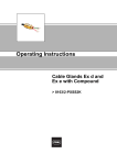
Operating Instructions
Cable Glands Ex d and
Ex e with Compound
> 8163/2-PX2K
Contents
1
Contents
1
2
3
4
5
6
7
8
9
10
11
12
2
Contents ................................................................................................................2
General Information ...............................................................................................2
General Safety Information ...................................................................................3
Designated Use .....................................................................................................4
Technical Data ......................................................................................................4
Transport, Storage and Disposal ...........................................................................5
Assembly ...............................................................................................................6
Commissioning ......................................................................................................9
Maintenance ..........................................................................................................9
Accessories and spare parts ...............................................................................10
Type Examination Certificate (Page 1) ................................................................12
Declaration of Conformity ....................................................................................14
General Information
2.1 Manufacturer
R. STAHL Schaltgeräte GmbH
Am Bahnhof 30
74638 Waldenburg, Germany
Phone:
Fax:
Internet:
+49 7942 943-0
+49 7942 943-4333
www.stahl.de
2.2 Information regarding the Operating Instructions
ID NO.:
139004 / 816360300200
Publication Code:
S-BA-8163/2-PX2K-02-en-07/08/2008
We reserve the right to make technical changes without notice.
2.3 Symbols Used
X
Z
X
)
Action prompt:
Describes actions to be carried out by the user.
Reaction symbol:
Describes the results or the reactions to the actions taken.
Bullet
Information symbol:
Describes the notes and recommendations.
Warning sign:
Danger from energised parts!
Warning sign:
Danger due to an explosive atmosphere!
2
Cable Glands
8163/2-PX2K
139004 / 816360300200
S-BA-8163/2-PX2K-02-en-07/08/2008
General Safety Information
3
General Safety Information
3.1 Safety Instructions for Assembly and Operating Personnel
The operating instructions contain basic safety instructions which are to be observed
during installation, operation and maintenance. Failure to observe these instructions can
place persons, plant and the environment at risk.
WARNING
Risk due to unauthorised work on the device!
Z Risk of injury and damage to equipment.
X Assembly, installation, commissioning and servicing work must only be performed by
personnel who are both authorised and suitably trained for this purpose.
Before assembly/commissioning:
X Read through the operating instructions.
X Give adequate training to the assembly and operating personnel.
X Ensure that the contents of the operating instructions are fully understood by
the personnel in charge.
X The national installation and assembly regulations (e.g. IEC/EN 60079-14) apply.
When operating the components:
X Ensure the operating instructions are made available on location at all times.
X Observe safety instructions.
X Observe national health and safety regulations.
X Servicing/maintenance or repair work which are not described in the operating
instructions must not be performed without prior agreement with the manufacturer.
X Any damage may render explosion protection null and void.
X Any alterations and modifications to the component impairing its explosion protection
are not permitted.
X Install and use the component only if it is undamaged, dry and clean.
If you have questions:
X Contact the manufacturer.
3.2 Warnings
Warnings are sub-divided in these operating instructions according to the following
scheme:
WARNING
Type and source of the danger!
Z Possible consequences.
X Measures to avoid danger.
They are always identified by the signal word “WARNING“ and sometimes also have a
symbol which is specific to the danger involved.
139004 / 816360300200
S-BA-8163/2-PX2K-02-en-07/08/2008
Cable Glands
8163/2-PX2K
3
Designated Use
3.3 Conformity to Standards
The cable glands comply with the following regulations and standards:
X Directive 94/9/EC
X IEC/EN 60079-0, IEC/EN 60079-1, IEC/EN 60079-7, IEC/EN 60079-15
X IEC/EN 61241-0, IEC/EN 61241-1
4
Designated Use
The cable gland is used to introduce permanently installed cables into electrical equipment of type of protection Increased Safety "e", Flameproof Enclosure "d", Restricted
Breathing "nR" and Protection by Enclosure "tD". It provides an inner, explosion-protected compound seal for the individual cable cores and ambient sealing for the cable outer
sheath. The cable gland provides an electrical connection via the armour termination.
It is approved for use in hazardous areas of zones 1, 2, 21 and 22.
WARNING
Only use the component for its intended purpose!
Z Otherwise, the manufacturer’s liability and warranty will be rendered void.
X Only use the component under the operating conditions described in the operating instructions.
X The component must be used in hazardous areas only according to these operating
instructions.
5
Technical Data
Explosion protection
ATEX
Zone 1 / 21
E II 2 GD Ex d IIC / Ex e II / Ex tD A21 IP66
Zone 2
E II 3 G Ex nR II
IECEx
Zone 1 / 21
Ex d IIC / Ex e II / Ex tD A21 IP66
Zone 2
Ex nR II
Certificates
ATEX
Zone 1 / 21
SIRA 06 ATEX 1188 X
Zone 2
SIRA 07 ATEX 4327 X
IECEx
IECEx SIR 06.0080 X
Type of Protection
IP66, IP67 & IP68 (10 m depth)
Version
BS 6121, EN 50262
Operating temperature range
- 60 °C ... + 100 °C
Material
4
Gland
Brass, nickel-plated brass, stainless steel
Seal
SOLO LSF
Cable Glands
8163/2-PX2K
139004 / 816360300200
S-BA-8163/2-PX2K-02-en-07/08/2008
Transport, Storage and Disposal
A
C
E
B
Dimensional drawings (all dimensions in mm) - subject to alterations
D
07596E00
Gland
size
Dimensions [mm]
Thread
size C
Inner
sheath A
Armour wire thickness
Max. no.
of cores
max.
20s/16
6
M20 x 1.5
12.6
15
Outer sheath B
min.
max.
6.1
11.5
Thread
length D
Across
corners E
Grooved
cone
Plain cone
15
33.3
0 ...1.0
0.90 ...1.00
20s
M20 x 1.5
12.6
15
9.5
15.9
15
33.3
0 ...1.0
0.90 ...1.25
20
M20 x 1.5
12.6
15
12.5
20.9
15
33.3
0 ...1.0
0.90 ...1.25
25s
M25 x 1.5
17.5
29
14.0
22.0
15
40.5
0 ...1.0
1.25 ...1.60
25
M25 x 1.5
17.5
29
18.2
26.2
15
40.5
0 ...1.0
1.25 ...1.60
32
M32 x 1.5
23.6
51
23.7
33.9
15
51.3
0 ...1.0
1.60 ...2.00
40
M40 x 1.5
30.0
80
27.9
40.4
15
61.0
0 ...1.0
1.60 ...2.00
50s
M50 x 1.5
36.6
122
35.2
46.7
15
66.5
0 ...1.0
2.00 ...2.50
50
M50 x 1.5
41.0
149
40.4
53.1
15
78.6
0 ...1.0
2.00 ...2.50
63s
M63 x 1.5
47.9
205
45.6
59.4
15
83.2
0 ...1.0
2.00 ...2.50
63
M63 x 1.5
53.7
259
54.6
65.9
15
89.0
0 ...1.0
2.00 ...2.50
75s
M75 x 1.5
59.9
320
59.0
72.1
15
101.6
0 ...1.0
2.00 ...2.50
75
M75 x 1.5
64.3
364
66.7
78.5
15
111.1
0 ...1.0
2.00 ...2.50
Transport, Storage and Disposal
Transport
X Shock-free in its original carton, do not drop, handle carefully.
Storage
X Store in a dry place in its original packaging
Disposal
X Ensure environmentally friendly disposal of all components according to legal regulations.
139004 / 816360300200
S-BA-8163/2-PX2K-02-en-07/08/2008
Cable Glands
8163/2-PX2K
5
Assembly
7
Assembly
)
We recommend the usage of a sealing ring between the enclosure wall and
the male union.
Overview
07600E00
1 Male union
2 Sealant tube
3a Smooth cone for wire armour cable (SWA)
3b Grooved cone for strip and tape armour as
well as braid cable
4 Armour sleeve
5 Adapter
6 Union nut
Preparing installation
07601E00
X Remove the cable outer sheath (7) and uncover the armour (8) and according to the
device geometry.
X Uncover armour over a length "L" (see table below).
6
Gland size
Length "L"
20S/16, 20S, 20
12 mm
25S, 25, 32, 40
15 mm
50S, 50, 63S, 63
18 mm
75S, 75, 90
20 mm
Cable Glands
8163/2-PX2K
139004 / 816360300200
S-BA-8163/2-PX2K-02-en-07/08/2008
Assembly
Installation
07605E00
X If necessary insert male union (1) into sealing ring.
X Screw male union (1) into enclosure (9).
07604E00
X Plug the cone (3) in correct position and according to the armour type into the male
union (1).
X Push cable (7) through male union (1).
X Slide the armour (8) over the cone.
07603E00
X Screw adapter (5) into male union.
Z Armour is fixed to cone.
07602E00
X Unscrew adapter (5) from male union.
139004 / 816360300200
S-BA-8163/2-PX2K-02-en-07/08/2008
Cable Glands
8163/2-PX2K
7
Assembly
07623E00
X Remove any coatings, fillers or tapes that protrude beyond the point "R".
X If the armour comprises individual wires, secure single wire armour with heat-shrink
sleeve or connect single wire armour to an insulated conductor.
Securing single wire armour with heat-shrink sleeve
X
X
X
X
Apply sealant over a length of 6 mm inside the cable.
Push heat-shrink sleeve (min. 100 mm) over the armour until it is against the sealant.
Carefully shrink heat-shrink sleeve onto the armour depending on type.
Ensure no air is trapped.
Connecting single wire armour to an insulated conductor
X
X
X
X
Uncover a further 15 mm of the outer sheath.
Open armour and splice with a screen conductor.
If necessary, shorten individual wires.
Crimp an insulated conductor to the screen conductors with an insulated crimp sleeve
or solder.
X Ensure the insulated conductor is long enough to reach the earthing point in the enclosure.
X Ensure there is at least 10 mm of sealant before and after the crimp connection.
Applying sealant
X
X
X
X
X
X
X
Separate conductors.
Apply sealant (10) between the conductors.
Push conductors together again.
Apply sealant around the conductors and in the cone.
Ensure the sealant is applied over a length "D" of at least 20 mm.
Ensure the amount of sealant reduces toward the sealant tube (2).
Push sealant tube (2) over sealant until it is in full contact with the cone.
07622E00
X Fill the end (11) of the sealant tube with sealant.
X Remove excess sealant (12).
8
Cable Glands
8163/2-PX2K
139004 / 816360300200
S-BA-8163/2-PX2K-02-en-07/08/2008
Commissioning
07603E00
X Screw adapter (5) into male union.
07603E00
X Tighten the union nut (6).
X Install the cable in the enclosure.
8
Commissioning
Before commissioning the device with the cable gland, make sure that
X
X
X
X
X
9
the cable gland is not damaged.
if necessary the sealing ring is present and mounted correctly.
unused holes are sealed by stopping plugs certified to Directive 94/9/EC.
the cables have been inserted correctly.
the bearing surfaces for the cable gland (sealing ring) are flat.
Maintenance
X Consult the relevant national regulations (e.g. IEC/EN 60079-17) to determine the type
and extent of inspections.
X Plan the intervals so that any defects in the equipment which may be anticipated are
promptly detected.
Check during maintenance:
X Compliance with the permitted temperatures in accordance with IEC/EN 60079-0.
X the cable glands for cracks.
X the seals for damage.
139004 / 816360300200
S-BA-8163/2-PX2K-02-en-07/08/2008
Cable Glands
8163/2-PX2K
9
Accessories and spare parts
10 Accessories and spare parts
WARNING
Use of non-approved accessories and spare parts.
Z The manufacturer’s liability and warranty will be rendered void.
X Use only original accessories and original spare parts manufactured by R. STAHL.
Designation
Illustration
Description
Order number
Weight
kg
PVC shroud
Sealing ring
04968T00
10
Cable Glands
8163/2-PX2K
Designation
Gland size
Across flats
Across
corners
HV04
20S/16 or
20S
24
26.6
109076
0.017
HV06
20
30.5
33.3
109078
0.024
HV09
25S or 25
37.5
40.5
109080
0.033
HV11
32
46
51
109082
0.040
HV15
40
55
61
109084
0.070
HV18
50S
60
66.5
109085
0.075
HV21
50
70
78.6
109086
0.230
HV23
63S
75
83.2
109094
0.117
HV25
63
80
89
109096
0.158
HV28
75S
89
101.6
109099
0.460
HV30
75
99
111.1
109101
0.400
––
Thread size
Minimum
thickness
Outer diameter
––
M16
2.0
25.4
167668
0.001
M20
2.0
28.6
111778
0.001
M25
2.0
35.0
111779
0.001
M32
2.0
44.5
111780
0.001
M40
2.0
50.8
167671
0.001
M50
2.0
65.0
167672
0.001
M63
2.0
76.2
167673
0.001
M75
2.0
95.0
167674
0.001
139004 / 816360300200
S-BA-8163/2-PX2K-02-en-07/08/2008
Accessories and spare parts
Designation
Illustration
Description
Order number
Weight
kg
Lock nut
To fasten the cable glands in through holes
––
For cable glands
05865E00
139004 / 816360300200
S-BA-8163/2-PX2K-02-en-07/08/2008
Type
Thread
size
Packing unit
Brass,
nickel-plated
M16 x 1.5
50
138383
0.135
Brass,
nickel-plated
M20 x 1.5
50
138389
0.241
Brass,
nickel-plated
M25 x 1.5
50
138395
0.348
Brass,
nickel-plated
M32 x 1.5
25
138401
0.267
Brass,
nickel-plated
M40 x 1.5
10
138407
0.218
Brass,
nickel-plated
M50 x 1.5
4
138413
0.109
Brass,
nickel-plated
M63 x 1.5
1
138418
0.054
Brass nickelplated
M 75 x 1.5
1
110877
0.151
Cable Glands
8163/2-PX2K
11
Type Examination Certificate (Page 1)
11 Type Examination Certificate (Page 1)
CERTIFICATION
SCHEDULE
EC TYPE-EXAMINATION CERTIFICATE
Sira 06ATEX1188X
Issue 2
iv) 8163/2-****-PX****-** series-Type ranges of Compound filled barrier cable glands
Coded:
II 2 GD
Ex d IIC/Ex e II
Ex d IIC
Ex e II
Ex tD A21 IP66
or
for PXSS2K
range ONLY
I M2
Ex d I/Ex e I
Ex d I
Ex e I
The 8163/2-****-PX****-** series Type ranges of barrier cable glands consist of a male-threaded
front entry component, fitted with a compound tube such that a spigot/combination joint is formed,
which is intended to screw into an entry point of its associated enclosure in accordance with relevant
codes of practice. The compound tube contains Cedesa EP2122 setting compound that effects a
flameproof seal around the cable cores passing through it and is retained by a spacer. The front entry
component to main body mating thread may be fitted with an optional ‘O’ ring seal to provide increased
ingress protection. Clamping of the armour or braid is effected by a combination of the front entry
component assembly and the different optional armour cone and reversible sleeve combinations within
the main body being fastened together. An outer seal nut, containing an Evoprene Super G621
elastomeric displacement sealing ring and a Nylon 6 ferrule, threads onto the main body and effects
environmental sealing onto the cable outer sheath.
Cable clamping is achieved with the outer seal arrangement.
Additional Specific Design options
•
•
•
•
The use of alternative armour clamping components specified by the cable gland type designation.
The various arrangements vary the cable gland suitability for differing armour or braided type
cables.
Alternative material of manufacture of the ferrule to be the same as the gland material.
The removal of the ATEX outer seal, nut and ferrule, along with the body component
manufactured without the external mating thread. The cable gland being suitable for S.W.A
armoured cables and is identified within type designation coding.
The use of the compound tube and spacer along with the manufacture of the front entry
component with a female mating thread, to couple to an alternative main body, skid washer, seal
and nut. The latter replacing other component parts. This variant being identified within type
designation coding.
The gland and seal sizes are determined by the entry thread and cable range take sizes. In addition
note that not all the information detailed in the table is applicable to both gland types. See individual
approval drawings.
This certificate and its schedules may only be
reproduced in its entirety and without change.
Sira Certification Service
Rake Lane, Eccleston, Chester, CH4 9JN, England
Page 11 of 14
Form 9400 Issue1
12
Cable Glands
8163/2-PX2K
Tel:
Fax:
Email:
Web:
+44 (0) 1244 670900
+44 (0) 1244 681330
[email protected]
www.siracertification.com
139004 / 816360300200
S-BA-8163/2-PX2K-02-en-07/08/2008
Type Examination Certificate (Page 1)
CERTIFICATION
1
TYPE EXAMINATION CERTIFICATE
2
Equipment intended for use in Potentially Explosive Atmospheres Directive 94/9/EC
3
Certificate Number:
Sira 07ATEX4327X
4
Equipment:
Ranges of Cable Glands (See Descriptions)
Issue:
2
5
Applicant:
R. STAHL Schaltgeräte GmbH
6
Address:
Am Bahnhof 30
74638 Waldenburg (Württ)
Germany
7
This equipment and any acceptable variation thereto are specified in the schedule to this certificate and
the documents therein referred to.
8
Sira Certification Service certifies that this equipment has been found to comply with the Essential
Health and Safety Requirements that relate to the design of Category 3 equipment, which is intended
for use in potentially explosive atmospheres. These Essential Health and Safety Requirements are given
in Annex II to European Union Directive 94/9/EC of 23 March 1994.
The examination and test results are recorded in the confidential reports listed in Section 14.2.
9
Compliance with the Essential Health and Safety Requirements, with the exception of those listed in the
schedule of this certificate, has been assessed by reference to:
EN 60079-0:2004
EN 60079-15:2003
10
If the sign “X” is placed after the certificate number, it indicates that the equipment is subject to special
conditions for safe use specified in the schedule to this certificate.
11
This TYPE EXAMINATION CERTIFICATE relates only to the design of the specified equipment, and not
to specific items of equipment subsequently manufactured.
12
The marking of the equipment shall include the following:
II 3 G
Ex nR II
Project Number
C. Index
51M16472
07
D R Stubbings BA MIET
Certification Manager
This certificate and its schedules may only be
reproduced in its entirety and without change.
Sira Certification Service
Page 1 of 12
Form 9400 Issue 1
139004 / 816360300200
S-BA-8163/2-PX2K-02-en-07/08/2008
Rake Lane, Eccleston, Chester, CH4 9JN, England
Tel:
Fax:
Email:
Web:
+44 (0) 1244 670900
+44 (0) 1244 681330
[email protected]
www.siracertification.com
Cable Glands
8163/2-PX2K
13
139004 / 816360300200
S-BA-8163/2-PX2K-02-en-07/08/2008