1
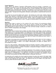
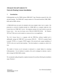
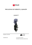
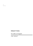
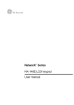
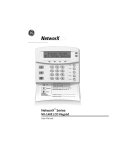
Installation and Operating Instructions Joystick III Last update: V2.20141208 3032258305-02-US Read and follow these operating instructions. Keep these operating instructions for future reference. Document Installation and Operating Instructions Product: Joystick III Document number: 3032258305-02-US Mueller-Electronics, Inc. P.O. Box 627 801 Clayridge Drive Wakarusa IN 46573 USA Phone: 855.634.7628 (855 – MEISOBUS) Fax: 574.862.2610 Email: [email protected] Website: http://www.mueller-electronics.com Table of contents Table of contents 1 Product description 4 2 Assembly instructions 5 2.1 Fitting a joystick with a D-Sub connector 5 2.2 Fitting a joystick with a CPC connector 5 3 Configuring the joystick 7 4 Operation 9 4.1 Executing functions 9 4.2 Changing the brightness of the LED 9 4.3 Assigning functions 9 4.4 Viewing functions 9 5 Technical specifications 11 5.1 Technical specifications of the joystick 11 5.2 D-Sub connector pin allocation 11 5.3 CPC connector pin allocation 11 5.4 Disposal 11 5.5 Information on the nameplate 12 6 Notes 13 3032258305-02-US V2.20141208 3 1 1 Product description Product description Joystick III Eight buttons Numbering of the buttons LED Side-mounted switch Manufacturer's plate [➙ 12] The joystick is an ancillary operating device which can rapidly access the functions of an ISOBUS job computer. The joystick is fitted with eight buttons and a single side-mounted switch, which enables switching between three levels. This enables the actuation of a total of 24 functions on the ISOBUS job computer. The current level is indicated by an LED. The joystick can be used to operate ISOBUS job computers which support the Auxiliary 1 or Auxiliary 2 protocols. Find out more about the protocol which you should choose here: [➙ 7] 4 3032258305-02-US V2.20141208 Assembly instructions Fitting a joystick with a D-Sub connector 2 2 Assembly instructions The joystick is available in two versions: ▪ With D-Sub connector (item no.: 3032258305) – Variant for vehicles with additionally installed ISOBUS basic equipment from MuellerElectronics. ▪ With CPC connector (item no.: 3032258606) – Variant for vehicles with integrated ISOBUS in-cab-connector. 2.1 Fitting a joystick with a D-Sub connector Mounting angle For attachment in the cab Connector for connection to the display Socket for connection to the basic vehicle harness Procedure You fit the joystick as follows: 1. Fit the joystick next to the driver on the right. 2. Plug the connector of the basic vehicle harness into the joystick socket. 3. Connect plug A of the joystick to the CAN bus socket of the display. For the majority of displays from Mueller-Electronics this is going to be the A socket. ⇨ The joystick now connects the basic vehicle harness with the display. 2.2 ⇨ When the display is switched on, the LED on the joystick lights up. Fitting a joystick with a CPC connector 3032258305-02-US V2.20141208 5 2 Assembly instructions Fitting a joystick with a CPC connector Mounting angle For attachment in the cabin Procedure Connector for connection to the vehicle's ISOBUS in-cab-connector You fit the joystick as follows: 1. Fit the joystick next to the driver on the right. 2. Plug the connector into the ISOBUS in-cab-connector of your vehicle. ⇨ The joystick is now connected to your vehicle. ⇨ When the vehicle is switched on, the LED on the joystick lights up. 6 3032258305-02-US V2.20141208 Configuring the joystick 3 3 Configuring the joystick Brightness for day or night mode: Day mode Selected auxiliary protocol Selected joystick number Cursor Function icon Meaning Switches between day and night mode Increase brightness Reduce brightness When configuring the joystick, you can make the following settings: ▪ Change the LED brightness in day and night mode. ▪ If you use several joysticks, select the joystick number. – The default value is "1". When using multiple joysticks, you must number these sequentially. ▪ Select the Auxiliary protocol. – "AUX1" Select this protocol when your ISOBUS job computer and your display support Auxiliary 1. You can then assign functions to the joystick. OR Select this protocol if you use an ME sprayer or a SECTION-Control BOX. – "AUX2" Select this protocol when your ISOBUS job computer and your display support Auxiliary 2. You can then assign functions to the joystick. If you don't know which protocol your system supports, you can test this by selecting protocol "AUX2". If you can then assign functions [➙ 9] for the ISOBUS job computer to the joystick, your system supports Auxiliary 2. Otherwise, select protocol "AUX1". Procedure To configure the joystick: The display is switched off. 3032258305-02-US V2.20141208 7 3 Configuring the joystick 1. Hold button 2 on your joystick pressed down. You can recognize button 2 from its white surround. 2. Start the display. 3. Release button 2 after approx. 5 seconds. 4. - Open the Joystick application. 5. Configure the joystick. 6. Restart the display. 8 3032258305-02-US V2.20141208 Operation Executing functions 4 4.1 4 Operation Executing functions Each button on the joystick can be assigned three functions. The position of the side-mounted switch determines the function which is performed when the button is pressed: Position of the switch Color of the LED Red Yellow Green Procedure To operate the joystick: 1. Move the side-mounted switch to the desired position and hold it securely. ⇨ The LED is lit in the appropriate color. 2. Press the button with the desired function. ⇨ The function will be activated. 3. Release the side-mounted switch and the button to exit the function. 4.2 Changing the brightness of the LED You can adjust the LED brightness to the daytime while working. You can choose from a day mode and night mode. Procedure To change the brightness of the LED: 1. Switch rapidly the side-mounted switch from its up position to the down position, or vice-versa. 4.3 ⇨ The LED mode will change. Assigning functions You assign ISOBUS job computer functions using the display. You can read how to do this in the operating instructions for the display. 4.4 Viewing functions Procedure To view the functions which are assigned to the joystick: You have selected the appropriate protocol when configuring the joystick. [➙ 7] Your ISOBUS job computer is connected to the vehicle's ISOBUS in-cab-connector. You have assigned functions to the joystick. [➙ 9] 1. Start the display. 3032258305-02-US V2.20141208 9 4 Operation Viewing functions 2. Open the selection menu. 3. - Open the Joystick application. ⇨ The following screen appears: ⇨ You can then see which joystick button has been assigned to an ISOBUS job computer function. The current level is shown on the right of the screen. 10 3032258305-02-US V2.20141208 Technical specifications Technical specifications of the joystick 5 5.1 5.2 5.3 5.4 5 Technical specifications Technical specifications of the joystick Parameter Value Operating voltage 10.5V to 16V DC Temperature range -4°F to +158°F Power consumption 40mA Protection rating IP20 D-Sub connector pin allocation Pin no. Signal Pin no. Signal 1 CAN_L_out 6 GND_E 2 CAN_L_in 7 CAN_H_in 3 CAN_GND 8 CAN_EN_out 4 CAN_H_out 9 +12VE 5 CAN_EN_in CPC connector pin allocation Pin no. Signal Pin no. Signal 1 Relay 6 TBC PWR (CAN_EN_in) 2 CAN_L_in 7 +12VE 3 CAN_L_out 8 CAN_GND 4 CAN_H_in 9 GND_E 5 CAN_H_out Disposal When it has reached the end of its service life, please dispose of this product as electronic scrap in accordance with all applicable waste management laws. 3032258305-02-US V2.20141208 11 5 5.5 Technical specifications Information on the nameplate Information on the nameplate The nameplate is located on the joystick. Abbreviations on the rating plate Abbreviation Meaning Customer number If the product was manufactured for an agricultural machinery manufacturer, the agricultural machinery manufacturer's item number will be shown here. Hardware version Mueller-Electronics item number Operating voltage The product may only be connected to voltages within this range. Software version Serial number 12 3032258305-02-US V2.20141208 Notes 6 6 Notes 3032258305-02-US V2.20141208 13