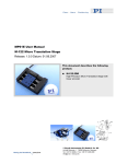
1
SM 148E Software Manual PIMikroMove® Release: 1.0.0 Date: 2005-11-28 This document describes software for use with most PI motion controllers © Physik Instrumente (PI) GmbH & Co. KG Auf der Römerstr. 1 ⋅ 76228 Karlsruhe, Germany Tel. +49 721 4846-0 ⋅ Fax: +49 721 4846-299 [email protected] ⋅ www.pi.ws Physik Instrumente (PI) GmbH & Co. KG is the owner of the following company names and trademarks: ® ® ® PILine , PI , PIMikroMove The following designations are protected company names or registered trademarks of third parties: Microsoft, Windows, LabView... Copyright 1999–2006 by Physik Instrumente (PI) GmbH & Co. KG, Karlsruhe, Germany. The text, photographs and drawings in this manual enjoy copyright protection. With regard thereto, Physik Instrumente (PI) GmbH & Co. KG reserves all rights. Use of said text, photographs and drawings is permitted only in part and only upon citation of the source. First printing 2005-11-28 Document Number SM 148E, Release 1.0.0 PIMikroMoveUserManual.doc This manual has been provided for information only and product specifications are subject to change without notice. This manual is superseded by any new release. The newest release is available for download at www.pi.ws About this Document Users of this Manual This manual is designed to help the reader to install and operate the PIMikroMove®.GUI software. It assumes that the reader has a fundamental understanding of basic servo systems, as well as motion control concepts and applicable safety procedures. This document is available as PDF file on the product CD. Updated releases are available via FTP or email: contact your Physik Instrumente Sales Engineer or write [email protected]. Conventions The notes and symbols used in this manual have the following meanings: WARNING Calls attention to a procedure, practice or condition which, if not correctly performed or adhered to, could result in injury or death. ! CAUTION Calls attention to a procedure, practice, or condition which, if not correctly performed or adhered to, could result in damage to equipment. NOTE Provides additional information or application hints. Related Documents The motion system hardware and other software tools which might be delivered with ® PIMikroMove are described in their own manuals. All documents are available as PDF files on the Motion CD or special product CD. Updated releases are available via FTP or email: contact your Physik Instrumente Sales Engineer or write [email protected]. Contents 1 Introduction 1.1 2 Getting Started ...........................................................................3 Main Window 2.1 3 WAC <command> <operator> <value> ................................... 23 MEX <command> <operator> <value>.................................... 24 MAC [N]START <name>.......................................................... 24 Example: Wait and Trigger....................................................... 24 Example: X-Y-Scan.................................................................. 25 Example: Pushbutton Control .................................................. 26 Command Entry Window..........................................................27 Position Pad Window ...............................................................29 2.6.1 2.7 Select Columns to be Displayed .............................................. 17 Sort rows .................................................................................. 17 Fields Displayed ....................................................................... 18 Axis Menu................................................................................. 21 Host Macros Tab Card .............................................................22 2.4.1 2.4.2 2.4.3 2.4.4 2.4.5 2.4.6 2.5 2.6 Connections Menu ..................................................................... 7 Controller Menu.......................................................................... 8 Tools Menu............................................................................... 11 Help Menu ................................................................................ 13 Toolbar .....................................................................................14 Axes Tab Card .........................................................................16 2.3.1 2.3.2 2.3.3 2.3.4 2.4 Position Pad Toolbar................................................................ 30 Single-Axis Window..................................................................31 Additional Windows 3.1 3.2 Axis Assignment....................................................................... 33 Profile Definitions for 2 Axes .................................................... 34 PI Tuning Tool ..........................................................................36 3.3.1 3.3.2 3.3.3 3.3.4 3.3.5 3.4 3.5 3.6 32 Move Multiple Axes ..................................................................32 Profile Generator ......................................................................32 3.2.1 3.2.2 3.3 6 Menu Bar....................................................................................7 2.1.1 2.1.2 2.1.3 2.1.4 2.2 2.3 3 Stage Setup Pane .................................................................... 37 Measurement Pane.................................................................. 37 Parameter-Tune Pane.............................................................. 37 Toolbar & Menus ...................................................................... 38 Autotune Option ....................................................................... 38 Preferences… ..........................................................................38 Demo Motion… ........................................................................39 Stage Editor .............................................................................40 Contents 3.6.1 3.6.2 4 Start up Controller 4.1 4.2 4.3 41 Connect Controller ...................................................................41 Select Connected Stages.........................................................42 Start Up Axes ...........................................................................43 4.3.1 5 Updating PIStages.dat ............................................................. 40 Updating User DAT Files ......................................................... 40 Advanced Startup..................................................................... 45 Tutorials – Frequently Asked Questions 47 Why do I need to “reference” an axis? ............................................... 47 Why is everything disabled when Command entry is active? ............ 47 My stage has limit switches, so why do I have to worry about crashing it? ......................................................................................... 48 How do I connect another controller to PIMikroMove®?..................... 48 How can I deactivate a connected stage? ......................................... 48 How do I add a controller to a controller network?............................. 48 How to use a stage that is not known to PIMikroMove® ..................... 49 How can I modify settings of a stage type in the PI stages database?........................................................................................... 49 I cannot find parameter xyz in the GUI............................................... 49 6 Appendix 6.1 50 Servo Algorithm and PID Tuning..............................................50 Introduction 1 Introduction Fig. 1: PIMikroMove® PIMikroMove® is a general-purpose graphical user interface for PI motion controllers. 1.1 Getting Started When PIMikroMove® starts, the Start up Controller dialog is displayed at the first step, Connect Controller. Here is where you connect controllers to PIMikroMove®. Fig. 2: Start up controller window at Step 1, Connecting controllers www.pi.ws PIMikroMove® SM 148E Release 1.0.0 Page 3 Introduction Only one controller may be selected at a time, but the dialog can be reopened from the Connections menu. See Section 4.1 for more information. After connecting a controller the window reopens at Step 2. Here you are given the opportunity to specify the stage types for the controller’s one or more axes. * Do not forget to click Assign to copy the selection from the stage list to the axis list. Fig. 3: Start Up Controller Step 2, shown just before clicking Assign to copy selected stage type (M-110.1DG) to selected axis slot (axis 4) See Section 4.2 for more information. When finished, click OK. * If the connected controller does not allow changing the connected stages, this step is skipped and window moves to Start up axes, Step 3. www.pi.ws PIMikroMove® SM 148E Release 1.0.0 Page 4 Introduction Fig. 4: Start up controller: Step 3, Start up axes, shown before referencing The window will reopen at the 3rd step, Start up axes, where you are given an opportunity to reference the axes connected. See Section 4.3 for more information. When this window is closed, Single-axis windows will open for the available axes. You may need to resize or move them to see the main window. www.pi.ws PIMikroMove® SM 148E Release 1.0.0 Page 5 Main Window 2 Main Window Fig. 5: PIMikroMove® main window The main window consists of several parts: Menu bar Toolbar Pane with tab cards for: o Axes o Macros (not shown: appears only if supported by one or more connected controllers) o Host Macros Some other windows can be shown, either as separate windows or docked into the main window: www.pi.ws PIMikroMove® SM 148E Release 1.0.0 Page 6 Main Window Fig. 6: Two Single-axis windows and the Position pad, all docked inside the main window with the Axes tab card displayed 2.1 Menu Bar Fig. 7: Menu bar 2.1.1 Connections Menu Fig. 8: Connections menu www.pi.ws PIMikroMove® SM 148E Release 1.0.0 Page 7 Main Window New… Opens the Start up Controller dialog (see p. 41) to connect another controller or controller network). Close Contains a submenu with entries for each connected controller/network. By selecting one of the menu entries, the connection to that controller can be closed. Note that the associated controller menu-bar item will disappear. Close all Closes connections to all connected controllers. All controller menu-bar items will disappear. Search for controller software Re-scan the local computer for PI software. This can be done after you have installed new controller software while PIMikroMove® is running. Exit Close all connections and exit PIMikroMove®. 2.1.2 Controller Menu For each connected controller or network of controllers there will be one controller entry in the menu bar. The text will indicate the class of controller and the items on the associated menu will depend on the controller class. For a C-843 controller the menu appears as shown. Note that some entries may be grayed out if the Command entry window is open. www.pi.ws PIMikroMove® SM 148E Release 1.0.0 Page 8 Main Window Fig. 9: Controller menu for a C-843 controller Select connected stages… Opens the Controller startup window at the Select stages step. Here you can tell the controller and the software what stages are connected. With most controllers, one entry is required for each motion axis. See Section 4.2 for more information. Start up axes… Opens the Controller startup window at the Start up axes step. See Section 4.3, p. 43 for more information. Tune stages … Opens the PITuningTool for the associated controller. With this tool you can easily determine well-suited parameters for P-I-D servo-controllers. See Section 3.3, p. 36 for more information. Profile Generator … Present if supported by the controller and required DLL found. Opens a series of dialogs for defining and executing certain types of user-defined motion profiles on two axes. Because the profiles are stored and executed on the controller side of the interface, the time resolution is much finer than when setting targets one at a time by command or host macro. See Section 3.2 p. 32 for details. www.pi.ws PIMikroMove® SM 148E Release 1.0.0 Page 9 Main Window Edit user stages data … Opens the PIStageEditor with the UserStages.dat file for the associated controller. (If you wish to examine entries in the read-only PIStages.dat, open the PIStageEditor from the Tools menu.) See the PIStageEditor Software Manual for details. Note that after leaving the Stage Editor any new or changed entries must be connected to PIMikroMove® in order to take effect. Add/Edit User Stage Type... Here, the current settings of a stage can be stored as a new stage type in the UserStages.dat file without the intricacies of the PIStageEditor. If the stage type already exists in the user section, its settings will be overwritten when the new ones are saved. You cannot change parameters for stages in the PI section, but you can download and install the latest version of PIStages.dat from www.pi.ws (see p. 40) Version info… Displays version info of the software used for the associated controller. Close connection Closes the connection to the associated controller or network. The associated controller menu, which will disappear completely from the menu bar, can be restored using the Connection → New menu sequence. www.pi.ws PIMikroMove® SM 148E Release 1.0.0 Page 10 Main Window 2.1.3 Tools Menu Fig. 10: Tools menu Move multiple axes... Opens dialog for initiating a synchronous move of more than one axis. Note the convenient shortcut to open/reopen this window: ^M. See Section 3.1, p. 32 for details. Demo Motion… Opens the Demo Motion… window: See Section 3.5, p. 39 for details. Stage Editor… Starts the PIStageEditor. From here you can inspect the parameters of all PI stages in the database as well as define and store special parameter sets for new or non-standard stages. See the PIStageEditor Manual for details. Show Position Pad Displays the Position Pad window, in which it is possible to control two axes using the mouse and or joystick. See Section 2.6, p. 29 for details. www.pi.ws PIMikroMove® SM 148E Release 1.0.0 Page 11 Main Window Show Command Entry Designed to give complete control of what is sent to the controller (for non-GCS controllers, to the controller GCS DLL). Here commands can be entered and responses seen. Because the software cannot allow itself periodic status or position checks in the background, other windows are not updated while the Command entry window is open. See Section 2.5, p. 27 for details. Show Single-Axis Window Opens a window in which data about a single axis is displayed and can be modified. The controller is interrogated at regular intervals (unless Command entry is open) to update the display. See Section 2.7, p. 31 for details. Show Digital I/O Window Shows a window in which the state of the digital input lines can be monitored and that of the digital output lines changed. The controller is interrogated at regular intervals (unless Command entry is open) to update the display. Show Analog Input Window Shows a window in which the state of the analog input lines can be monitored. The controller is interrogated at regular intervals (unless Command entry is open) to update the display. Preferences… Control the behavior of the software user interface. Some settings can not be undone the way they were made, such as turning off future appearances of confirmation dialogs. These settings can always be changed in the Preferences... window. www.pi.ws PIMikroMove® SM 148E Release 1.0.0 Page 12 Main Window Fig. 11: Preferences dialog Page Setup… Allows setting parameters which would be used for printing from the Command entry and Macro windows. 2.1.4 Help Menu PIMikroMove® has a comprehensive help system. Help Opens a standard help system with help relating to PIMikroMove®. FAQ, Tutorials... Task-oriented help for PIMikroMove®. About PIMikroMove® version information. www.pi.ws PIMikroMove® SM 148E Release 1.0.0 Page 13 Main Window 2.2 Toolbar Command entry Position pad PIStageEditor Search help Open help Demo motion Move multiple axes Context help Enter term to search Help on New connection Stop all axes Fig. 12: Main window tool bar New Connection Show the Start up Controller dialog to connect another controller or controller network to PIMikroMove®. See Section 4, p. 41 ff. for details. Move multiple axes Opens a dialog where targets and velocities for all on-target axes can be entered and the move of all desired axes started at the same time. See Section 3.1, p. 32 for details. Demo Motion Opens a dialog where ranges can be entered and random moves in that range started for demonstration purposes. See Section 3.5, p. 39 for details. PIStageEditor Opens the PIStageEditor where the stage parameters for all PI stages in the PIStages.dat and in the UserStages.dat data files can be examined. User stage parameters can also be edited. See the PIStageEditor Manual for details. www.pi.ws PIMikroMove® SM 148E Release 1.0.0 Page 14 Main Window Position Pad Displays the Position Pad window, in which it is possible to control two axes using the mouse pointer to specify the target positions, and/or the joystick to vary the velocities. See Section 2.6, p. 29 for details. Show command entry Opens the Command entry window where GCS ASCII commands can be typed in directly. While this window is open, PIMikroMove® performs no other communication with the controller, giving the user complete control. As a result, other windows are inactive and not refreshed. See Section 2.5, p. 27 for details. Search Help Searches for terms in PIMikroMove®’s comprehensive help system, which includes all of this manual. Open Help Opens a standard help system with help relating to PIMikroMove®. Context Help Answers the question “What’s this?” about the program element in question. Stop all axes Sends an immediate stop command (ASCII #24) to all axes connected to PIMikroMove®. The resulting motion profile is hardware dependent and not necessarily repeatable. www.pi.ws PIMikroMove® SM 148E Release 1.0.0 Page 15 Main Window 2.3 Axes Tab Card Fig. 13: Main window showing the Axes table Each axis of each connected stage is displayed in the axes table of the main window. You can specify the columns to be displayed and change the order of the rows (axes). You can also type new values into the white fields. If the target is changed, the system will move. Changed settings are not stored after PIMikroMove® closes. Stand-alone controllers will keep the changed settings until the next power on-off cycle. If you want to store the changed settings see “Add/Edit User Stage Type...” On the right side there is a small toolbar with the following functions to show and hide columns, re-sort the rows and otherwise configure the displayed values: Select columns to display — Reorder rows displayed — Help for Axes tab card — Fig. 14: Axes tab card vertical tool bar www.pi.ws PIMikroMove® SM 148E Release 1.0.0 Page 16 Main Window 2.3.1 Select Columns to be Displayed Fig. 15: Select columns Here you can select which axis-related fields are to be displayed. You also can change the order of the displayed columns with the arrow buttons (top is left, bottom is right). Fields depending on axis motion are updated when the window is active. 2.3.2 Sort rows The Sort rows window allows changing the order of the displayed rows. “Sort by controller” will sort the axes first by controller and then alphabetically by name. The arrow buttons allow moving the selected axis up or down in the list. Fig. 16: Sort Rows www.pi.ws PIMikroMove® SM 148E Release 1.0.0 Page 17 Main Window 2.3.3 Fields Displayed www.pi.ws Header Comments Name Axis designator Stage Stage type Controller Controller or controller network to which the axis is connected Target Current target position |< Move to minimum position < Perform relative step in negative direction Step size Size used for relative steps > Perform relative step in positive direction >| Move to maximum position Position Current position Stop Click to stop axis State State of axis Min. position Minimum position Max. position Maximum position Velocity Velocity to use during moves Max. velocity Limit for velocity Servo Servo state Pos. limit Indicates whether positive limit signal is active Ref. switch Indicates whether current position is above or below reference point Neg. limit Indicates whether negative limit signal is active Find neg. lim. Move in negative direction until negative limit switch trips, then back off limit; can be used to reference an axis PIMikroMove® SM 148E Release 1.0.0 Page 18 Main Window Header Comments Find reference Move toward the reference point until reference signal changes state; if state went from high to low, the process is repeated; can be used to reference an axis Find pos. lim. Move in positive direction until positive limit switch trips, then backs off limit; can be used to reference an axis P-Term Servo-algorithm “proportional” term I-Term Servo-algorithm “integral” term D-Term Servo-algorithm “differential” term I-Limit Limit on contribution of the I-term Kvff (Velocity feed forward) Kout (output scale factor) Bias (motor bias) Maximum position error Maximum value for the motor output Maximum allowed velocity Maximum allowed acceleration Maximum allowed deceleration Maximum allowed Jerk Numerator of the counts per physical unit factor Entry as fraction makes it easier to specify certain values, like those from gearboxes. Denominator of the counts per physical unit factor Output mode Can be either “PWM” or “DAC” (analog) Invert the direction Scale factor www.pi.ws Can be used to command the axis in non-metric units (e.g. for inches, set to 25.4) PIMikroMove® SM 148E Release 1.0.0 Page 19 Main Window Header Comments Rotary stage Stage has a reference Maximum travel range in positive direction Value at reference position Distance from the negative limit to the reference position Axis limit mode Limit switches active high / active low Stage type Stage has brake Profile mode Indicates the current profile mode: Trapozoid, S-curve or User Profile Mode P-Term 2 Servo-algorithm 2nd “proportional” term I-Term 2 Servo-algorithm 2nd “integral” term D-Term 2 Servo-algorithm 2nd “differential” term I-Limit 2 Limit on contribution of the 2nd Iterm Kvff 2 (Velocity feed forward) Kaff 2 (Acceleration feed forward) Servo 2 Window Maximum travel range in negative direction Invert the reference Has limit switches Limit switches present/absent Motor offset pos. Motor offset neg. Settle Window www.pi.ws PIMikroMove® SM 148E Release 1.0.0 Page 20 Main Window Header Comments Settle I-Limit Settle time Kvff 3 Window Kvff 3 (Velocity feed forward) Kaff (Acceleration feed forward) 2.3.4 Axis Menu Fig. 17: Axis menu The Axis menu can be displayed by clicking the triangle in the first column of the axes grid, by right-clicking anywhere in the corresponding row or by right-clicking on any free area in the Single-Axis Window. www.pi.ws Show/Hide Single-axis window This will toggle display of the corresponding Single-axis window Define home position Makes the current physical position the home position of the axis. The current position is set to 0 Move to home position Moves the corresponding axis to its home position by setting the target to 0 Initialize axis Initialize the corresponding axis and can sometimes move it off limit a switch PIMikroMove® SM 148E Release 1.0.0 Page 21 Main Window 2.4 Clear error Shows current error code with explanation and, if possible, returns the axis or axes to a non-error state Host Macros Tab Card Fig. 18: Host macro tab card with no macros open Host macros allow you to store a sequence of commands in a text file for later execution by a connected controller. The left side of the panel has a list with the currently open host macro files, the right pane is a text field where the commands can be composed and changed. Toolbar buttons are available for creating, opening and saving the macro command sequences. You can also specify that the macro command sequence will be executed repeatedly a certain number of times when the macro is run (Repeat). A fixed execution delay can also be specified between the command lines in the Delay [ms] field: PIMikroMove® will then wait that amount of time between sending each line. (Note: On Windows systems, the time resolution is about 10 ms, so you will notice no difference between a delay of 5 and 10 ms!) www.pi.ws PIMikroMove® SM 148E Release 1.0.0 Page 22 Main Window The individual lines of the macro are sent as-is with no syntax checking before being sent on, except for the four special commands that are interpreted by PIMikroMove® directly: WAC ONT? <command> <operator> <value> waits until the specified axis condition occurs (see 2.4.1) MEX <command> <operator> <value> stops macro execution when a given condition is fulfilled (see 2.4.2) DEL <delay in milliseconds>” waits for the specified time MAC START <name> calls another host macro. MAC NSTART <name> <rp_val> calls another host macro and runs it rp_val times (see 2.4.3) When a command starts a longer process on the controller (e.g. a move to the reference switch) the execution of the macro is paused as long as this takes place. You do not need to use WAC to wait for such a process to finish. In this version of PIMikroMove®, all commands in a given host macro must address the same controller or controller network. It is not currently possible to address controllers on different interfaces inside one macro, even if the connections are open and the axis identifiers unique. 2.4.1 WAC <command> <operator> <value> WAit until a given Condition of the following type is fulfilled: The condition involves comparing a specified value with the result of a command that returns one value on one line. <command> is the command in its full syntax. The command must be one that provides a response consisting of one single value on one line. <operator> is the comparison operator; supported are “=” “<=” “<” “>” “>=” “!=” <value> is the value to be used on the right side of the comparison. For example: with WAC ONT? 1 = 1 you can wait for axis 1 to be on target. WAC DIO? A = 1 waits for the digital input A to be high. WAC POS? B > 4 waits for axis B to reach a position greater than 4. www.pi.ws PIMikroMove® SM 148E Release 1.0.0 Page 23 Main Window 2.4.2 MEX <command> <operator> <value> Stop macro execution when a condition of the following type is fulfilled. The condition involves comparing a specified value with the result of a command that returns one value on one line. When the macro interpreter accesses this command for execution the condition is checked. If it is true the macro is stopped, otherwise the macro execution continues with the next line. Later fulfillment of the condition will not in itself trigger any action. <command> <operator> <value> is the command in its full syntax. The command must be one that provides a response consisting of one single value on one line. is the comparison operator; supported are “=” “<=” “<” “>” “>=” “!=” is the value to be used on the right side of the comparison For example: MEX DIO? A = 0 will exit the macro if the digital input A is 0. 2.4.3 MAC [N]START <name> With MAC START you can call another macro. <name> specifies the filename of the text file with the macro content. With MAC NSTART you can specify how many times the called macro should be run. Thus you can implement loops by placing the commands of the loop inside a separate macro file and calling it with MAC NSTART (see sample below). 2.4.4 Example: Wait and Trigger Example of how to send a trigger signal after the motion of an axis has finished. Put the logic of waiting and triggering in a macro named WAITTRIG and call it after each MOV or MVR command. Macro waittrig.txt: WAC ONT? A = 1 DIO A1 DEL 100 DIO A0 www.pi.ws PIMikroMove® SM 148E Release 1.0.0 Page 24 Main Window You can use this in other macros: MOV A10 MAC START WAITTRIG MOV A0 MAC START WAITTRIG 2.4.5 Example: X-Y-Scan Example of loops implemented with MAC NSTART: All three macros together will perform a 10 x10 mm scan. At each target point during the scan one of the digital outputs is set high for 100 ms to trigger an external device. Macro scanxy.txt: This macro will move the two axes A and B to their home positions and wait for both axes to stop. Then the macro scanrow.txt is called 10 times. GOH AB WAC ONT? A = 1 WAC ONT? B = 1 MAC NSTART SCANROW 10 Macro scanrow.txt: This macro will move axis A 1 mm and wait for it to stop. Then the macro scanstep.txt is called 10 times. At the end, axis B is moved back to its home position. MVR A1 WAC ONT? A = 1 MAC NSTART SCANSTEP 10 GOH B WAC ONT? B = 1 Macro scanstep.txt: This macro will move axis B 1 mm, wait for it to stop and set the digital output A to 1 for 100 milliseconds. MVR B1 WAC ONT? B = 1 DIO A1 DEL 100 DIO A0 www.pi.ws PIMikroMove® SM 148E Release 1.0.0 Page 25 Main Window 2.4.6 Example: Pushbutton Control If you have connected four push buttons to 4 digital inputs you can implement pushbutton control of five different macros using the “MEX” command. The following example illustrates a small program: you can move axis A 1 mm forward or backward with button 1 and 2 and you can switch between two velocities with buttons 3 and 4. Macro KEYPBLOOP.txt This macro will call the macros for the individual buttons and then call itself MAC START KEYPB1 MAC START KEYPB2 MAC START KEYPB3 MAC START KEYPB4 MAC START KEYPBLOOP Macro KEYPB1.txt This macro will exit if digital input A (keyPB 1) is not active, otherwise a relative move of 1 mm is made for axis A. The short delay prevents this macro being called too rapidly when the button is pressed MEX DIO? A = 0 MVR A1 DEL 100 Macro KEYPB2.txt This macro will exit if digital input B (keyPB 2) is not active, otherwise a relative move of -1 mm is made for axis A. The short delay prevents this macro being called to rapidly when the button is pressed MEX DIO? B = 0 MVR A-1 DEL 100 Macro KEYPB3.txt This macro will exit if digital input C (keyPB 3) is not active, otherwise the velocity is set to 0.5. The short delay prevents this macro being called too rapidly when the button is pressed MEX DIO? C = 0 VEL A0.5 DEL 100 www.pi.ws PIMikroMove® SM 148E Release 1.0.0 Page 26 Main Window Macro KEYPB4.txt This macro will exit if digital input D (keyPB 4) is not active, otherwise the velocity is set to 1.5. The short delay prevents this macro being called too rapidly when the button is pressed MEX DIO? D = 0 VEL A1.5 DEL 100 2.5 Command Entry Window Fig. 19: Command entry window Here you can address GCS commands directly to a controller or controller network without any background processing done by PIMikroMove® (for non-GCS controllers, commands are translated in a software DLL layer outside of PIMikroMove®). For detailed descripitions of the commands, see the GCS Commands Software Manual. These descriptions are also available in the PIMikroMove online help system. In addition, the response to the HLP? command consists of a listing of all commands and their arguments. The Command entry screen gives you complete control over anything that is sent to the controller and shows all the controller’s responses. www.pi.ws PIMikroMove® SM 148E Release 1.0.0 Page 27 Main Window For this reason, all other controls are disabled as long as the Command entry window is open. (See “Why is everything disabled when Command entry is active?,” p. 47). The left pane shows the history of all commands sent. When the cursor is placed in the Send text field, the contents of that field will be replaced by commands in the history list if you press the ↑ or ↓ arrow keys; pressing any other key returns you to the Send text, where you can edit the command before sending. Four frequently used commands or command sequences are accessable with the F5, F6, F7 and F8 keys or buttons. To edit a sequence, hold down the control key while pressing the key or clicking the button. The contents of the clipboard can be sent as-is with Send clipboard. To change the font and color of sent and received messages, use the Configure style button. It also allows you to switch off the display of the strings sent, so only received messages are shown. It is also possible to send single bytes directly through to the controller, controller network, or controller DLL. To do so, enter a “#” followed by the decimal value of the ASCII character. For example “#24” will send the byte with value 24 (^X), which is interpreted by most controllers to stop all axes and macros. If you need to send “#” as a character itself, type “##” or “#35” www.pi.ws PIMikroMove® SM 148E Release 1.0.0 Page 28 Main Window 2.6 Position Pad Window Fig. 20: Position Pad With the position pad you can control and visualize the position of two axes. .The black cross marks the target position and the blue cross the current position. In Target control mode, you can click or drag the target position with the mouse or you can move it with the joystick. The left side of the window shows the toolbar and the position grid. On the right side you can choose which two axes to control and see their position, target and velocity settings. To change the velocity use the corresponding single-axis windows or the Axes Tab Card. The Position Pad can be docked to the bottom border of the main window (see Fig. 6) www.pi.ws PIMikroMove® SM 148E Release 1.0.0 Page 29 Main Window 2.6.1 Position Pad Toolbar Origin and directions Top left Joystick control Swap X,Y Bottom left Pseudo-vector move Top right Bottom right Help Velocity control Target control Fig. 21: Position pad toolbar www.pi.ws The first four buttons are mutually exclusive and specify the orientation of the coordinate system. When Pseudo-vector moves is activated, the velocities are set so that both axes arrive at the target at approximately the same. With Swap X and Y axes you can interchange the display position of the both axes. When Target control is activated, you can set a target by clicking with the mouse. You can move the target (before or after the axes have reached it) either by dragging it with the mouse or by using the joystick. When Velocity control is activated, you use the joystick to set the current speed and direction. The maximum velocity components are the limits that were in force when Velocity control was activated. It is not possible to set targets with the mouse in this mode. PIMikroMove® SM 148E Release 1.0.0 Page 30 Main Window 2.7 Single-Axis Window Fig. 22: Single-axis window The Single-axis windows show a single axis and allow to control target, velocity and step size. If you right-click on any free area in the window you can access the Axis Menu for the axis displayed in the window. The Single-axis windows can be docked to the left or right border of the main window (see Fig. 6). www.pi.ws PIMikroMove® SM 148E Release 1.0.0 Page 31 Additional Windows 3 Additional Windows Note that windows which are in any way controller-specific are accessible from the corresponding controller menu rather than from the Tools menu. Some can also be opened with a key combination or toolbar button. 3.1 Move Multiple Axes Fig. 23: Move multiple axes The Move multiple axes window allows starting a move of several axes by clicking a single button. You can configure which axes will be moved, their targets and velocities. The start of the moves will not be synchronized if they are connected to different controllers. Axes connected to the same controller will be synchronized, to the extent the controller supports synchronous moves. 3.2 Profile Generator The Profile Generator menu item is on the controller menu of supporting controllers (e.g. C-843). It gives access to some of the complex motion profile functions of supporting controllers (if the required controller-specific DLL is not present, this menu item will not appear) * With motion profiles it is possible to specify in more detail what happens while one or more axes move from their current position to a new one. When a special mode of the motion controller is used, a much finer time resolution is possible than by sending discrete move commands over an interface. With * GCS commands are also available that give more complete access to User Profile Mode. Using them, specification of the desired trajectories is tedious and must be done with great care, but profiles can be freely defined for all axes. www.pi.ws PIMikroMove® SM 148E Release 1.0.0 Page 32 Additional Windows multi-axis systems, this also provides an easy way to specify motion along a specific trajectory. A simple type of motion profile for a single axis can be defined by a set of time and position value pairs. In that definition, the axis takes the amount of time specified in the first pair to move from the first position to the position in the next pair, etc. To make the motion smoother, velocity specifications can be added, expanding the pairs to sets of 3 values. Profiles with up to 5 specified values in each set are supported: time, position, velocity, acceleration and jerk (the rate of change of acceleration). Interpolation between the specified values is performed by the motion control chip. With five-value data sets, a cubic spline interpolation is possible. 3.2.1 Axis Assignment When the Profile generator item on the controller menu is selected, the Profile axes dialog box appears. Fig. 24: Axis assignment for User Profile Mode In it, you specify two axes to be used in User Profile Mode and how to display the resulting profiles in the X-Y plane on the next screen. Only referenced axes with servo on will be available in the lists for the Profile generator. www.pi.ws PIMikroMove® SM 148E Release 1.0.0 Page 33 Additional Windows 3.2.2 Profile Definitions for 2 Axes Fig. 25: User profile definition window for circular-type motion In the User profile definition window, sinewave motion profiles for two axes are defined. When run synchronously and visualized on an X-Y plane, the resulting motion forms a circle, ellipse or Lissajoux figure, depending on the user-specified parameters. The graph at the left of the window is made from the time and position values in the profiles generated for the two axes. In the display the positions are shown connected by straight lines, but the motion controller does a cubic spline interpolation between them. www.pi.ws PIMikroMove® SM 148E Release 1.0.0 Page 34 Additional Windows The user parameters to be entered have the following meanings: Steps/360 for a true circle, the number of points in time per each 360 degrees of motion, for which the profiles contain explicit values for axis position, velocity, acceleration and jerk. * Interpolation is used for the motion between the specified positions. Start angle for a true circle, the angular coordinate of the starting point.* Travel angle for a true circle, the difference between the angular coordinate of the last position specified and the first position specified.* Wrap around if activated, motion continues from the last to the first position specified. Radius Lissajous X, Y if both equal, then an ellipse (or circle) is generated, otherwise a Lissajous figure with the corresponding frequency ratio. Stretch X, Y relative scaling in the X and Y directions (must be equal for a circle) Speed factor is multiplied times the maximum velocity of the slower axis to give the speed at which to trace the figure, after start-up and before slow-down. Cannot be > 1 Accel. factor factor by which the maximum acceleration is further reduced. Cannot be > 1 Decel. factor factor by which the maximum deceleration is further reduced. Cannot be > 1 OK close the window and, after optional confirmation, start the motion (PIMikroMove® will send the appropriate GCS commands to the controller). Cancel the window is closed without any motion being performed. a linear scale factor applied on top of Stretch X & Y. * In the general case, the angular position is the phase angle of the corresponding point on one of the single-axis sinewave components, divided by that axis’ Lissajoux factor. www.pi.ws PIMikroMove® SM 148E Release 1.0.0 Page 35 Additional Windows 3.3 PI Tuning Tool Fig. 26: PITuningTool window with servo-loop parameters The PI Tuning Tool, available on the controller menu of supporting controllers, is designed to determine reasonable servo-control parameters for the different axes on the controller. While the stage moves stepwise, real-time positions are recorded and displayed. After a step the stage is automatically moved back to the starting position. Fig. 27: Additional tuning parameters The additional tuning parameters are passed to the Profile Generator (if supported) as constraints for the profiles it generates. www.pi.ws PIMikroMove® SM 148E Release 1.0.0 Page 36 Additional Windows 3.3.1 Stage Setup Pane Select your stage type from the list. Use DEFAULT_STAGE or DEFAULT_STAGE-P (the same except that Motor mode is set to PWM) for stages not listed or if you do not want to be subject to any restraints like limits, reference positions, etc. CAUTION It is not necessary to reference the stage, but you are responsible for not driving the stage into its limits! Add/Save adds a new entry to the list of stage types or refreshes an existing entry. Note: The entries are saved automatically in the controller-specific Userstages.dat file which is located in the \GCSTranslator directory. It is not possible to modify parameters stored in the PIstages.dat file which contains the factory-defined stage settings. 3.3.2 Measurement Pane Check the box to end recording automatically the specified amount of time after the motion has finished. When unchecked you can set the total time of recording. If you are working with the DEFAULT_STAGE, the step size is in counts, otherwise it is in physical units (e.g. millimeter). A minus sign in the Step size line reverses the direction of motion. Adjust the value according to your specific application. With the Move Rel. button you can move the stage by the Step size value without recording any data. Sample rate defines how many motion processor cycles are skipped until another data point is stored in the controllers internal memory and displayed in the graphics pane afterwards. Set to zero except for long recording times. 3.3.3 Parameter-Tune Pane Moving the sliders changes the P, I and D parameters. Once a slider is activated (click on it and you will see a dashed border around it) use the right/left keys for fine adjustment. Use the number fields to the right to define the slider ranges. Alternatively you can enter values directly in the left handed number fields. A value is not adopted until you press Enter. If the value is outside of the slider range, the range limit will be set to this new value. Load factory settings retrieves the stagespecific values from the pistages.dat file, Load default settings calls the parameters used for the DEFAULT_STAGE. www.pi.ws PIMikroMove® SM 148E Release 1.0.0 Page 37 ! Additional Windows 3.3.4 Toolbar & Menus Use the buttons from the toolbar to show/hide the cursors and the cursor information pane and to choose the tool used within the graphics pane respectively. A short description will be displayed if the mouse cursor hovers over a button. In the cursor information window the absolute values of the difference are displayed. You cannot move the cursors to negative time values. With the Axes menu you can change the current axis and arrange the windows for the individual axes. It is recommended to not move several axes at the same time. 3.3.5 Autotune Option Automatic tuning is available as a password-protected option which can be purchased before or after initial delivery. To use it to calculate P, I and D values automatically, click the Autotune button in the lower right and enter your password. Autotuning will, of course, move the axis. Fig. 28: Example of autotune results For additional manual tuning methods and a description of the servo-algorithm used, see the Appendix, p. 50 ff. 3.4 Preferences… Controls the behavior of the software user interface. In particular, the requirement for confirmation of various actions can be turned on or off. Note that the confirmation dialog boxes themselves have a checkbox to turn off future appearances of the dialog, but the Preferences... window is the only place to turn them back on. www.pi.ws PIMikroMove® SM 148E Release 1.0.0 Page 38 Additional Windows Fig. 29: Preferences window 3.5 Demo Motion… Opens the Demo Motion window: Fig. 30: Demonstration-motion window The controls are self-explanatory. Note that the white bar in the Current position field for each axis serves as a graphic representation of the axis’ position. While this window is active, the Stop buttons in other windows are ineffective. You can switch between two different motion modes: www.pi.ws Random moves (within the given range) Full-range moves in alternating directions, i.e. back and forth between the specified minimum and maximum positions. PIMikroMove® SM 148E Release 1.0.0 Page 39 Additional Windows 3.6 Stage Editor Opens the PIStageEditor, a tool that permits examining the stage names and parameters values in the PIStages data files. Two types of DAT files are recognized by PIMikroMove® and the PIStageEditor, protected (read-only) DAT files with data from PI about all available stages, and User DAT files, containing special parameter sets created or customized by the user. See the PIStageEditor software manual for detailed information. 3.6.1 Updating PIStages.dat To install the latest version of PIStages.dat from the PI Website proceed as follows: 3.6.2 1 On the www.pi.ws front page, click on Download/Support in the Service section on the left 2 Click on Download in the navigation bar across the top (no login or password is required) 3 Click on the General Software category 4 Click on PI Stages 5 Click the download button below PIStages.dat 6 In the download window, switch to the ...\PI\GcsTranslator directory. The location of the PI directory is that specified upon installation, usually in Program files or Programme (may differ in otherlanguage Windows versions) 7 If desired, rename any existing PIStages.dat so as to preserve a copy for safety reasons 8 Download the file from the server as PIStages.dat Updating User DAT Files Use the PIStageEditor to view and edit entries in User DAT files. To simply store the current, active parameters under a new stage name in a user DAT file, consider using Edit User Stages Data choice on the controller menu as a simpler alternative to the stage editor (see p. 8). www.pi.ws PIMikroMove® SM 148E Release 1.0.0 Page 40 Start up Controller 4 Start up Controller This section explains how to connect a controller or set of networked controllers to PIMikroMove® and how to start up the connected stages. The following dialog is shown at start of PIMikroMove®, and appears after a number of different menu sequences. You can show this dialog later with New connection on the toolbar or with the menu sequence Connections→New… The startup procedure typically contains three steps: 4.1 1 Connect Controller, see p. 41 2 Select Connected Stages, see p. 42 3 Start Up Axes, see p. 43 Connect Controller This section contains a detailed description of the windows introduced in the “Getting Started” section. Fig. 31: Startup Controller window with Connect Controller (Step 1) selected www.pi.ws PIMikroMove® SM 148E Release 1.0.0 Page 41 Start up Controller The list box in the middle of the window shows symbols for all controllers known to the host system. Select the first controller you want to use and choose the correct interface settings (baud rate, COM port, IP address, …) and click “Connect”. PIMikroMove® tries to establish a connection to the controller as specified. If this is successful, the Select connected stages dialog is shown automatically. Please note that not all of the interfaces shown may be physically present on your system. With Version info you can show the versions of the software components found by PIMikroMove®. This information can be helpful in diagnosing problems with PIMikroMove®. (PIMikroMove® searches once at startup for controller software. If you want to search again or show the version info at a later time, use the Connections→Search for controller software menu sequence.) 4.2 Select Connected Stages Fig. 32: Startup Controller window with Select connected stages (Step 2) selected With this dialog you can select the types of the connected stages for the various axes. It shows two lists: www.pi.ws PIMikroMove® SM 148E Release 1.0.0 Page 42 Start up Controller The list of connected axes with stage types (left) The list of all stage types known to the controller (right) If you cannot find the entry for a PI stage in this list download the latest version of PIStages.dat from the PI Website (see p. 40) If you want to connect a non-PI stage, see “How to use a stage that is not known to ”. The following actions can be performed in this window: Disconnect a stage from an axis: single-click (highlight) it and press the No stage button. Replace a stage type with another: highlight its line in the left list, and double-click the new stage type in the list at the right (or highlight it and click the Assign button). Accept the list of connected axes/stages (and store the corresponding parameter values on the controller): press the Apply or OK button. OK also closes the window and displays the Start up axes window. Return the left list to the initial or last accepted state: press Reset or Cancel. Cancel also closes the window. Manipulate the list of stage types on the right: right-click in the list and call up the PI Stage Editor. It is needed if you want to add a stage to the list of known stages, for example a new stage from PI or a non-PI stage. See the Stage Editor User Manual for more information. You can return to the Select stages window with the Select stages item on the controller menu of the corresponding controller or controller network. 4.3 Start Up Axes Almost all systems require that the axes be initialized before normal use. For systems with incremental position sensors, this includes determining the absolute position of each axis (referencing). Referencing is usually done by driving the motor slowly until a reference or limit switch with a known position is reached, or, if the absolute current position is known not to have changed since having been saved on the host, it can be restored, or, if it is otherwise known, it can be entered manually. www.pi.ws PIMikroMove® SM 148E Release 1.0.0 Page 43 Start up Controller Fig. 33: Startup Controller window with Start up axes (Step 3) selected Neg. limit, Pos. limit, and Ref. switch buttons are for a reference move of the selected (highlighted) axis or axes. If any of the selected axes does not support a given type of referencing (e.g. has no reference switch), the respective button will be dimmed. Restore is available if the state is Unreferenced and positions were saved on the host PC the last time the connection to the controller was closed. ! CAUTION When using Restore, be sure that the affected axes have not moved in any way since the positions were saved. The saved position will be used as the current absolute position and will be the base of all future calculations and range checks. If the stage has moved in between and the value is no longer correct, you can easily crash the stage. For more information see Why do I need to “reference” an axis?, p. 47. If you need more control or you cannot move the stage to one of the known positions, call the Advanced startup dialog by pressing “Advanced…” You can return to this window by selecting Start up axes... in the controller menu of the corresponding controller. www.pi.ws PIMikroMove® SM 148E Release 1.0.0 Page 44 Start up Controller 4.3.1 Advanced Startup Fig. 34: Advanced startup of selected stages This dialog gives you more control about the startup of the stages. In this example Move to Reference is dimmed because some of the selected stages do not have a reference switch. You have the following options not available on the previous screen: www.pi.ws Define absolute position: Inform PIMikroMove® (and thus the motion controller) manually where the axes currently are. This makes absolute positioning possible and the status will be set to on target. Note that the numeric value entered is interpreted as axis working units. Relative moves only: abandon absolute positioning. When this is done, all range checks are switched off PIMikroMove® SM 148E Release 1.0.0 Page 45 Start up Controller ! CAUTION ! CAUTION If you define the absolute position manually, be sure to choose the correct value. This will be the base of all future calculations and range checks. If the value specified is wrong, you can easily crash the stage. If you choose to enable relative moves only, no more range checks are performed. You can easily crash the stage. For more information see “Why do I need to “reference” an axis?” and “My stage has limit switches, so why do I have to worry about crashing it?” www.pi.ws PIMikroMove® SM 148E Release 1.0.0 Page 46 Tutorials – Frequently Asked Questions 5 Tutorials – Frequently Asked Questions This chapter contains some general information useful in understanding the background of PIMikroMove® and answers some frequently asked questions. It also has a collection of short recipes for accomplishing common tasks. Why do I need to “reference” an axis? To move a stage to an absolute position the motion controller needs to know the current position. Many stages, however, have only relative sensors (encoders) that are used to determine the current position. Somehow the controller must find out where the stage is. This can be done by moving to a known fixed position. PIMikroMove® uses a limit or reference switch to define such a known point. (The reference position is the point where the reference signal changes polarity.) If a stage has no limit switch or reference signal, or the stage cannot move to any of these positions without damaging the system, you can either enter the current absolute position directly, or—if the current application does not need it—you can operate using relative moves only, i.e. without absolute positions. To reference an axis by moving to a known point, to enter the current absolute position or to start the axis in relative move mode use the Start up axes dialog. Why is everything disabled when Command entry is active? When the Command entry tab card is on top, all other controls containing data regarding the selected controller are disabled (Single-axis windows, Position pad, …). This is done to avoid confusion between the commands entered in the terminal and background processing done by PIMikroMove® (PIMikroMove® must continuously check the state of the axes and the controller). www.pi.ws PIMikroMove® SM 148E Release 1.0.0 Page 47 Tutorials – Frequently Asked Questions For example, if you want to find out how a specific command works and your entered command contains a typo or invalid data, then the controller does nothing. To find out what went wrong, you can check the error state with ERR?. If background activity had been taking place, however, the error state would have been cleared in the meantime. The Command entry pane is designed to give you more control over what is sent to and received from the controller. My stage has limit switches, so why do I have to worry about crashing it? To avoid sacrificing valuable travel range, limit switches are sometimes installed very close to the hard stop. If run into the limit switch at maximum speed, especially with a load on the platform, the momentum can cause the stage to crash into the hard stop even if the motor shuts down immediately. How do I connect another controller to PIMikroMove®? To connect another controller or controller network to PIMikroMove® you do not need to close any existing connections. You can connect as many controllers as you have connected to your PC. Simply call the Start up controller dialog with the Connections → New... menu sequence or the New connection button on the toolbar. How can I deactivate a connected stage? To deactivate an axis, choose Select connected stages from the corresponding controller menu (p. 8). In the window that opens, select the axes to be deactivated or disconnected and press the NOSTAGE button. The axis will disappear from the axes table and, if open, the corresponding axis window will be closed. The effect of deactivating an axis in motion or an axis executing a controller macro may vary. How do I add a controller to a controller network? Certain types of controllers can be networked together and all controlled off one interface on the host PC (e.g C-862, C-170, C-662). PIMikroMove® typically treats such controller networks as a single, multi-axis controller. See the controllers’ User Manuals for instructions on configuring such a network. www.pi.ws PIMikroMove® SM 148E Release 1.0.0 Page 48 Tutorials – Frequently Asked Questions How to use a stage that is not known to PIMikroMove® All PI stages with their parameters are stored in the PIStages database. If your PI stage is not in the list, please contact PI to get an update. If you want to connect a stage that is not from PI, select DEFAULT_STAGE or DEFAULT_STAGE-P from the list. This choice corresponds to a stage with the following characteristics: No limit switches, No reference switch Axis unit of 1 encoder count Motor output is set to analog mode (DEFAULT_STAGE) or PWM mode (DEFAULT_STAGE-P) Note that you can start the axis only by entering the absolute position or by choosing to allow relative moves only (usually in the Start up axes dialog). The units for all moves, positions, and accelerations will have encoder counts. If you have changed all settings and can work with your stage, you can save the settings as a new stage type to the user section of the stages database. To add a new stage to the user section of the stages database, see Add/Edit User Stage Type... or use the PIStageEditor (called by the Edit User Stages Data menu entry, see also “User Stages” in the PIStageEditor software manual). How can I modify settings of a stage type in the PI stages database? If you want to modify the parameters of an existing stage type and use the modified settings with other PI software outside PIMikroMove® you can add a new stage type to the user section of the stages database. Thereafter you can select the newly defined stage in other PI software as well. Simply call Add/Edit User Stage Type... for the corresponding axis. I cannot find parameter xyz in the GUI. If you want to view or modify a certain parameter of the axes, or you are missing a function it maybe only hidden from display. If you want to change the set of displayed parameters and functions see “Select Columns to be Displayed.” www.pi.ws PIMikroMove® SM 148E Release 1.0.0 Page 49 Appendix 6 Appendix 6.1 Servo Algorithm and PID Tuning The PID closed-loop control technique compares the actual position measured by the position sensor with the desired target and adjusts the output to the drive accordingly. On PI motor controllers, this technique is implemented by the following algorithm: n ⎡ ⎤ Ki ) + K aff (CmdAccel × 8)⎥ × K out + Bias Output = ⎢ K p E n + K d (E k − E (k −1) ) + ∑ E j × 256 + K vff ( CmdVel 4 j =0 ⎣ ⎦ 65536 where: • Kp is a gain factor which is multiplied by the error signal (the difference between actual and desired position) for proportional control. It acts as an adjustable amplifier and is responsible for process stability. If Kp is increased the error is more quickly corrected. However, if Kp becomes too large, the mechanical system will begin to overshoot, and at some point, it may begin to oscillate, becoming unstable if it has insufficient damping. Proportional gain affects all frequencies. • Ki is a gain factor which is multiplied by the sum of the error signal accumulated over the time for integral control. Ki is allows to eliminate steady-state errors, but large values or usage without proper damping could cause severe system oscillations. Integral action increases gain as frequency decreases. • Kd is a gain factor which is multiplied by the rate of change of the following error signal. Kd is responsible for system response and may be thought of as electronic damping. Increasing the value of Kd, increases the stability of the system. The steady-state error, however, is unaffected since the derivative of the steady-state error is zero. Derivative action increases gain as frequency increases and thus amplifies any noise in the error signal. www.pi.ws PIMikroMove® SM 148E Release 1.0.0 Page 50 Appendix There are many methods to identify the combination of the Kp, Ki and Kd gain factors which achieves the desired closed-loop performance, e.g. elementary methods, informal methods (quarter-wave decay, minimum overshoot, maximum disturbance rejection) and mathematical methods (IAE, ISE, ITAE, ITSE). Further reading is recommended. The PI Tuning Tool facilitates use of a live trial method in conjunction with the Ziegler-Nichols tuning method. CAUTION Foresee and mitigate any risks that may be caused by variations in operation from tuning experiments. Live trial method: Enter an initial set of tuning parameters from experience. Press Run loop. Watch the step responses in the graph pane and dynamically adjust the PID terms in increments of about 5%. Fig. 35: Live trial method Ziegler-Nichols open-loop tuning method: Set Ki and Kd to zero and decrease Kp until you get a motion error. The controller is now in “manual mode” (i.e. without feedback). Press Single step. www.pi.ws PIMikroMove® SM 148E Release 1.0.0 Page 51 ! Appendix Fig. 36: Ziegler Nichols Ziegler and Nichols determined that the best settings for the tuning parameters could be computed from T, d, and K as follows: Kp = 1 .5 ⋅ T Kd Ki = Kp 2.5 ⋅ d K d = − 0 .4 ⋅ K p d Ziegler-Nichols closed-loop tuning method: Set Ki and Kd to zero to shut off the integral and derivative corrections. Press Run loop. Increase Kp until any disturbance causes a sustained oscillation: www.pi.ws PIMikroMove® SM 148E Release 1.0.0 Page 52 Appendix Fig. 37: Sustained oscillation Hint: Place first cursor on first rising edge and second cursor on fifth rising edge of the oscillation curve. Adjust second cursor such the horizontal cursor lines cover each other. (This ensures phase equality.) The smallest controller gain that causes such an oscillation is called the ultimate gain Ku. The appropriate tuning parameters can be computed as follows: K p = 0.75 ⋅ K u www.pi.ws Ki = Kp 0.625 ⋅ P K d = − 0 .1 ⋅ K p P PIMikroMove® SM 148E Release 1.0.0 Page 53 MS77E User Manual C-843 Release: 2.5.0 Motor Controller Card Date: 2006-03-21 This document describes the following product(s): C-843.21 Motor Controller Card (PCI), 2 motor axes C-843.41 Motor Controller Card (PCI), 4 motor axes © Physik Instrumente (PI) GmbH & Co. KG Auf der Römerstr. 1 ⋅ 76228 Karlsruhe, Germany Tel. +49-721-4846-0 ⋅ Fax: +49-721-4846-299 [email protected] ⋅ www.pi.ws Declaration of Conformity according to ISO / IEC Guide 22 and EN 45014 Manufacturer: Manufacturer´s Address: Physik Instrumente (PI) GmbH & Co. KG Auf der Römerstrasse 1 D-76228 Karlsruhe, Germany The manufacturer hereby declares that the product Product Name: Model Numbers: Product Options: Motor Controller Card C-843 all conforms to the following EMC Standards and normative documents: Electromagnetic Emission: EN 61000-6-3, EN 55011 Electromagnetic Immunity: EN 61000-6-1 Safety (Low Voltage Directive) : EN 61010-1 Electrical equipment which is intended to be integrated in other electrical equipment only conforms to the cited EMC Standards and normative documents, if the user ensures a compliant connection when implementing the total system. Possible necessary measures are installation of the component in a suitable shielded enclosure and usage of suitable connectors. March 14, 2005 Karlsruhe, Germany Dr. Karl Spanner President Physik Instrumente (PI) GmbH & Co. KG is the owner of the following company names and trademarks: PI®, ActiveDrive™ The following designations are protected company names or registered trademarks of third parties: Windows, LabView Copyright 1999–2006 by Physik Instrumente (PI) GmbH & Co. KG, Karlsruhe, Germany. The text, photographs and drawings in this manual enjoy copyright protection. With regard thereto, Physik Instrumente (PI) GmbH & Co. KG reserves all rights. Use of said text, photographs and drawings is permitted only in part and only upon citation of the source. First printing 2006-03-21 Document Number MS77E, Release 2.5.0 C-843_User_MS77E.doc This manual has been provided for information only and product specifications are subject to change without notice. About this Document Users of this Manual This manual is designed to help the reader to install and operate the C-843 Motor Controller Card. It assumes that the reader has a fundamental understanding of basic servo systems, as well as motion control concepts and applicable safety procedures. The manual describes the physical specifications and dimensions of the C-843 Motor Controller Card as well as the software and hardware installation procedures which are required to put the associated motion system into operation. This document is available as PDF file on the product CD. Updated releases are available via FTP or email: contact your Physik Instrumente sales engineer or write [email protected]. Conventions The notes and symbols used in this manual have the following meanings: WARNING Calls attention to a procedure, practice or condition which, if not correctly performed or adhered to, could result in injury or death. DANGER Indicates the presence of high voltage (> 50 V). Calls attention to a procedure, practice or condition which, if not correctly performed or adhered to, could result in injury or death. CAUTION Calls attention to a procedure, practice, or condition which, if not correctly performed or adhered to, could result in damage to equipment. NOTE Provides additional information or application hints. Related Documents The stage / motor and the software tools which might be delivered with the C-843 Motor Controller Card are described in their own manuals. All documents are available as PDF files on the Motion CD or special product CD. Note that here is no special manual available for the GCS_COM library. Refer to the GCS_DLL Manual (MS 112E) for function descriptions. Updated releases are available via FTP or email: contact your Physik Instrumente sales engineer or write [email protected]. ! Contents 1 Introduction 1.1 1.2 1.3 1.4 1.5 2 3 Purpose of the C-843 .................................................................4 Safety Precautions .....................................................................4 Unpacking ..................................................................................6 Additional Components ..............................................................7 System Requirements ................................................................8 Quick Start 2.1 2.2 2.3 2.4 4 Configuration Settings for Multiple Cards.................................22 4.2 Architecture .............................................................................. 24 Communication ........................................................................ 24 Command Sets ........................................................................ 25 PIStages Database .................................................................. 26 GUI Applications ...................................................................... 26 Tools to Use .............................................................................27 Technical Data 5.1 24 General ....................................................................................24 4.1.1 4.1.2 4.1.3 4.1.4 4.1.5 5 Connector Locations ................................................................ 18 Motor Connector Pinouts ......................................................... 19 Digital I/O Connector................................................................ 20 All-axis Connector .................................................................... 21 Software Overview 4.1 15 Output Current Limitation .........................................................16 Motor Output Modes.................................................................17 On-Board Memory....................................................................18 Connectors and Pinouts ...........................................................18 3.4.1 3.4.2 3.4.3 3.4.4 3.5 9 Install the Software on Host PC .................................................9 Install the Card in Host PC .......................................................10 Begin Operation .......................................................................12 Uninstalling and Updating ........................................................14 System Description 3.1 3.2 3.3 3.4 3 28 Low-Level Information ..............................................................29 5.1.1 5.1.2 5.1.3 5.1.4 Digital I/O Lines ........................................................................ 29 Analog Amplifier and Brake Control......................................... 29 Sense of Limit Switch and Reference Signals ......................... 29 Encoder Signals ....................................................................... 29 Contents 5.1.5 5.1.6 Index and Home Reference Signals ........................................ 30 All-axis Connector .................................................................... 30 Introduction 1 Introduction The C-843 is a 2- or 4-channel Motor Controller, designed as a PCI plug-in board that can be used in any PC with a free PCI slot. With the software on the C-843 CD, it can control any combination of DC Motors and PI Voice Coil Stages. * The board is available in a 2-axis and a 4-axis version: C-843.21 Motor Controller for 2 axes C-843.41 Motor Controller for 4 axes C-843 features at a glance: PCI-bus-compatible PC board Analog amplifiers for 5 W motors Selectable PWM output (10-bit resolution, 24.5 kHz) Full P-I-D motion control Multiple trajectory profile generation Profile modes: trapezoidal, S-curve, user specified Incremental encoder input (differential) Limit switch control Motor brake support for each axis High-level command language 8 TTL input and 8 TTL output channels Software DLL for C, C++, Visual Basic 64 kword on-board RAM for high-precision, userspecified trajectory profile control * Control of PILine® Piezomotors requires special software, as provided and described on the separate C-843PM CD. www.pi.ws C-843 MS77E Release 2.5.0 Page 3 Introduction 1.1 Purpose of the C-843 The C-843 with the included hardware and software drivers is designed to drive DC motors and PI Voice Coil Drives in any combination up to a total power consumption of about 20 watts. Five-watt motors can be driven directly from the integrated amplifiers. More powerful motors need external amplifiers. All C-843s can also control compatible PILine® piezomotors, but special software is required; that software is included with the C-843.PM versions, which come with different manuals and a different product CD. The C-843 is based on a fast DSP processor providing highperformance PID motion control with many options for trajectory generation and filter setting. The motors can be controlled as to position, velocity, acceleration and many other motion-relevant parameters. Incremental rotary encoders or linear scales are used for position feedback. To operate the C-843, it must be part of a motion system consisting of a host PC and at least one motorized axis (stage). The card itself and the appropriate software must be installed in a PC with Windows operating system (Win 98, ME, NT, 2000, XP) and a free PCI slot. 1.2 Safety Precautions NOTE The C-843 Motor Controller Card does not contain any user-serviceable parts of adjustment elements. DANGER Failure to heed warnings in this manual can result in bodily injury or material damage. DANGER Before opening the host PC, remove the line-voltage connection. Heed any warnings provided by the manufacturer of the PC or of other add-on cards it may contain. www.pi.ws C-843 MS77E Release 2.5.0 Page 4 Introduction WARNING The C-843 Motor Controller Card is an ESD-sensitive (electrostatic discharge sensitive) device. Observe all precautions against static charge buildup before touching this device. Avoid touching circuit components, pins and PCB traces. Discharge any static charge you may have on your body by briefly touching a conductive, grounded object before you touch any electronic assembly. Pose PCBs only on conductive surfaces, such as ESD-safe transport containers (envelopes, foam). Electronic subassemblies must always be kept and transported/shipped in conductive packaging. Make sure that no conductive particles of any kind (metallic dust or shavings, broken pencil leads, loose screws) get on the card or into the PC Make sure that no electrical contact between the various add-on cards in the PC is possible. All motion of the connected motors and mechanical stages is software controlled, and software may fail. Be aware that some motorized stages can generate large forces which can cause personal injury or other damage if not properly handled. ! CAUTION DO NOT EXCEED MAXIMUM CURRENTS! Keep in mind that the total current for the C-843 is supplied from the PC power supply only. Extreme power peaks will occur when: Motors accelerate or decelerate very fast Motors are reversed at high speed Motors stall Stages are driven into the hard stop www.pi.ws C-843 MS77E Release 2.5.0 Page 5 Introduction The total current may exceed the current capability of the PC power supply. Voltage drops may occur with the risk of PC malfunction or damage to other devices such as hard disks drives. The C-843 has factory-set output current limitation. Nevertheless the user has to ensure that the total current does not exceed the capability of the PC power supply. 1.3 Unpacking WARNING The C-843 Motor Controller Card is an ESD-sensitive (electrostatic discharge sensitive) device. Observe all precautions against static charge buildup before touching this device. Avoid touching circuit components, pins and PCB traces. Discharge any static charge you may have on your body by briefly touching a conductive, grounded object before you touch any electronic assembly. Pose PCBs only on conductive surfaces, such as ESD-safe transport containers (envelopes, foam). Electronic subassemblies must always be kept and transported/shipped in conductive packaging. Unpack the C-843 Motor Controller Card with care. Compare the contents against the sales contract and packing slip. The following components should be included: www.pi.ws C-843.x1 Motor Controller Card Separate mounting bracket with sub-D 25 connector for the digital I/O lines 5.25-inch-style, 4-wire power Y-connector With C-843.41 cards only: separate mounting bracket with two 15-conductor sub-D connectors for motors #3 and #4 C-843 distribution CD containing host software, hardware driver and all manuals as PDF files (for an overview over the host software see p.24) C-843 MS77E Release 2.5.0 Page 6 Introduction Standard version of the C-843 User Manual (this document) in printed form User Manual for PIMikroMove® software in printed form Inspect the contents for signs of damage. If parts are missing or you notice signs of damage contact PI immediately. Save all packing materials in the event the product needs to be reshipped. 1.4 Additional Components Depending on your application, you might need the following unincluded items for use with the C-843 Controller Card: C-843.JS option (for use with LabView VIs and PIMikroMove® operating software): joystick and sound card with game port C-842.AP1 PWM to analog adapter box, for driving analog stages with high power consumption using an external PWM amplifier Contact your PI sales engineer or write [email protected], if you need additional components. www.pi.ws C-843 MS77E Release 2.5.0 Page 7 Introduction 1.5 System Requirements To start working with the C-843 Motor Controller card, your motion system needs to meet the following conditions: A PC with a free PCI slot to install the C-843 Windows operating system (Win 98, ME, NT, 2000, XP) One or more motorized positioners with incremental encoders (e.g. a linear, rotary, or voice coil stage or a DC-Mike; controlling a PILine® piezo motor requires special software drivers included and described on the piezomotor version of the product CD, C-843PM.CD) Cables to connect stage and controller (PI cable order numbers: C-815.35 or C-815.36) We recommend that you make your first trials with the C-843 using the PIMikroMove® software package. This is the quickest way to verify that your system is connected and operating properly. You can even run simple automation tasks with the PIMikroMove® macro facility. All information about PIMikroMove® is found in a separate manual, which is included both in printed form and on the C-843 CD. www.pi.ws C-843 MS77E Release 2.5.0 Page 8 Quick Start 2 Quick Start With a motion system that meets the requirements listed above, carry out the following steps to put it into operation: 1 Install the drivers and software on host PC (see p.9) 2 Install the card, with the PC powered completely down (see p. 10) 3 Begin operation (see p. 12) If C-843 or C-843PM host software is already installed, it must be uninstalled before the new version can be installed. To uninstall, follow the instructions on p. 14. 2.1 Install the Software on Host PC For a short description of the available host software see Section 4.2 on p.27. 1 Be sure to log in with administrator privileges and insert the C-843 CD in the host PC. 2 If the Setup Wizard does not start automatically, start it from the root directory of the CD with the www.pi.ws icon. 3 Follow the on-screen instructions. You can choose between “typical” and “custom” installation. Typical components are hardware driver, LabView drivers, DLLs and PIMikroMove®. “Typical” is recommended. 4 Shut down the PC. C-843 MS77E Release 2.5.0 Page 9 Quick Start 2.2 Install the Card in Host PC WARNING The C-843 Motor Controller Card is an ESD-sensitive (electrostatic discharge sensitive) device. Observe all precautions against static charge buildup before touching this device. Avoid touching circuit components, pins and PCB traces. Discharge any static charge you may have on your body by briefly touching a conductive, grounded object before you touch any electronic assembly. Pose PCBs only on conductive surfaces, such as ESD-safe transport containers (envelopes, foam). Electronic subassemblies must always be kept and transported/shipped in conductive packaging. Make sure that no conductive particles of any kind (metallic dust or shavings, broken pencil leads, loose screws) get on the card or into the PC. Make sure that no electrical contact between the various add-on cards in the PC is possible. DANGER Before opening the host PC, remove the line-voltage connection. Heed any warnings provided by the manufacturer of the PC or of other add-on cards it may contain. www.pi.ws 1 Turn off the host PC and unplug the line cord. Then open the PC housing. 2 With C-843.41 only: to use motor axes #3 and #4 of the C-843.41, you must connect the two ribbon cables of the included 2-connector bracket adapter to the corresponding 16-pin header connectors on the C843.41 board (for component locations see Fig. 1). 3 Optional: to make the digital I/O lines of the C-843 available (see section 3.4.3 on p. 20), you must connect the ribbon cable of the included sub-D-25 bracket adapter to the 26-pin Digital I/O header on the C-843 board (for component locations see Fig. 1). C-843 MS77E Release 2.5.0 Page 10 Quick Start 4 Remove the slot covers from the positions in the PC which you plan to use. 5 For multiple-card installations: make sure the card numbers are properly configured in EEPROM (see p. 20 before continuing). 6 Install the C-843 card in a free PCI slot; install any adapter brackets you connected in steps 2 and 3 in suitable (neighboring) positions. 7 Screw down the card and any adapter brackets. Otherwise the card may creep out of its connector or the adapters will slip and may cause a short circuit. 8 Connect the C-843 to the PC internal power supply (see Fig. 2). If there is no free cable of sufficient length from the power supply, use the Y-cable which comes with the card as a splitter or as an extension. 9 Close the PC case. Axis 3 & 4 header connectors Digital IO connector and ribbon cable Axis 3 & 4 connectors and ribbon cables Digital IO header Motor power input Cable from PC power supply or Y-connector Fig. 1: C-843 and connectors www.pi.ws C-843 MS77E Release 2.5.0 Page 11 Quick Start Fig. 2: C-843.41 installed, with power connector at lower right 2.3 Begin Operation CAUTION ! DO NOT EXCEED MAXIMUM CURRENTS! Keep in mind that the total current for the C-843 is supplied from the PC power supply only. Extreme power peaks will occur when: Motors accelerate or decelerate very fast Motors are reversed at high speed Motors stall Stages are driven into the hard stop www.pi.ws C-843 MS77E Release 2.5.0 Page 12 Quick Start The total current may exceed the current capability of the PC power supply. Voltage drops may occur with the risk of PC malfunction or damage to other devices such as hard disks drives. The C-843 has factory-set output current limitation. Nevertheless the user has to ensure that the total current does not exceed the capability of the PC power supply. 1 Restart the host PC. 2 When the New Hardware Wizard appears, do the following: 1st window: click Next 2nd window (Win XP only): Do not connect to Windows Update to search for software Next window: Do not search, but choose the option that will display a list of drivers and click Next Next window: in the Model list pane, “C843 Device Driver” should be highlighted. Otherwise click Have Disk and select the CD-ROM drive with the C-843 CD and the path \Driver\Win(your operating system)\c843[...].inf, then click Next Next window: click Next Next window: click Finish Note that this procedure is required, even though the hardware driver was already installed with the setup procedure in Section 2.1. www.pi.ws 3 Connect the stages to the sub-D15 connectors in the mounting bracket(s). Be sure to note the channel designations; the labels on the brackets correspond to the axis or motor numbers used in PIMikroMove®. Other software may count starting from 0 instead of 1. 4 If you have chosen the corresponding option, PIMikroMove® will now start as soon as the C-843 Device Driver is running. If not, you can start it manually and use its buttons and menus to command the connected axes. See the PIMikroMove® software manual for details. C-843 MS77E Release 2.5.0 Page 13 Quick Start 2.4 Uninstalling and Updating NOTE Software that is no longer supported (e.g. PISmart) may be removed by the uninstall procedure and cannot be reinstalled from the new CD. To uninstall the C-843 host software use the StartÆSettingsÆControl PanelÆAdd/Remove Programs (Software) menu sequence and follow the on-screen instructions. To update the C-843 host software proceed as follows: www.pi.ws 1 If you want to keep any existing configuration files, save them under new names or in a new directory 2 Uninstall the old C-843 host software version using the StartÆSettingsÆControl PanelÆAdd/Remove Programs (Software) menu sequence (This also removes unneeded directories) 3 Install the new C-843 host software version by running the Setup Wizard from your update CD 4 If desired, move back any configuration files you saved in step 1 C-843 MS77E Release 2.5.0 Page 14 System Description 3 System Description The C-843 Motor Controller is designed for high-performance motion control based on the MC2140 (MC2120) Advanced Multi-Axis Motion Control chipset (for detailed descriptions see the Motion Processor manuals on the C-843 CD). The board is designed as a 32-bit, plug-and-play, PCI-bus card, compatible with main boards with 3.3 V and 5 V PCI bus slots (universal card). Read/Write operations are controlled via the PCI bus and memory-mapped PCI bridge, providing fast data transfer for complex motion control. The C-843 provides closed-loop digital servo-control for a large variety of servo-motors. It uses incremental encoder position feedback signals. Sophisticated trajectory profile and digital servo capabilities are provided for each axis, resulting in very low position and velocity tracking errors. Axes can be programmed either independently or synchronously to allow advanced multi-axis motion, such as tracing circular and other complex path profiles. For motor amplifier output the C-843 has one on-board linear amplifier per motor axis; each amplifier is capable of driving a 5 W motor. PWM outputs for external amplifiers are also available. The chipset’s integrated 64 k-word trace memory allows online tracing of up to four independent system variables (positions, velocities, internal register contents, etc.) at whole-number multiples of the servo-loop time. To offer maximum flexibility, software interfaces at a number of different levels are provided and documented. In most cases, higher-level interfaces also provide pass-through functions for lower-level commands. See “Software Overview,” p. 24 for more details. www.pi.ws C-843 MS77E Release 2.5.0 Page 15 System Description 3.1 Output Current Limitation CAUTION ! DO NOT EXCEED MAXIMUM CURRENTS! Keep in mind that the total current for the C-843 is supplied from the PC power supply only. Extreme power peaks will occur when: Motors accelerate or decelerate very fast Motors are reversed at high speed Motors stall Stages are driven into the hard stop The total current may exceed the current capability of the PC power supply. Voltage drops may occur with the risk of PC malfunction or damage to other devices such as hard disks drives. The C-843 has factory-set output current limitation. Nevertheless the user has to ensure that the total current does not exceed the capability of the PC power supply. All output channels have separate current limiting. The factory default output current limit for each channel is 1 A, sufficient to drive a 5 W motor. It is possible to drive stages with higher power consumption in PWM mode. See section 3.2 on p. 17. Each analog power amplifier can be enabled or disabled independently from the others. See “Analog Amplifier and Brake Control,” p. 29 for the hardware details. www.pi.ws C-843 MS77E Release 2.5.0 Page 16 System Description 3.2 Motor Output Modes The motor output mode and thus the amplifier mode can be set by command for each axis separately. Possible modes are “16bit DAC” (analog mode) * and “Sign/Magnitude PWM” (see the Motion Processor Users Guide p. 53 ff. for more information). The “50/50 PWM” mode of the motion processor chip is not presently supported by PI stages and thus not recommended. Nor is driving stepper motor stages currently possible with the C-843. Use the SPA command (GCS command set) to set the output mode (see the GCS Command Manual for the command description). Note: When working with the operating software provided on the product CD, the correct motor output mode for the selected stage is automatically set based on information in the internal stage database. Axes connected to a given C-843 card may be in different modes, so that PWM and analog stages can be run off the same card. When PWM mode is used, the stages are driven by external amplifiers instead of the C-843 on-board amplifiers, thus allowing higher-power stages. PWM mode is required with PI ActiveDrive™ stages (.PD and .DD models). If you want to drive an analog stage whose power consumption might exceed the output current limitation (see Section 3.1 on p. 16) a PWM converter box (C-842.AP1) can be used. The output mode of the appropriate axis must then be set to Sign/Magnitude PWM (or the stage with the “PWM” name suffix must be selected from the appropriate stage database). * In analog mode, commanding the motor to run in positive direction puts a higher voltage on the “MOT+” output than on the “MOT - ” output. Commanding the motor to run in negative direction puts a lower voltage on the “MOT+” output than on the “MOT - ” output. The maximum differential is 12 V and no particular relationship to ground is guaranteed. www.pi.ws C-843 MS77E Release 2.5.0 Page 17 System Description 3.3 On-Board Memory The motion processor chipset has what its documentation calls “external” memory on the card which is accessable in real time by the motion processor. This fact is exploited in User Profile Mode, making it possible to define and trace highly precise, multi-axis motion profiles without transmission delay uncertainties. In addition it is possible to access this memory independent of the trace function, thereby allowing it to be used for storage of information like product configuration. The C-843 is equipped with 64 kB of memory for this purpose. 3.4 Connectors and Pinouts 3.4.1 Connector Locations I/O Connector Motor #1 All Axes MC2140 IO Motor #2 MC2140 CP PCI Bridge Fig. 3: C-843 Board layout www.pi.ws C-843 MS77E Release 2.5.0 Page 18 System Description 3.4.2 Motor Connector Pinouts Connectors for Motors #3 & #4 (only on C-843.41) IDC16 header Pin 1 2 3 4 5 6 7 8 9 10 11 12 13 14 15 16 Connectors for Motors #1 & #2 (on bracket) Sub-D15f 1 9 2 10 3 11 4 12 5 13 6 14 7 15 8 Function Motor Brake Motor (+) Motor (-) GND MAGN SIGN Output + 5 V Negative limit Positive limit REFS GND Encoder A (+) Encoder A (-) Encoder B (+) Encoder B (-) n.c. For the C-843.41 an adapter mounting bracket is provided with two sub-D 15 connectors to allow standard-connector access for motors #3 and #4. www.pi.ws C-843 MS77E Release 2.5.0 Page 19 System Description 3.4.3 Digital I/O Connector Eight input and eight output lines are available on the C-843 for user-specific purposes, for example for reading external signals. These lines have no direct connection to the motion processor. For accessing to them via the registers on the C-843 see the “Low-Level Information” section on p. 29. The I/O lines can be brought out using the included adapter bracket with a sub-D 25 connector. The adapter ribbon cable connects to the 26-pin IDC connector (J5) on the C-843 (see Fig. 3 on p. 18). Connector on Board IDC26 header Pin 1 2 3 4 5 6 7 8 9 10 11 12 13 14 15 16 17 18 19 20 21 22 23 24 25 26 www.pi.ws Connector on Bracket Sub-D 25 1 14 2 15 3 16 4 17 5 18 6 19 7 20 8 21 9 22 10 23 11 24 12 25 13 C-843 MS77E Release 2.5.0 Function GND Input #0 Input #1 Input #2 GND Input #3 Input #4 Input #5 GND Input #6 Input #7 n.c. GND Output #0 Output #1 Output #2 GND Output #3 Output #4 Output #5 GND Output #6 Output #7 n.c. GND no connection Page 20 System Description 3.4.4 All-axis Connector This connector (16-pin IDC on the card, see Fig. 3 on p. 18) makes other digital I/O lines for all axes available (Axis-In = AIN pins and Axis-Out = AOUT pins). They offer direct access to the motion processor and can be programmed for solving multipleaxis-triggering tasks. See the Motion Processor User's Guide p. 46 ff. for details. By default, these lines are not brought out on a bracket. If you need an appropriate connector and/or bracket, contact your PI sales engineer or write [email protected]. All-Axis Connector on Board IDC16 header pins Pin 1 2 3 4 5 6 7 8 9 10 11 12 13 14 15 16 www.pi.ws Function Axis-In & Axis-Out AOUT1 GND AOUT2 GND AOUT3 GND AOUT4 GND AIN1 GND AIN2 GND AIN3 GND AIN4 GND C-843 MS77E Release 2.5.0 Page 21 System Description 3.5 Configuration Settings for Multiple Cards If you want to use more than one C-843 card (up to 8 cards are possible) in one PC, the cards must be given different board ID settings. The mechanism used is comparable to setting jumpers on an ISA card, but instead of a jumper, a serial EEPROM on the card is used. By default all cards ordered from PI are configured with ID of 1, so Card 1 need not be reprogrammed. If you wish to have PI set your card before shipment, please let us know. Otherwise, to reset the EEPROM, the following steps must be performed: WARNING The C-843 Motor Controller Card is an ESD-sensitive (electrostatic discharge sensitive) device. Observe all precautions against static charge buildup before touching this device. Avoid touching circuit components, pins and PCB traces. Discharge any static charge you may have on your body by briefly touching a conductive, grounded object before you touch any electronic assembly. Pose PCBs only on conductive surfaces, such as ESD-safe transport containers (envelopes, foam). Electronic subassemblies must always be kept and transported/shipped in conductive packaging. Make sure that no conductive particles of any kind (metallic dust or shavings, broken pencil leads, loose screws) get on the card or into the PC Make sure that no electrical contact between the various add-on cards in the PC is possible. DANGER Before opening the host PC, remove the line-voltage connection. Heed any warnings provided by the manufacturer of the PC or of other add-on cards it may contain www.pi.ws C-843 MS77E Release 2.5.0 Page 22 System Description 1 Place the file EPROM.exe from the C843_EPROM_Tool directory of the C-843 distribution CD on a bootable MS-DOS diskette. 2 Power down the PC and disconnect it from the AC power. 3 Remove any other C-843 cards currently in the PC and install the card to be reprogrammed. (For programming, only one C-843 at a time may be in the PC). 4 Boot the PC from the diskette. It may be necessary to change settings in the BIOS Setup in order to do this. 5 Start EPROM.exe and press a key from 1 to 8 to program the corresponding number as the card number in the EEPROM on the card. The card now has the specified identification number. 6 If you want to program another card, disconnect the PC from the AC power and repeat steps 3 to 6. After programming all the cards whose settings need to be changed, disconnect the PC from the AC power and install all the cards. www.pi.ws C-843 MS77E Release 2.5.0 Page 23 Software Overview 4 Software Overview With the C-843 Motor Controller card all motion of the connected stage is software controlled. To offer maximum flexibility, software interfaces at a number of different levels are provided and documented. In many cases, higher-level interfaces also provide pass-through functions for lower-level commands. For a complete list of all software packages on the C-843 CD see Section 4.2 on p. 27. Most of the individual programs, command sets and driver libraries are described in separate manuals. 4.1 General 4.1.1 Architecture The control signals for the attached axes are generated by the MC2140 or MC2120 motion control processor on the C-843 board. The following sections describe the communication paths to and around that processor, the command sets used at the different interfaces, and the database that holds information on available positioners so that motion parameters can be loaded automatically. Information you would need to actually access the device directly is contained in the “Low-Level Information” section on page 29 and in the motion chip manufacturer’s manuals on the product CD. 4.1.2 Communication The DSP motor controller chip on the card provides the output signals for the motors. Its I/O address space is mapped to the card’s PCI-bus function registers, making it addressable from the PC. In addition, the lines on the All-Axes connector on the board connect directly to the DSP. The digital I/O lines on the connector on the card are also available to the PC over the PCI function registers, but not to the DSP directly. At the next level, the C-843 is controlled as a PCI card by a driver installed by the C-843 Setup.exe. That driver can read and write the PCI function registers in response to software that wishes to communicate with the device. At intermediate levels, communications with a C-843 are www.pi.ws C-843 MS77E Release 2.5.0 Page 24 Software Overview handled by DLL functions which refer to the card as a standard Windows PCI device. These functions are described in the corresponding DLL manuals. The DLLs depend upon proper installation of the hardware driver and/or other DLLs. At the application level (LabView, PIMikroMove®, etc.), commands are usually input via the mouse and keyboard. In the Command Entry window of PIMikroMove®, for example, GCS commands can be entered as ASCII strings. The applications, including the pseudo-terminal program PITerminal, do not communicate with the card or its motion processor directly, but use the DLLs. 4.1.3 Command Sets At the lowest level is the QMC command set of the DSP chipset, the MC2140 or MC2120 motion control processor. The chipset programmers’ reference and user manuals are included on the C-843 CD. Note that the terminology and axis numbering often differs from that used elsewhere. Because of their complexity, successful use of these commands requires extensive experience. At the next level is the MC DLL based on the QFL command set. (QFL commands are very close to the QMC commands of the motion control chip). The MC DLL is being documented primarily for compatibility and historical reasons. The MC DLL also has functions for sending QMC chipset commands directly through to the motion chip. The software interfaces recommended for users who program their own applications are the C-843 GCS DLL (Windows Dynamic Link Library) and the C-843 COM Server (for interfacing with VB and Delphi * ). Both have the same structure containing functions/methods based on the PI General Command Set (GCS). The GCS DLL or COM Server handles communications and relieves the user-programmer of the details of tasks like referencing the connected stages, calculating encoder-to-physical-unit ratios or limit checking. The GCS command set itself is independent of the specific hardware (the motor controller card or attached stages). The GCS commands are described in their own manual (SM149E), as are the functions of the GCS DLL (MS 112E). The COM Server does not currently have a dedicated manual*; it uses the DLL to implement its methods. * See the VB samples on the CD: UP_X_COM_Test\UP_XTest.vbp and C843_GCS_COM_FirstSteps\DemoAppC843.vbp www.pi.ws C-843 MS77E Release 2.5.0 Page 25 Software Overview Because the chipset commands for the DSP can be sent via the GCS DLL as well, its complete functionality is available to the programmer. 4.1.4 PIStages Database Like most motion controllers, the C-843 needs information about the connected stages in order to control them correctly. To keep you from having to enter all these values whenever a new stage is connected, most PI host software reads them from data files. Two types of DAT files are recognized, protected (read-only) DAT files, with data provided by PI, and User DAT files, containing special parameter sets created or customized by the user. See the PIMikroMove® and PIStageEditor software manuals for more information. The most important protected DAT file is PIStages.dat. It contains all PI standard stages and installs automatically with the host software. If the PI standard stage you want to use is not available in your PIStages.dat version, download the latest PIStages.dat from the PI website (for detailed instructions, see the PIMikroMove® manual). In case you want to operate a stage with other parameters than stated in the PIStages.dat or if you have a customized stage, use the controllerUSERSTAGES.DAT file. Add your stage to this DAT file, which is also installed with the host software but is initially empty. See the PIMikroMove® manual for details. 4.1.5 GUI Applications Use of a number of Graphic User Interface applications is supported for the communication between the user or operator and the system. They are PIMikroMove®, LabView * , QuickRun as well as the specialized tools such as the StateViewer and the PIStageEditor. All these GUIs communicate with the hardware using the GCS DLL. The PISmart operating program has been replaced by PIMikroMove® and is no longer supported. More information on all included programs is provided in the table on p. 27. PIMikroMove® is now the general operating program. It covers the range from basic motion to macros, joystick operation, simple user profiles and stage tuning. * PI provides customized LabView Virtual Instruments (drivers), but the LabView GUI itself must be obtained from National Instruments. Because the PI VIs use the DLLs, only PC LabView can be used. www.pi.ws C-843 MS77E Release 2.5.0 Page 26 Software Overview 4.2 Tools to Use Software Tool Purpose ® Recommended for ® PIMikroMove permits you to start your motion system—controller and stage(s)—immediately without the need to write customized software. Its command input facility represents an easy way to experiment with various commands. Simple automation is also possible with its macro facility. Users who want to test the equipment without programming an application LabVIEW drivers LabVIEW is a software environment available from National Instruments for data acquisition and process control. The LabVIEW software consists of a collection of virtual instrument (VI) drivers. PI provides a set of LabView VIs interfacing to the C-843 using the PI General Command Set. Users who want to use LabVIEW for programming their application GCS.DLL (Windows Dynamic Link Library) For programming customized applications we recommend use of the GCS.DLL since all PI controllers understand this command set and your applications are thus portable between them. For user-programmers who want to use a DLL for programming their applications. PIMikroMove operating software Needed by the LabVIEW driver set. GCS COM For programming customized applications when using COM Server, same functionality as C-843 DLL. Note that here is no special manual available for the GCS_COM library. Refer to the GCS_DLL Manual (MS 112E) for function descriptions or to the QuickRun manual. User-programmers who want to use a COM server (e.g. want to work with Visual Basic or Delphi) for their application. MC.DLL (Windows Dynamic Link Library) The MC.DLL, based on the QFL command set which is close to that of the motion controller, is provided only for compatibility and historical reasons. User-programmers who want to use a DLL for lower level access to the motor controller card QuickRun QuickRun is a graphic user interface to the GCS DLL (Visual Basic sample program). It can be used to gain familiarity with the controller using the PI General Command Set. In addition it can be used to configure the servo-loop parameters of a stage. Users who want to test the equipment before programming an application and who want to optimize the servoloop parameters StateViewer This “online-reading” tool is recommended for testing the correct card installation and for debugging purposes. It reads out motion processor status registers, velocity, acceleration, position and position error, motor mode and motion errors for all axes on all C-843 cards which are installed in the PC. Users who want to observe the operation of the card while it is being controlled with other software PIStageEditor Using this GUI tool you can easily add, remove and edit stages (parameter sets) in the customized stage parameter files (DAT-files) used by the GCS DLL. Users who want to configure their own stages www.pi.ws C-843 MS77E Release 2.5.0 Page 27 Technical Data 5 Technical Data www.pi.ws Model C-843.21 / C-843.41 Function PC plug-in Servo-Motor Controller Board, 32-bit plug-andplay PCI-bus, supported by main boards with 3.3 V and 5 V PCI bus connectors (universal card). Axes 2/4 Servo characteristics Programmable PID V-ff filter, supports-on-the-fly parameter changes Profile Modes Trapezoidal, S-curve, user-defined Output power 5 watts/channel (analog mode) Resolution 12-bit D/A converters, PWM 10-bit, 24.5 kHz Current limitation 1 A per channel (short-circuit proof) Encoder input AB (quadrature) differential TTL signal, max. 5 x 10 counts/s Stall detection Servo off, triggered by programmable position error Limit switches 4/8 TTL (programmable as active high or low) Reference switches 2/4 TTL (programmable as active high or low) Digital I/O 8 TTL inputs, 8 TTL outputs Motor connectors 15-pin (f) sub-D, one per channel (for C-843.41, 2 on card, 2 on adapter bracket, see Fig. 1) Interface / Communication PC PCI bus Command set Choice of PI General Command Set (GCS) or C-842compatible QFL commands Dimensions Standard PCI card, length 20 cm Weight 230 g ± 10% C-843 MS77E Release 2.5.0 6 Page 28 Technical Data 5.1 Low-Level Information With the comprehensive software support supplied, you will probably not need the information in this section. Programmers who have sufficient knowledge and wish to bypass some or all of the higher-level software provided will need and understand the information in this section. The motion chip command set is described in the Motion Processor Programmers Reference and User Manual included on the C843 CD. 5.1.1 Digital I/O Lines The digital output and input lines of the digital I/O connector are available on the 8-bit registers at I/O address 0. This address space can be accessed via the WriteIO (output lines) and ReadIO (input lines) motor controller chip command. 5.1.2 Analog Amplifier and Brake Control The hardware connection to the analog amplifier enable/disable function and brake actuation signals is via the Write/O command with address 1. The four lower bits control the analog amplifiers, the four upper bits the brake signals, motor axes 1-4. 5.1.3 Sense of Limit Switch and Reference Signals The limit switch and reference signals are inverted by the hardware on the C-843 board before they are connected to the motion chipset. This is important to know if the actual signal status is read with the GET_SIGNAL_STATUS command. The value read is also combined with the signal sense register (SET_SIGNAL_SENSE command) and then returned to the user. For each bit in the signal sense register that is set to 1, the corresponding bit in the GET_SIGNAL_STATUS command will be inverted, so that a low signal is read as 1 and a high signal will be read as 0. 5.1.4 Encoder Signals Standard quadrature encoder signals can be used with the C-843. The phase of ENCA signals is ENCB +90°. Both inputs have 10 k pull-up resistors. www.pi.ws C-843 MS77E Release 2.5.0 Page 29 Technical Data 5.1.5 Index and Home Reference Signals The motion-control processor can capture separate home and index signals, although both inputs are connected to the same line, REFS. Capturing home can be activated by the "SetCaptureSource A 1" command (Set Capture Source for axis a to 1). Home position recognition requires any transition from high to low or vice versa at the REFS input. The level of the REFS input can be read on bit 3 of the signal status register. The command for index pulse capture is “SetCaptureSource A 0” (Set Capture Source to 0). Index pulses are clock-synchronised signals like those that are emitted by special rotary encoders (one signal per revolution). PI software does not use this configuration. 5.1.6 All-axis Connector This connector (16-pin IDC on the card, see Fig. 3 on p. 18) makes other digital I/O lines for all axes available (Axis-In = AIN pins and Axis-Out = AOUT pins). They offer direct access to the motion processor and can be programmed for solving multipleaxis-triggering tasks. See the Motion Processor User's Guide p. 46 ff. for details. www.pi.ws C-843 MS77E Release 2.5.0 Page 30 MP 47E User Manual M-060 Series Rotation Stages Release: 1.3.3 Date: 2004-06-22 This document describes the following product(s): M-060.M0, M-060.PD, M-060.DG, M-060.2S Rotation Stages, dia. 60 mm M-061.M0, M-061.PD, M-061.DG, M-061.2S Rotation Stages, dia. 100 mm M-062.M0, M-062.PD, M-062.DG, M-062.2S Rotation Stages, dia. 120 mm © Physik Instrumente (PI) GmbH & Co. KG Auf der Römerstr. 1 ⋅ 76228 Karlsruhe, Germany Tel. +49-721-4846-0 ⋅ Fax: +49-721-4846-299 [email protected] ⋅ www.pi.ws M-060, M-061 & M-062 Rotation Stages User Manual MP 47E Table of Contents : 0. Manufacturer Declarations .............................................. 2 0.1. Declaration of Conformity ............................................................ 2 0.2. Safety Precautions....................................................................... 2 1. Introduction....................................................................... 3 1.1. M-060 Series Features ................................................................ 3 1.2. Model Survey ............................................................................... 3 2. Quick Start ........................................................................ 4 2.1. Mounting Guidelines .................................................................... 4 2.2. Operating Motorized Versions ..................................................... 4 3. Operational Considerations............................................. 5 3.1. Recommended Motor Controllers ................................................ 5 3.2. PWM Amplifiers ........................................................................... 5 3.3. Limit Switches .............................................................................. 5 3.4. Position Reference Signal Sensors ............................................. 5 4. DC-Motor Controller Setup .............................................. 6 4.1. Using C-842 Motor Controllers with M-06x Stages...................... 6 4.2. Using C-843 Motor Controllers with M-06x Stages...................... 6 4.3. Using C-844 Motor Controllers with M-06x Stages...................... 7 4.4. Using C-848 Motor Controllers with M-06x Stages...................... 7 4.5. Using Mercury Motor Controllers with M-06x stages ................... 8 5. Stepper Motor Controller Setup ...................................... 8 6. Technical Data .................................................................. 9 6.1. Dimensions ................................................................................ 10 6.1.1. M-06x.M0 ................................................................................... 10 6.1.2. M-06x.PD ................................................................................... 11 6.1.3. M-06x.DG................................................................................... 12 6.1.4. M-06x.2S.................................................................................... 13 6.2. Connectors and Pin Assignments.............................................. 14 6.2.1. M-06x.DG................................................................................... 14 6.2.2. M-06x.PD (ActiveDrive™, PWM) ............................................... 15 6.2.3. M-06x.2S (Stepper Motor) ......................................................... 15 Release 1.3.3 www.pi.ws Page 1 M-060, M-061 & M-062 Rotation Stages User Manual MP 47E 0. Manufacturer Declarations 0.1. Declaration of Conformity The manufacturer, Physik Instrumente (PI) GmbH & Co. KG Auf der Roemerstrasse 1 76228 Karlsruhe, Germany declares, that the products M-06x.xx comply with these specifications: EMC: EN55022 (1991), Group1, Class B EN50082-1 (1992) / IEC 801-2:1991 (4 kV Contact Discharge) (8 kV Air Discharge) EN50082-1 (1992) / IEC 801-3: 1984 (3V/m) EN50082-1 (1992) / IEC 801-4: 1988 (1 kV power lines, 0.5 kV Signal lines) Safety: IEC 1010-1:1990+A1 / EN61010-1:1993 (Low Voltage Directive) The product complies with the requirements of the EMC Directive 89/336/EEC and CE markings have been affixed on the devices. 0.2. Safety Precautions Warning: Torque Limit Be careful not to exceed the platform’s maximum torque specifications of 4, 6 or 8 newton-meter (3.0, 4.5, 6.0 foot-pounds) for the M-060, M-061 and M-062 respectively. Special attention is necessary when tightning or loosening the attachment screws. Permanent damage to the device will otherwise result. Note: Location of Position Reference Sensor The position reference sensor is mounted on the adjustable scale ring on the outer edge of the turntable, which is graduated in 2-degree increments. Adjusting the scale ring therefore affects referencing the absolute position of the stage. © Copyright 2004 by Physik Instrumente (PI) GmbH & Co. KG Release: 1.3.3 File:M-060_User_MP47E133.doc, 270848 Bytes Release 1.3.3 www.pi.ws Page 2 M-060, M-061 & M-062 Rotation Stages User Manual MP 47E 1. Introduction 1.1. M-060 Series Features The M-060 to M-062 family of rotary stages all feature high-precision, preloaded worm gear drives that allow unlimited rotation in either direction. In addition, all motorized versions have a non-contact Hall effect reference switch and are available with optional limit switch outputs (with some limitation on travel range, if used). The models differ in turntable size and drive type. The ActiveDrive™ and DC motor/gearhead versions are equipped with optical encoders whereas the stepper-motor and manual versions are designed to operate in open-loop. The ActiveDrive™ versions feature a direct-coupled motor/encoder with a highefficiency PWM (pulse-width modulation) servo-amplifier mounted side-by-side with the motor. This design provides the highest performance in dynamic applications. The DC motor/gearhead versions are equipped with shaft-mounted encoders. The gear ratio of 29.6 to 1 provides higher resolution than the direct drive motors. The stepper motor versions use direct-drive, microstepped 2-phase stepper motors with 20,000 counts / revolution. Manual versions are driven with a thumbwheel through a worm-gear drive with the same gear ratio as used in the motorized versions. 1.2. Model Survey The available models are listed in the following table: Platform diam. 60 mm 100mm 120 mm M-060.M0 M-061.M0 M-062.M0 DC M-060.PD M-061.PD M-062.PD DC motor/gearhead** M-060.DG M-061.DG M-062.DG M-060.2S M-061.2S M-062.2S Drive Manual* ActiveDrive™ motor** (PWM) Stepper motor* Special order options: Limit switches * open-loop Release 1.3.3 **closed-loop www.pi.ws Page 3 M-060, M-061 & M-062 Rotation Stages User Manual MP 47E 2. Quick Start 2.1. Mounting Guidelines Warning: Torque Limit Be careful not to exceed the platform’s maximum torque specifications of 4, 6 or 8 newton-meter (3.0, 4.5, 6.0 foot-pounds) for the M-060, M-061 and M-062 respectively. Special attention is necessary when tightening or loosening the attachment screws. Permanent damage to the device will otherwise result. For mounting the stage on a flat plane or another stage use the three metric screws (M-060 screw size M4x12; M-061 and M-062 screw size M4x16) which are delivered with the stage. Several adapter plates and mounting brackets are available for mounting M-060 series stages on other PI stages in the horizontal or vertical plane. See the PI catalog at www.pi.ws for more information, or contact your PI sales engineer. 2.2. Operating Motorized Versions Rotation stages of the M-060 series can be connected to the same multi-axis controllers as other PI micropositioning stages, with the following restrictions: ¾ Stepper motor devices must all be connected to / networked with other stepper-motor devices ¾ If PWM and DC motor devices are connected to the same C-842 2- or 4-axis controller card or to the same C-844 or C-848 controller, a PWM converter box is required (part number C-842.AP1) for each analog (DC) device. ¾ PWM and DC-motor devices can be mixed on C-843 controllers. Operating a motorized stage proceed as follows: 1. Set up the controller following the instructions in the controller manual. If you are going to connect a host computer to the controller for computer-controlled operation, install the host software in the host computer. This procedure is also be described in the controller manual or manuals. 2. Connect the rotary stage to the controller using the connecting cable (part number C-815.38), which comes with the stage. With multi-axis controllers, be sure to note the axis designation of the connection selected. 3. M-06x.PD ActiveDrive™ (PWM) versions only: Connect the stage to the power supply (part number M-500.PS), which comes with the stage. 4. Command a few test moves to make sure everything is working properly. If your controller comes with a graphic-user-interface software, use it for such testing. Note that the controller’s designation of positive and negative directionality may depend on mathematical conventions, software/firmware parameters (scale-factor sign), gearbox handedness, and may be different from that inferable from the scale printed on the stage’s turntable. Release 1.3.3 www.pi.ws Page 4 M-060, M-061 & M-062 Rotation Stages User Manual MP 47E 3. Operational Considerations 3.1. Recommended Motor Controllers M-06x.PD and .DG stages can be used with C-842, C-843, C-844, C-848 and Mercury (C-860, C-862) controllers, the M-06x.S2 with the C-600 and C-630 stepper-motor controllers. 3.2. PWM Amplifiers The M-06x.PD stages with the ActiveDrive™ direct DC-motor drive have the revolving platform connected directly to the 17-watt DC motor by a flexible coupling. For maximum dynamic performance, the DC servo-motors are driven by high-efficiency PWM power amplifiers integrated into the stages. An external linepower power supply (order number: M-500.PS) is provided to supply the built-in amplifiers directly. This architecture allows high torque and high velocities while loading the motor controller with control signals only. The actual power is provided by the external supply. The PWM stages can be driven from a controller in PWM mode. Note: If C-842, C-844 or C-848 are in PWM mode, a converter box (C-842.AP1) is required for every axis on the controller that is to be driven in analog mode. 3.3. Limit Switches M-06x stages are optionally available with two magnetic limit sensors (Hall-effect sensors with TTL drivers). On stepper-motor versions, limit switch outputs are active low, on other versions active high. The distance between the limit switches must be specified with the order and must be between 0º and 268º; implementation is to ±2°. 3.4. Position Reference Signal Sensors The position reference sensor1 can be used to reference the absolute position of the stage with an accuracy of 20 µrad for the M-060 and 10 µrad for the M-061/M062. Always approach the reference sensor from the same side to reach the same position. The difference in the reference points when approached from the positive side and from the negative side is about 7.5 to 15 mrad with the M-060 and 4 to 8 mrad with the M-061/M-062. Note: Location of Position Reference Sensor The position reference sensor is mounted on the adjustable scale ring on the outer edge of the turntable, which is graduated in 2-degree-increments. Adjusting the scale ring therefore affects referencing the absolute position of the stage. The reference sensor provides a static signal level which depends on the platform position. If the platform position is less than 180º clockwise from zero, the reference signal is +5 V, while if the platform is less than 180º counter-clockwise from zero, the signal level is 0 V. 1 If the stage is equipped with optional limit switches, the position reference sensor is located approximately 90° clockwise from the positive limit switch. Release 1.3.3 www.pi.ws Page 5 M-060, M-061 & M-062 Rotation Stages User Manual MP 47E 4. DC-Motor Controller Setup Individual setting of motion control parameters is required for smooth and optimized movement of the DC-motor versions. Incorrect parameter settings may cause severe vibration. If this occurs, set the motor off and modify the parameter settings. The recommended parameter settings (see the tables below) are to regard as starting points for further optimization. 4.1. Using C-842 Motor Controllers with M-06x Stages The C-842 is an add-on card which is installed in an ISA slot of a PC; 2-axis and 4axis versions are available, and multiple cards can be installed in the same PC. DLL, COM Server and LabView™ software interfaces are provided, as well a graphical user interface WinMove, in versions for Windows9x and NT. WinMove allows configuration of the M-06x stages by a configuration file and automatically handles amplifier mode setting as a function of the stage model number selected. The amplifier mode can also be set by command: PWM mode is enabled by the "SOP" command while analog mode is enabled by the "SOH" command. Use PWM mode with the ActiveDrive™ stages (.PD models). All axes connected to a given card must be in the same mode. Mixing PWM and non-PWM stages on the same card is possible using a PWM converter box (order number C-842.AP1) with analog stages while the card is in PWM mode. Using C-842 Controllers with Selected Stages M-060.DG M-060.PD M-061.PD M-061.DG M-062.PD p –term (DP) 510 510 360 360 450 i –term (DI) 500 500 450 450 280 d –term (DD) 400 400 400 400 500 Velocity (SV) 16 °/s 90 °/s 90 °/s 9 °/s 90 °/s Acceleration (SA) 70 °/s² 300 °/s² 300 °/s² 70 °/s² 200 °/s² Notes Gear Ratio 29.6:1 See the C-842 Controller User Manual (MS 42E) for more details 4.2. Using C-843 Motor Controllers with M-06x Stages The C-843 is an add-on card to be installed in a PCI slot of a PC. Two- and 4-axis versions are available, and more than one card can be installed in the same PC. PWM and analog stages can be run off the same card without using a converter box. See the C-843 user and software manuals for information on this controller and its software interfaces. Release 1.3.3 www.pi.ws Page 6 M-060, M-061 & M-062 Rotation Stages User Manual MP 47E Using C-843 Motor Controllers with Stage M-06x.DG M-06x.PD gearhead drive integrated amplifier Recommended Values Recommended Values p –term (DP) 510 510 i –term (DI) 500 500 d –term (DD) 400 400 Parameter 4.3. Using C-844 Motor Controllers with M-06x Stages The C-844 is a benchtop/rackmount unit. DCMove is the standard C-844 operating program. This program uses a configuration file to define the motion control parameters. First use the parameter menu to set these values. Use PWM mode with the M-06x.PD models. PWM mode is enabled by the OUTP:SIGN PWM command, while analog mode is enabled by the OUTP:SIGN DAC command. All axes connected to a given C-844 must be in the same mode. Mixing PWM and non-PWM stages on the same controller is possible using a PWM converter box (order number C-842.AP1) with analog stages while the card is in PWM mode. Using C-844 Motor Controllers with Selected M-060.DG Stages M-060.PD M-061.PD M-061.DG M-062.PD p –term (DP) 510 510 360 360 450 i –term (DI) 500 500 450 450 280 d –term (DD) 400 400 400 400 500 4.4. Using C-848 Motor Controllers with M-06x Stages The C-848 is a benchtop/rackmount unit. Use PWM mode with the ActiveDrive™ stages (.PD models). All axes connected to a given C-848 must be in the same mode. Mixing PWM and non-PWM stages on the same controller is possible using a PWM converter box (order number C842.AP1) with analog stages while the card is in PWM mode. Using C-848 Motor Controllers with Selected M-060.DG Stages M-060.PD M-061.PD M-061.DG M-062.PD p –term (DP) 510 510 360 360 450 i –term (DI) 500 500 450 450 280 d –term (DD) 400 400 400 400 500 Release 1.3.3 www.pi.ws Page 7 M-060, M-061 & M-062 Rotation Stages User Manual MP 47E 4.5. Using Mercury Motor Controllers with M-06x stages The Windows operating program for the Mercury controller allows choice of M-06x stages as a start option for operation. Mercury always has the PWM mode enabled without any extra command. Using C-862 Mercury Controllers with Stage Parameter M-060.DG M-061.PD gearhead drive integrated amplifier Recommende Operating Recommende Operating d Value* Range d Value* Range p –term (DP) 320 100-400 300 100-350 i –term (DI) 20 0-50 20 0-50 d –term (DD) 280 0-400 300 0-400 i–Limit (DL) 2000 0-2000 2000 0-2000 Velocity (SV) 100,000 1-180,000 50,000 1-100,000 Acceleration (SA) 500,000 10001,000,000 350,000 1000-450,000 *Letters are ASCII commands, see the C-862 Mercury Controller User Manual (MS67E) for more details 5. Stepper Motor Controller Setup Controller setup (and multi-axis networking) for the stepper motor versions is fully described in the controller documentation. Release 1.3.3 www.pi.ws Page 8 6. Technical Data Models M-060.M0 Rotation range continuous continuous continuous continuous continuous continuous continuous continuous continuous continuous continuous continuous degrees Design resolution – 32 2.1 6.3 – 17.5 1.2 – 0.0018 0.00012 0.00036 – 0.001 6.9 x 10 Min. incremental motion M-060.PD M-060.DG M-060.2S M-061.M0 M-061.PD M-061.DG -5 M-061.2S M-062.M0 M-062.PD M-062.DG 3.5 – 15 0.96 0.0002 – 0.0008 5.5x10 -5 M-062.2S Units 2.9 µrad 0.00016 deg – 32 6.3 19 – 17.5 6 10.5 – 15 5 9 µrad Unidirectional repeatability – 50 50 50 – 50 50 50 – 60 60 60 µrad Backlash – 200 200 200 – 200 200 200 – 240 240 240 µrad Max. velocity – 90 16 36 – 90 9 20 – 90 7.3 16 deg/s. Maximum axial force ±500 ±500 ±500 ±500 ±550 ±550 ±550 ±550 ±650 ±650 ±650 ±650 N Max. output torque (θZ : - 1.3 1.5 2 - 2.4 2.7 3 - 3 3.3 4 Nm 4 4 4 6 6 6 6 8 8 8 8 Nm ±6 ±6 ±6 ±6 ±6 ±6 ±6 ±7 ±7 ±7 ±7 Nm counts / CW & CCW) Max. torque on platform (θZ 4 : CW & CCW)*** Maximum (off-axis) torque ±6 (θX, θY) Encoder resolution – 4000 2000 – – 4000 2000 – – 4000 2000 – Motor resolution – – – 20000 * – – – 20000 * – – – 20000 * rev. counts / rev. Gear ratio – – 4 (28/12) :1 – – – 29.6:1 4 (28/12) :1 – – – 29.6:1 4 (28/12) :1 – 29.6:1 Worm gear ratio 50:1 50:1 50:1 50:1 90:1 90:1 90:1 90:1 110:1 110:1 110:1 Nominal motor power – 30 3 – – 30 3 – – 30 3 – W Motor voltage range – 0 to ± 24** 0 to ±12 24* – 0 to ± 24** 0 to ±12 24* – 0 to ± 24** 0 to ±12 24* V Weight 0.42 0.94 0.94 0.96 1.36 1.88 1.88 1.90 2.24 2.76 2.76 2.78 kg Body material Al Al Al Al Al Al Al Al Al Al Al Al Recommended motor – C-842, C-843, C-844, C-600, – C-842, C-843, C-844, C-600, – C-842, C-843, C-844, C-600, C-848, C-862 C-630 C-848, C-862 C-630 C-848, C-862 C-630 controller * 2-phase stepper, 24 V chopper voltage, max. 0.8 A / phase, 20,000 microsteps with C-600 or C-630 controller ***Exceeding this value will cause permanent damage, be careful when tightening/loosening attachment screws 110:1 ** ActiveDrive™ (integrated PWM servo-amplifier) User Manual MP 47E, Release 1.3.3 M-060, M-061 & M-062 Rotation Stages User Manual MP 47E 6.1. Dimensions Dimensions in millimeters, decimal places separated by commas in drawings. 6.1.1. M-06x.M0 Release 1.3.3 www.pi.ws Page 10 M-060, M-061 & M-062 Rotation Stages User Manual MP 47E 6.1.2. M-06x.PD Release 1.3.3 www.pi.ws Page 11 M-060, M-061 & M-062 Rotation Stages User Manual MP 47E 6.1.3. M-06x.DG Release 1.3.3 www.pi.ws Page 12 M-060, M-061 & M-062 Rotation Stages User Manual MP 47E 6.1.4. M-06x.2S Release 1.3.3 www.pi.ws Page 13 M-060, M-061 & M-062 Rotation Stages User Manual MP 47E 6.2. Connectors and Pin Assignments Motor-driven M-06x series stages are equipped with sub-D15(m) sockets for connecting the motor controller. The PD versions have a separate motor power connector. 6.2.1. M-06x.DG Connector (from controller) Type: 15-pin sub-D(m) Reference No.: AMP #9-215594-1 Pin 1 2 3 4 5 6 7 8 9 10 11 12 13 14 15 1 Signal n.c. input: Motor(+) internal use input: +5V (Encoder and logic supply) output: Limit Switch positive* GND output: Encoder A (inverted) output: Encoder B (inverted) input: Motor (-) GND (power) internal use output: Limit Switch negative* output: Reference signal output: Encoder A (standard) output: Encoder B (standard) * Limit switches are optional, models without limit switches output a TTL “low” on these lines. Release 1.3.3 www.pi.ws Page 14 M-060, M-061 & M-062 Rotation Stages User Manual MP 47E 6.2.2. M-06x.PD (ActiveDrive™, PWM) Connector (motor power) Type: Reference No: PIN 1 2 3 3-pin, round socket Switchcraft Tini Q-G 1 Function GND Power input n.c. 1 3 2 Connector (from controller) Type: 15-pin Sub_D Reference No.: AMP #9-215594-1 Pin 1 2 3 4 5 6 7 8 9 10 11 12 13 14 15 Signal input +5 to +12 V, enable PWM amplifier input: Motor(+) input: PWM magnitude input: +5 V (Encoder and logic supply) output: Limit signal positive* GND output: Encoder A (inverted) output: Encoder B (inverted) input: Motor (-) GND (power) input: PWM sign output: Limit signal negative* output: position reference signal output: Encoder A (standard) output: Encoder B (standard) * Limit switches are optional, models without limit switches output a TTL “low” on these lines. 6.2.3. M-06x.2S (Stepper Motor) Connector (from controller) Type: Reference No.: Pin 1 9 2 10 3 11 4 12 5 13 6 14 7 15 8 15-pin AMP #9-215594-1 sub-D(m) Function Phase 1a (brown) Phase 1b (orange) Phase 2a (red) Phase 2b (yellow) n.c. n.c. n.c. n.c. n.c. n.c. + 5 V supply from controller Positive limit signal* GND Reference Signal Negative limit signal* Release 1.3.3 www.pi.ws 1 * Limit switches are optional, models without limit switches output a TTL “high” on these lines. Page 15 MP 33E User Manual M-5x1 Series Linear Positioning Stages Release: 4.1.2 Date: 2004-09-20 This document describes the following product(s): M-5x1.DG Linear Positioning Stages, DC-Motor gearhead M-5x1.DD Linear Positioning Stages, DC-Motor Direct Drive, Linear Encoder M-5x1.PD Linear Positioning Stages, DC-Motor Direct Drive, Rotary Encoder M-5x1.2S Linear Positioning Stages, with 2-Phase stepper motor M-5x1.5S Linear Positioning Stages, with 5-Phase stepper motor © Physik Instrumente (PI) GmbH & Co. KG Auf der Römerstr. 1 ⋅ 76228 Karlsruhe, Germany Tel. +49-721-4846-0 ⋅ Fax: +49-721-4846-299 [email protected] ⋅ www.pi.ws Declaration of Conformity according to ISO / IEC Guide 22 and EN 45014 Manufacturer: Manufacturer´s Address: Physik Instrumente (PI) GmbH & Co. KG Auf der Römerstrasse 1 D-76228 Karlsruhe, Germany The manufacturer hereby declares that the product Product Name: Model Numbers: Product Options: Precision Linear Stage M-5x1.xx all conforms to the following EMC Standards and normative documents: Electromagnetic Emission: EN 61000-6-3 Electromagnetic Immunity: EN 61000-6-1 Safety (Low Voltage Directive) : EN 61010-1 Safety of Machinery : EN 12100 August 24, 2004 Karlsruhe, Germany ___________________________ W.Bitterwolf Quality Management Copyright 1999–2004 by Physik Instrumente (PI) GmbH & Co. KG, Karlsruhe, Germany. The texts, photographs and drawings in this manual enjoy copyright protection. With regard thereto, Physik Instrumente (PI) GmbH & Co. KG reserves all rights. Use of said texts, photographs and drawings is permitted only in parts and only upon citation of the source First printing 2004-06-24 Document Number MP 33E, Release 4.1.2 M-5x1_User_MP33E412.doc This manual has been provided for information only and product specifications are subject to change without notice. Any change will be reflected in future printings. About this Document Users of this Manual This manual is designed to help the reader to install and operate M-5x1 Linear Positioning Stages. It assumes that the reader has a fundamental understanding of basic servo systems, as well as motion control concepts and applicable safety procedures. The manual describes the physical specifications and dimensions of the M-5x1 Linear Positioning Stages as well as the motion control parameter settings which are required to put the associated motion system into operation. This document is available as PDF file on the Motion CD. Updated releases are available via FTP or email: contact your Physik Instrumente sales engineer or write [email protected] Conventions The notes and symbols used in this manual have the following meanings: WARNING Calls attention to a procedure, practice or condition which, if not correctly performed or adhered to, could result in injury or death. ! CAUTION Calls attention to a procedure, practice, or condition which, if not correctly performed or adhered to, could result in damage to equipment. NOTE Provides additional information or application hints. Related Documents The motion controller card and the software tools, which might be delivered with M-5x1 Linear Positioning Stages, are described in their own manuals. All documents are available as PDF files on the Motion CD or special product CD. Updated releases are available via FTP or email: contact your Physik Instrumente sales engineer or write [email protected]. Contents 1 General Design of M-5x1 Series Linear Stages 1.1 1.2 1.3 1.4 1.5 Safety Precautions .....................................................................4 Shipment Contents.....................................................................4 Model Survey .............................................................................5 General Mechanical Data...........................................................6 Electrical Data ............................................................................6 1.5.1 1.5.2 1.5.3 1.5.4 1.6 3 Type "DD": Stages with Linear Scales and Direct Drives .......... 6 Type "PD": Stages with Rotary Encoders and Direct Drives ......................................................................................... 7 Type "DG": Stages with Gearhead Drives ................................. 8 Type "xS": Stages with Stepper Motor....................................... 8 Recommended Motor Controllers ..............................................8 2 Linear Scale Position Encoder 3 PWM Amplifiers 10 4 Position Sensors 11 4.1 4.2 5 9 Limit Switches ..........................................................................11 Position Reference Signal Sensors..........................................12 Operating M-5x1 Stages 5.1 Mechanical Handling ................................................................14 5.1.1 5.1.2 5.1.3 5.2 14 Mounting................................................................................... 14 Operating Environment ............................................................ 14 Maintenance............................................................................. 14 Motor Controller Setup .............................................................15 5.2.1 5.2.2 5.2.3 5.2.4 5.2.5 5.2.6 Using C-843 Motor Controllers with M-5x1 Stages.................. 15 Using C-848 Motor Controllers with M-5x1 Stages.................. 15 Using C-842 Motor Controllers with M-5x1 Stages.................. 15 Using C-844 Motor Controllers with M-5x1 Stages.................. 16 Using Mercury Motor Controllers with M-5x1 stages ............... 17 Stepper Motor Controller Setup ............................................... 18 6 M-511, M-521, M-531 Dimensions 19 7 M-5x1 Stages with Stepper Motors 20 7.1 7.2 www.pi.ws M-5x1.2S (using 2-phase stepper motors) ...............................20 M-5x1.5S (using 5-phase stepper motors) ...............................21 M-5x1 Series MP 33E Release 4.1.2 Page 1 Contents 8 Pin Assignments 8.1 8.2 www.pi.ws 24 M-5x1.DD, M-5x1.PD ...............................................................24 M-5x1.DG .................................................................................25 M-5x1 Series MP 33E Release 4.1.2 Page 2 General Design of M-5x1 Series Linear Stages 1 General Design of M-5x1 Series Linear Stages M-5x1 series linear stages are low-profile, high-accuracy linear translation devices for industrial use and laboratory applications. Used in the fields of semiconductor quality control, metrology test equipment, disk drive test setups and general R&D tasks, the M-5x1 series stages are designed to meet demanding positioning requirements. The stages combine a functional flat design to allow multi-axis combinations, and feature a precision-machined base from high-density, stress-relieved aluminum for exceptional stability and minimum weight. Precision-ground recirculating ballscrews, with better accuracy than rolled ballscrews, and preloaded nuts guarantee low-friction, backlash-free positioning. Versions with integrated linear scale encoder provide 0.1 µm minimum incremental motion and 1 µm full-travel accuracy. High-precision linear guiding rails with recirculating ball bearings guarantee 1 µm / 100 mm straightness and flatness. All versions are equipped with non-contact Hall-effect origin sensors and limit switches. An optional motor brake is available for the DC-Motor Direct Drive versions (M-511.DDB) to secure the stage position when power is off. This brake option is recommended for vertical stage orientation with loads over 1 kg (10 N), Fig. 1 M-511.DD www.pi.ws M-5x1 Series MP 33E Release 4.1.2 Page 3 General Design of M-5x1 Series Linear Stages 1.1 Safety Precautions WARNING To avoid damage or injury, do not put anything in the gap between the moving platform and the motor cabin. Never put your finger anywhere where the moving platform or any connected object could possibly trap it. ! CAUTION M-5x1 stages are powered by powerful electric motors and can accelerate to high speeds. Be aware that automatic limit switch halt may not be supported by, or activated at, the motor control electronics. Be aware that failure of the motor controller may drive the stage into a hard stop at high speeds. When the stage is first connected to the motor controller, be aware that the stage could start an undesired move. 1.2 Shipment Contents M-5x1 series stages are delivered with www.pi.ws 4 metric screws M6x30 w. hex wrench, (purpose: mounting the stage onto a flat plane and mounting objects onto the moving platform). 4 metric screws M4x30 w. hex wrench, (purpose: mounting two stages as an XY combination). Connecting cable, type C-815.38 This MP 33E User Manual M-5x1 Series MP 33E Release 4.1.2 Page 4 General Design of M-5x1 Series Linear Stages 1.3 Model Survey M-5x1 series stages are available with travel ranges of 102, 204 and 306 mm. Depending on the application, integrated drives using DC motors with or without gearheads and 2-phase or 5-phase stepper motors are offered. All direct-driven stages (.DD) can be equipped with an electrical motor-brake option (model numbers .DDB). Travel Range [mm] Gearhead Ratio [ ] Design Resolution [µm/count] Translation Ratio * [counts/µm] Repeatability (uni-directional) [µm] Max. Velocity [mm/s] Motor Power [W] Weight [kg] M-511.DD 102 --- 0.1 10 0.1 50 30 5.0 M-511.DG 102 29.6:1 0.033 30.3533827 0.2 6 3 4.9 M-511.PD 102 --- 0.5 2 0.5 125 30 5.0 M-511.5S 102 --- 0.1 --- 0.2 20 5-phase SM 4.9 M-511.2S 102 --- 0.1 --- 0.2 20 2-phase SM 4.9 M-521.DD 204 --- 0.1 10 0.1 50 30 6.1 0.033 30.3533827 0.2 6 3 6.0 † † M-521.DG 204 29.6:1 M-521.PD 204 --- 0.5 2 0.5 125 30 6.1 M-521.5S 204 --- 0.1 --- 0.2 20 5-phase SM 6.0 M-521.2S 204 --- 0.1 --- 0.2 20 2-phase SM 6.0 M-531.DD 306 --- 0.1 10 0.1 50 30 7.2 0.033 30.3533827 0.2 6 3 7.1 † M-531.DG 306 29.6:1 M-531.PD 306 --- 0.5 2 0.5 125 30 7.2 M-531.5S 306 --- 0.1 --- 0.2 20 5-phase SM 7.1 M-531.2S 306 --- 0.1 --- 0.2 20 2-phase SM 7.1 * † Translation Ratio is the value used by WinMove operating program. Exact gearhead reduction ratio is (28/12)4 : 1, = 29.641975309 : 1, www.pi.ws Encoder: 2048 c/rev M-5x1 Series MP 33E Release 4.1.2 Page 5 General Design of M-5x1 Series Linear Stages 1.4 1.5 General Mechanical Data Straightness / Flatness: 1 µm per 100 mm Origin Repeatability: 1 µm Max. Load capacity: 100 kg Max. push/pull force: 80/80 N Max. lateral force: 200 N Ballscrew pitch: 2 mm Material: Aluminum Electrical Data 1.5.1 Type "DD": Stages with Linear Scales and Direct Drives www.pi.ws Motor Type: DC, 3557 S024 Motor Power: 30 W Motor Voltage: 24 VDC PWM amplifier: LMD 18201, 24.5 kHz Encoder type: optical linear scale, integrated in stage Linear resolution: 0.020 µm Signals: A, A/, B, B/ Encoder transmission: RS-422 Brake Signal: Active low, normal high (12 V output) Power supply: external line-power power supply, order # M-500.PS Internal current draw: 149 mA (supplied by external P/S) M-5x1 Series MP 33E Release 4.1.2 Page 6 General Design of M-5x1 Series Linear Stages 1.5.2 Type "PD": Stages with Rotary Encoders and Direct Drives www.pi.ws Motor Type: DC, 3557K024CS Motor Power: 30 W Motor Voltage: 24 VDC PWM amplifier: LMD 18201, 24.5 kHz Encoder type: rotary encoder, HEDM5500B Encoder resolution: 4000 counts / motor revolution Linear resolution: 0.5 µm/count Signals: A, A/, B, B/ Transmission: RS-422 Brake Signal: Active low, normal high (12 V output) Power supply: external line-power power supply, order # M-500.PS Power consumption: Motor power plus 130 mA (supplied by external P/S) M-5x1 Series MP 33E Release 4.1.2 Page 7 General Design of M-5x1 Series Linear Stages 1.5.3 Type "DG": Stages with Gearhead Drives Motor Type: G2224R012S Motor Power: 3W Motor Voltage: 12 V Encoder Type: IE2-512 (rotary type) Encoder resolution: 2048 counts / motor revolution Signals: A, A/, B, B/ Encoder transmission: RS-422 Gearhead type: backlash free Gearhead ratio: 29.641975309 : 1 Translation Ratio, (to be used with QMove) : 30.3533827 counts/µm Power supply: via motor controllers Internal current draw: 92 mA 1.5.4 Type "xS": Stages with Stepper Motor See "M-5x1 Stages with Stepper Motors" Section on page 20. 1.6 Recommended Motor Controllers M-5x1 series stages with DC motor drives can be used with C842, C-843, C-844, C-848, C-862 Mercury. The M-5x1.2S 2phase stepper motor versions can be used with C-600 or C-630 stepper-motor controllers. www.pi.ws M-5x1 Series MP 33E Release 4.1.2 Page 8 Linear Scale Position Encoder 2 Linear Scale Position Encoder An optical linear encoder is mounted in the M-5x1 series stages. It features 0.1 µm linear resolution and can be used at velocities up to 50 mm/s. The optical encoder is mounted in the center of the stage, close to the ballscrew drive to prevent possible cosine error. The linear encoder measures the actual position of the moving carriage directly, thus eliminating drivetrain errors such as nonlinearity, backlash or elastic deformations. The encoder is based on an optical grating and a noncontacting read head with integrated signal conditioner and interpolator. www.pi.ws M-5x1 Series MP 33E Release 4.1.2 Page 9 PWM Amplifiers 3 PWM Amplifiers Stages with a direct DC-motor drive (M-5x1.DD and M-5x1.PD) have the revolving spindle ball connected directly to the 30-watt DC motor by a flexible coupling. For maximum dynamic performance, the DC servo-motors are driven by high-efficiency PWM power amplifiers integrated into the stages. An external line-power power supply (order number: M-500.PS) is provided to supply the built-in amplifiers directly. This architecture allows high torque and high velocities, while loading the motor controller with control signals only. The actual power is provided by the external supply. www.pi.ws M-5x1 Series MP 33E Release 4.1.2 Page 10 Position Sensors 4 Position Sensors 4.1 Limit Switches M-5x1 series stages are protected against running into the hard stop by double-level magnetic limit sensors (Hall-effect sensors with TTL drivers) at each end of travel. The inner limit sensors (N1 at the negative-travel end and P1 at the positive-travel end) work with the controller's limitsense input lines. The TTL output signal is active-high. The outer limit sensors (N2 at the negative and P2 at the positive end) work locally, opening a relay that cuts the motor current. The second-level limit switches provide for fail-safe operation in case the controller fails to stop the motor when the first-level limit sensor is reached. If the second-level limit switch is reached, the stage can not be operated by the controller until the platform is pushed back manually. Disconnect the motor cable or set the motor into the MOTOR OFF state before pushing the platform back into the current-allowed area. Limit Switch Sensor Specifications: Type: magnetic (Hall-effect) sensors Power supply. +5 V / GND, supplied by the motor controller through the motor connector. Voltage output: TTL level Sink / Source capab. ± 48 mA Logic: www.pi.ws active-high, normal motor operation: low, Limit switch reached: high M-5x1 Series MP 33E Release 4.1.2 Page 11 Position Sensors negative side positive side RP Reference position Sensor RN Reference signal +5V 0V Fig. 2 Location of magnetic limit switch and reference-position sensors Distances to selected points in mm: NOTE All values given may differ by a few percent from stage to stage Stage N1 ... P1 M-511.DD 107 mm M-521.DD 207 mm M-531.DD 307 mm 104 mm 103 mm 0.3 to 0.5 mm 5.3 mm 5.3 mm 154 mm 153 mm (nominal operating range) RN ... N1 51 mm RP ... P1 56 mm RN ... RP N2 ... N1 P2 ... P1 1 mm == 10,000 counts 4.2 Position Reference Signal Sensors Position Reference Sensors are located approximately in the middle of the operating range and can be used to reference the absolute position of the stage within 0.5 µm accuracy. Always approach the reference sensor from the same side to reach the www.pi.ws M-5x1 Series MP 33E Release 4.1.2 Page 12 Position Sensors same position. The difference in the reference points when approached from the positive side and from the negative side is about 0.2 mm to 0.4 mm. The reference sensor in M-5x1 series stages provides a static signal level which depends on the platform position. If the platform is on the "positive side" the reference signal is +5 V, while if the platform is on the "negative side", the signal level is 0 V. The C-844 DC-motor controller offers the option of starting a search run for the reference point using the current reference sensor signal to determine the appropriate direction (see MS 52E user manual, command reference for the "TARGET:FIND:REF AUTO" command). C-842 Motor Controllers offer only the FEP and FEN commands to start a search run for the reference signal. If the stage is initially on the "positive side", the FEN (find edge in negative direction) command must be used, whereas when the stage is in the "negative side" the FEP command must be used to start the search run in the right direction, i.e. toward the reference point. www.pi.ws M-5x1 Series MP 33E Release 4.1.2 Page 13 Operating M-5x1 Stages 5 Operating M-5x1 Stages M-5x1.DD series stages have internal linear scales, PWM amplifiers and optional motor brakes. Individual setting of motion control parameters is required for smooth and optimized movement. Incorrect parameter setting may cause severe spindle vibration (for details see section 5.2 on page 15). If this occurs set the motor off (MF) and modify the parameter settings. If the motor-brake option is installed, the operators and/or programmers should take measures to ensure that no platform motion occurs or is commanded while the motor brake is clamped (ON state). 5.1 Mechanical Handling 5.1.1 Mounting M-5x1 series stages can be mounted in any orientation, horizontally or vertically. To achieve the specified guiding accuracy, the stages have to be mounted on a flat surface to avoid torsion of the basic profile. 5.1.2 Operating Environment M-5x1 series stages should be operated in clean environments. Although the bearings and ballscrew are covered to protect against dust and liquids falling vertically, the aluminum case is not hermetically sealed. Make sure that metal dust and liquid spray do not enter the case via the gap between the cover and the aluminum body. 5.1.3 Maintenance When operated in a clean environment, no maintenance is required. If the stages are operated in extremely dusty environments, we recommend cleaning and greasing the ballscrew and linear bearings from time to time. The time interval depends of the degree of contamination and can vary from 100 to 800 operating hours. Recommended lubricant for ball screws: KLÜBER Staburags Type NBU 8EP or Beacom 325 www.pi.ws M-5x1 Series MP 33E Release 4.1.2 Page 14 Operating M-5x1 Stages 5.2 Motor Controller Setup 5.2.1 Using C-843 Motor Controllers with M-5x1 Stages The C-843 is an add-on card to be installed in a PCI slot of a PC; 2- and 4-axis versions are available, and more than one card can be installed in the same PC. PWM and analog stages can be run off the same card without using a converter box. See the C-843 user and software manuals for information on this controller and its software interfaces. Suitable control settings are provided in the controller software. 5.2.2 Using C-848 Motor Controllers with M-5x1 Stages The C-848 is a benchtop/rackmount unit. It is actually an industrial PC with C-842 cards installed. See the C-842 section below and the C-848 manuals for more information. Settings suitable for the M-5x1 are included in the stage database integrated with the C-848Control software. 5.2.3 Using C-842 Motor Controllers with M-5x1 Stages If stages are equipped with the motor-brake option (M-5x1.DDB or M-5x1.PDB) C-842.xx controllers should be used. These controllers offer the appropriate signals for motor brakes, controllable via the digital output channels #7 and #8. WinMove and WinMoveNT are the standard operating programs for C-842 Motor Controllers being operated from Windows platforms. WinMove allows configuration of the M-5x1 stages by a configuration file. WinMove software automatically handles amplifier mode setting as a function of the stage model number selected. The amplifier mode can also be set by command: PWM mode is enabled by the "SOP" command while analog mode is enabled by the "SOH" command. www.pi.ws M-5x1 Series MP 33E Release 4.1.2 Page 15 Operating M-5x1 Stages Example of Configuration File for Use by WinMove : ; File: "WINMOVE.CFG" ; WinMove Configuration File for C-842 ; -----------------------------------BOARDMODE=9 LIMITMODE=autodetect STAGE1=M-511.DD STAGE2=M-521.DD STAGE3=M-511.DD STAGE4=M-405.PG C-842 Parameter Settings for M-5x1 Stages Stage Type: Parameter p- term i- term d- term i- Limit vff- term Acceleratio n Velocity ".DD" DP35 (30 to 60) DI5 (0 to 20) DD200 (0 to 500) DL2000 DF0 (0 to 3,000) SA800 (40 to 1,500) ".PD" DP120 (80 to 300) DI20 (0 to 50) DD150 (0 to 400) DL2000 DF0 (0 to 3,000) SA400 (20 to 1,000) ".DG" DP250 (150 to 300) DI40 (0 to 50) DD800 (0 to 1,200) DL2000 DF0 (0 to 1,500) SA800 (20 to 1,200) SV300000 SV180000 SV120000 (1 to 500,000) (1 to 270,000) (1 to 200,000) 5.2.4 Using C-844 Motor Controllers with M-5x1 Stages DCMove is the standard C-844 operating program. This program uses a configuration file to define the motion control parameters. First use the parameter menu to set these values: PWM mode is enabled by the OUTP:SIGN PWM command, while analog mode is enabled by the OUTP:SIGN DAC command. www.pi.ws M-5x1 Series MP 33E Release 4.1.2 Page 16 Operating M-5x1 Stages C-844 Parameter Settings for M-5x1 Stages Stage Type: p-i-d terms i- Limit vff- term Acceleration Velocity ".DD" PID 35,5,200 p : 30 to 60 i : 0 to 20 d : 0 to 500 LIM:IERR 2000 VFF0 (0 to 3,000) ACC 1800000 (100,000 to 3,500,000) MVEL 300000 (1 to 500,000) ".PD" PID 120,20,150 p : 80 to 300 i : 0 to 50 d : 0 to 400 LIM:IERR 2000 VFF0 (0 to 3,000) ACC 1000000 (500000 to 2500000) MVEL 180000 (1 to 270,000) ".DG" PID 250,40,800 p : 150 to 300 i : 0 to 50 d : 0 to 1,200 LIM:IERR 2000 VFF0 (0 to 1,500) ACC 2000000 (500,000 to 3,000,000) MVEL 120000 (1 to 200,000) 5.2.5 Using Mercury Motor Controllers with M-5x1 stages The Windows operating program for the Mercury controller allows choice of M-5x1 stages as a start option for operation. Mercury always has the PWM mode enabled without any extra command. Ensure that the brake is set off by issuing the "BF" command prior commanding any moves. Mercury Parameter Settings for M-5x1 Stages Stage Type: p- term i- term d- term i- Limit Acceleration Velocity www.pi.ws ".DD" DP35 (30 to 60) DI5 (0 to 20) DD200 (0 to 500) DL2000 SA2000000 (100,000 to 3,000,000) SV300000 (1 to 500,000) ".PD" DP120 (80 to 300) DI20 (0 to 50) DD150 (0 to 400) DL2000 SA1000000 (500,000 to 2,500,000) SV180000 (1 to 270,000) M-5x1 Series MP 33E Release 4.1.2 ".DG" DP250 (150 to 300) DI40 (0 to 50) DD800 (0 to 1200) DL2000 SA2000000 (500,000 to 3,000,000) SV120000 (1 to 200,000) Page 17 Operating M-5x1 Stages 5.2.6 Stepper Motor Controller Setup Controller setup (and multi-axis networking) for the stepper motor versions is fully described in the controller documentation. All PI stepper-motor devices can be networked together and up to 9 axes controlled off of single RS-232 port of a host PC. www.pi.ws M-5x1 Series MP 33E Release 4.1.2 Page 18 M-511, M-521, M-531 Dimensions 6 M-511, M-521, M-531 Dimensions (decimal places separated by commas in drawings) Fig. 3 M-511, M-521, M-531 Dimensions L www.pi.ws A B C M-511.xx 400 250 186.5 283 M-521.xx 500 350 236.5 383 M-531.xx 600 450 286.5 483 M-5x1 Series MP 33E Release 4.1.2 Page 19 M-5x1 Stages with Stepper Motors 7 M-5x1 Stages with Stepper Motors 7.1 M-5x1.2S (using 2-phase stepper motors) M-511.2S, M-521.2S, M-531.2S are equipped with 2-phase stepper motors performing 20,000 steps per revolution in microstepping mode using a C-600 or C-630 Stepper Motor Controller. Motor Manufacturer: Nanotec Type: 4H4009-L03-B Current per phase: 0.8 A Phase resistance: 3.3 Ohm Torque: 21 Ncm Connector: at stage DB25(m) Cable type C-815.37 Fig. 4 M-5x1.2S Limit Sensor Layout, decimal places separated by commas in drawing www.pi.ws M-5x1 Series MP 33E Release 4.1.2 Page 20 M-5x1 Stages with Stepper Motors Pin Function 1 Phase 1a Phase 1b Phase 2a Phase 2b n.c. n.c. n.c. n.c. n.c. n.c. + 5 V Supply from Controller Positive End Limit Signal GND Reference Signal Negative End Limit Signal nc nc nc nc nc nc nc nc nc nc 14 2 15 3 16 4 17 5 18 6 19 7 20 8 21 9 22 10 23 11 24 12 25 13 7.2 M-5x1.5S (using 5-phase stepper motors) www.pi.ws Motor type: 5-Phase stepper motor, Type RDM 545, LHA, 1 A phase current, w/o second shaft Connector type at stage: Sub-D25(m) Cable type: order # C-815.37, SubD25(f) to DB15(m) M-5x1 Series MP 33E Release 4.1.2 Page 21 M-5x1 Stages with Stepper Motors Pin Assignment: Pin Function 1 Phase 1a Phase 1b Phase 2a Phase 2b Phase 3a Phase 3b Phase 4a Phase 4b Phase 5a Phase 5b + 5 V Supply from Controller Positive End Limit Signal GND Reference Signal Negative End Limit Signal nc nc nc nc nc nc nc nc nc nc 14 2 15 3 16 4 17 5 18 6 19 7 20 8 21 9 22 10 23 11 24 12 25 13 Fig. 5 Phase wiring diagramm www.pi.ws M-5x1 Series MP 33E Release 4.1.2 Page 22 M-5x1 Stages with Stepper Motors Limit and Position Reference Sensors: All sensors used are magnetic field triggered (Hall-effect sensors), usable with bipolar or CMOS circuitry. Sensor Specs: Supply Voltage Range: 4.5 to 24 volts Supply Current: 4.5 mA Sink Capability: 25 mA Fig. 6 M-5x1.5S Limit Sensor Layout decimal places separated by commas in drawing Signal Levels (active low): Inside allowed travel range: Outside allowed travel range: www.pi.ws +5V GND M-5x1 Series MP 33E Release 4.1.2 Page 23 Pin Assignments 8 Pin Assignments M-5x1 series stages are equipped with male DB15 sockets for connecting the motor controller and one 3-pin, round connector for the power supply. 8.1 M-5x1.DD, M-5x1.PD J2 (SIGNALS) J1 (POWER) 1 1 3 2 Connector J1 (Power Supply) Type: Reference No: www.pi.ws 3-pin, round socket Switchcraft Tini Q-G PIN Signal 1 2 3 GND Voltage input n.c. M-5x1 Series MP 33E Release 4.1.2 Page 24 Pin Assignments Connector J2 (Signals, Controller connection) Type: Reference No.: Pin Signal 1 Control input for optional motor brake (TTL) n.c. n.c. PGND MAGN SIGN +5 V input NLIMIT (Limit signal of negative side) PLIMIT (Limit signal of positive side) REFS (origin signal) GND (Limit) A(+) A(-) B(+) B(-) 9 2 10 3 11 4 12 5 13 6 14 7 15 8 8.2 15-pin Sub-D connector AMP #9-215594-1 M-5x1.DG Connector J1 (Power Supply) Not installed Connector J2 (Signals, Controller connection) Type: Reference No.: www.pi.ws 15-pin Sub-D connector AMP #9-215594-1 M-5x1 Series MP 33E Release 4.1.2 Page 25 Pin Assignments Pin Signal 1 Control input for optional motor brake (TTL, +12 V max) Motor (-) Motor(+) Power GND not used not used +5 V input negative limit (Limit signal for negative side) positive limit (Limit signal for positive side) REFS (position origin signal) GND (Limit) A(+) A(-) B(+) B(-) 9 2 10 3 11 4 12 5 13 6 14 7 15 8 www.pi.ws M-5x1 Series MP 33E Release 4.1.2 Page 26