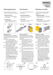
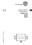
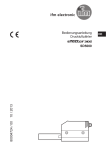
1
Bedienungsanleitung
Operating instructions
Notice pour utilisateurs
R
Schaltverstärker VS 0200
Control monitor VS 0200
Boîtier électronique
VS 0200
1
2
3
Temp. / temp.
4
5
–
6
Strömung / flow
Relais /
relay
7
8
+
Relais /
relay
VS 0200
Temp. / temp.
40
60
20
80
°C
Strömung / flow
1
2
1 Flüssig /
liquid
2 Gas / gas
9
10
11
12
–
+
ifm electronic
D 45127 Essen
13 14 15 16
Bestimmungsgemäße Verwendung
Der Schaltverstärker VS 0200 ist konzipiert für
den Anschluß von Strömungssensoren. Er wertet die Signale der Sensoren aus und meldet,
ob ein voreingestellter Strömungswert erreicht
ist (= Medium strömt / Ausgangsrelais ist angezogen) oder nicht (=Medium strömt nicht /
Ausgangsrelais ist abgefallen).
• Wahlweise Überwachung flüssiger oder gasförmiger Strömungen.
• Zusatzoptionen:
Überwachung der Sensorleitung: Bei Leitungsbruch und Kurzschluß fällt das Überwachungsrelais ab, die rote LED leuchtet.
Temperaturüberwachung: Bei Überschreiten
der eingestellten Temperatur zieht das Relais
an, die rote LED leuchtet.
Montage
Befestigen Sie das Gerät auf einer 35mmProfilschiene oder durch Schrauben auf einer
Montagevorrichtung. Setzen Sie die EURO-Karte
in einen 19"-Baugruppenträger ein.
Elektrischer Anschluß
Schalten Sie die Anlage spannungsfrei
und schließen Sie das Gerät an.
Um Funktionsbeeinträchtigungen durch Störspannungen zu vermeiden, sollten Sensorkabel
und Lastkabel getrennt voneinander verlegt
werden. Maximale Länge des Sensorkabels:
100m.
d b z
2
4
6
8
10
12
14
16
18
20
22
24
26
28
30
32
Sensor 1
WH
z2
z18
BU
z4
b20 R1 (K1)
BN
z6
b18
BK
z8
z22
GY z10
z12/b12
z14/b14
Sensor 2
Adernfarben:
BN = braun, BU = blau, BK = schwarz, WH =
weiß, GY = grau
R1 = Relais Strömungsüberwachung
R2 = Relais Leitungsüberwachung oder
Temperaturüberwachung
(K1) = Meßkreis 1
(K2) = Meßkreis 2
b24 R2 (K1)
b22
z26
WH
b2
b28 R1 (K2)
2 WH
BU
b4
b26
3 BU
BN
b6
z30
1 BN
BK
b8
b32 R2 (K2)
4 BK
GY
b10
b30
5 GY
1
2
3
4
5
6
7
8
9
10 R2
11
12
13 R1
14
15 L1/L+
16 N/L-
Einstellen
5
1
2 (K1)
3
4
(K1)
(K2)
1
2
3
1
2
3
Temp. / temp.
5
6
Strömung / flow
Relais /
relay
7
8
+
Relais /
relay
VS 0200
Temp. / temp.
1
2 (K2)
3
4
4
–
Strömung / flow
60
40
80
20
°C
1
2
1 Flüssig /
liquid
2 Gas / gas
9
4
10
11
12
–
+
ifm electronic
D 45127 Essen
13 14 15 16
5
(K1) = Meßkreis 1
(K2) = Meßkreis 2
1 = LED-Kette
- rote LED leuchtet: Gerät ist nicht
abgeglichen
- gelbe LED leuchtet: Relais ist
angezogen
- grüne LED leuchtet: Gerät ist
abgeglichen
2 = Einstellpotentiometer:
Empfindlichkeit
3 = LED rot
- leuchtet bei Leitungsbruch oder Kurzschluß
- leuchtet bei Temperaturüberschreitung
4 = Poti Temperaturüberwachung
5 = Wahlschalter Medium
flüssig
gasförmig
flüssig
gasförmig
Betrieb: Der Betrieb des VS 0200 ist wartungsfrei.
Bei Leitungsbruch oder Kurzschluß fällt das
Relais “Leitungsüberwachung” ab und die rote
LED leuchtet. Nach Behebung der Störung ist
der Schaltverstärker wieder betriebsbereit.
1. Stellen Sie den Wahlschalter (5) auf flüssige
oder gasförmige Medien ein.
2. Schalten Sie die Betriebsspannung ein.
Schalten Sie die Strömung ein (Sollwert) und
halten Sie sie konstant.
→ Für ca. 30s leuchten die gelbe und eine
grüne LED; das Ausgangsrelais ist angezogen (Bereitschaftsverzögerungszeit).
3. Drehen Sie das Einstellpotentiometer (2), bis
eine grüne LED leuchtet.
Je weiter die grün aufleuchtende LED von
der gelben LED entfernt ist, desto sicherer ist
der Abgleich (Betriebsreserve für Strömungs- oder Temperaturschwankungen).
Functions and features
The control monitor VS 0200 is designed to work
with flow sensors. The control monitor evaluates
the signals from the sensors and senses whether
there is a preset flow rate (= medium flowing /
output relay energised) or not (= medium not
flowing / output relay de-energised).
• Flows of either liquids or gases can be monitored.
• Options:
Wire break monitoring: in the case of an
open-circuit or short-circuit the monitoring
relay is de-energised, the red LED signals a
fault.
Temperature monitoring: relay is energised
when temperature is exceeded, the red LED
signals a fault.
Installation
Mount the housing on a 35mm DIN rail or
attach it to a mounting plate. Insert the EURO
card into a 19" rack.
Electrical connection
Isolate power supply before connecting
the unit.
Core colours: BN = brown, BU = blue, BK =
black, WH = white, GY = gray
In order to avoid malfunction caused by interference, lay the sensor cable separately from
the load cable. Max. length of the sensor cable:
100m.
R1 = relay “flow monitoring”
R2 = relay “wire monitoring” or “temperature
monitoring”
(K1) = measuring circuit 1
(K2) = measuring circuit 2
d b z
2
sensor 1
4
6
8
10
12
14
16
18
20
22
24 sensor 2
26
28
30
32
WH
z2
z18
BU
z4
b20 R1 (K1)
BN
z6
b18
BK
z8
z22
GY z10
z12/b12
z14/b14
b24 R2 (K1)
b22
z26
WH
b2
b28 R1 (K2)
2 WH
BU
b4
b26
3 BU
BN
b6
z30
1 BN
BK
b8
b32 R2 (K2)
4 BK
GY
b10
b30
5 GY
1
2
3
4
5
6
7
8
9
10 R2
11
12
13 R1
14
15 L1/L+
16 N/L-
Adjustment
5
1
2 (K1)
3
4
(K1)
(K2)
1
2
3
1
2
3
Temp. / temp.
5
6
Strömung / flow
Relais /
relay
7
8
+
Relais /
relay
VS 0200
Temp. / temp.
1
2 (K2)
3
4
4
–
Strömung / flow
60
40
80
20
°C
1
2
1 Flüssig /
liquid
2 Gas / gas
9
4
10
11
12
–
+
ifm electronic
D 45127 Essen
13 14 15 16
5
(K1) = measuring circuit 1
(K2) = measuring circuit 2
1 = hain of LED’s
- red LED lights: the unit is not
adjusted
- yellow LED lights: the relay is
energised
- green LED lights: the unit is adjusted
2 = setting potentiometer
sensitivity
3 = red LED
- lights in case of wire break or short circuit
- lights in case of temperature exceeding
4 = potentiometer temperature monitoring
5 = slide switch (medium)
liquids
gases
1. Set the selector switch (5) to liquids or gases
2. Apply the operating voltage. Switch on the
flow (preset value) and keep it constant.
→ The yellow LED and one green LED light;
the output relay is energised for about 30 s
(power-on delay time).
3.Turn the pot (2) until one green LED comes
on.
The farther the green LED is away from the
yellow LED, the safer is the adjustment (excess gain for flow or temperature fluctuations).
liquids
gases
Operation: The operation of the VS0200 is
maintenance-free.
In the case of an open circuit or short circuit the
relay “wire monitoring” is de-energised and
the red LED is lit. When this fault has been
rectified, the control monitor is again ready for
operation.
Fonctionnement et caracéristiques
Le VS 0200 est prévu pour le raccordement des
détecteurs de circulation de fluides. Il évalue les
signaux des sondes et indique si une valeur de
circulation présélectionnée est atteinte (= liquide
en circulation / relais de sortie enclenché) ou
non (liquide pas en circulation / relais de sortie
déclenché).
• Surveillance des circulations soit liquides soit
gazeuses au choix.
• Options
Fonction surveillance du câble de la sonde:
dans le cas d’une rupture de câble et de
court-circuit le relais de surveillance déclenche,
la LED rouge indique la présence d’un défaut.
Fonction surveillance de la température: le
relay est enclenché si la température est trop
élevée, la LED rouge indique la présence d’un
défaut.
Montage
Monter le boîtier électronique sur un profilé 35 mm
ou le visser sur un dispositif de montage. Insérer
la carte EURO dans un support 19".
Raccordement électrique
Mettre l’installation hors tension avant le
raccordement de l’appareil.
Afin d’éviter un dysfonctionnement causé par
des tensions parasites nous recommandons
d’installer le câble de la sonde séparément du
câble de la charge. Longueur maximale du
câble de la sonde: 100 m.
d b z
2
4
6
8
10
12
14
16
18
20
22
24
26
28
30
32
sonde 1
WH
z2
z18
BU
z4
b20 R1 (K1)
BN
z6
b18
BK
z8
z22
GY z10
z12/b12
z14/b14
sonde 2
Couleurs des fils: BN = brun, BU = bleu, BK =
noir, WH = blanc, GY = gris
R1 = relais «contrôle de circulation»
R2 = relais «surveillance du câble» ou
«surveillance de la température»
(K1) = circuit de mesure 1
(K2) = circuit de mesure 2
b24 R2 (K1)
b22
z26
WH
b2
b28 R1 (K2)
2 WH
BU
b4
b26
3 BU
BN
b6
z30
1 BN
BK
b8
b32 R2 (K2)
4 BK
GY
b10
b30
5 GY
1
2
3
4
5
6
7
8
9
10 R2
11
12
13 R1
14
15 L1/L+
16 N/L-
Réglage
5
1
2 (K1)
3
4
(K1)
(K2)
1
2
3
1
2
3
Temp. / temp.
5
6
Strömung / flow
Relais /
relay
7
8
+
Relais /
relay
VS 0200
Temp. / temp.
1
2 (K2)
3
4
4
–
Strömung / flow
60
40
80
20
°C
1
2
1 Flüssig /
liquid
2 Gas / gas
9
4
10
11
12
–
+
ifm electronic
D 45127 Essen
13 14 15 16
5
(K1) = circuit de mesure 1
(K2) = circuit de mesure 2
1 = rampe de LED
- la LED rouge est allumée: l’appareil
n’est pas réglé
- la LED jaune est allumée: la relais
est enclenché
- la LED verte est allumée: l’appareil
est réglé
2 = potentiomètre de reglage
sensibilité
3 = LED rouge
- est allumée en cas de rupture
- est allumée si la température est trop élevée
4 = potentiomètre (contrôle de la température)
5 = commutateur (sélection du fluide)
liquide
gazeux
liquide
gazeux
Fonctionnement: Le fonctionnement du
VS0200 ne nécessite aucun entretien.
En cas de rupture de câble ou de court-circuit
le relais «surveillance du câble» est déclenché
et la LED rouge est allumée. Après rectification
du défaut le boîtier électronique est de nouveau opérationnel.
1. Sélectionner milieux liquide ou gazeux à
l’aide du sélecteur.
2. Mettre l’appareil sous tension. Mettre en
débit constant (valeur présélectionnée).
→ La LED jaune et une LED verte sont allumées
et le relais de sortie est enclenché durant env.
30s (retard à la disponibilité).
3. Tourner le potentiomètre jusqu’à ce qu'une
LED verte soit allumée.
Plus la LED verte allumée est éloignée de la
LED jaune, plus sûr est le réglage (capacité
de réserve en cas de fluctuations de débit ou
de température).
Sachnr. 701151/05
10/97