1
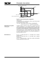
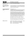
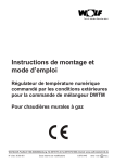
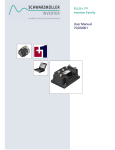
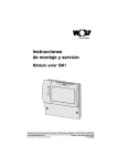
Installation and
operating instructions
Mixer module MM
Wolf GmbH · Postfach 1380 · D-84048 Mainburg · Tel. +49-8751/74-0 · Fax +49-8751/741600 · Internet: www.wolf-heiztechnik.de
3061892_0111Subject to modifications
GB
Index
Safety instructions.............................................................................3
Standards / Regulations....................................................................4
Terminology.......................................................................................5
Abbreviations / Equipment description..............................................6
Installation.........................................................................................7
Electrical connection................................................................... 8-22
Config. 1:
Mixer circuit and cylinder circuit........................... 12
Config. 2:
Mixer circuit and air heater circuit........................ 13
Config. 3:
Mixer circuit and heating circuit............................ 14
Config. 4:
Mixer circuit and return temperature
raising for heating backup.................................... 15
Config. 5:
Return temperature raising for soft starting.......... 16
Config. 6:
Heating circuit and return temperature raising for soft starting with bypass pump............ 17
Config. 7:
Mixer circuit with indirect return temperature
raising for soft starting with bypass pump............ 18
Config. 8:
Mixer circuit (factory setting)................................ 19
Config. 9:
Heating circuit...................................................... 20
Config. 10: Cylinder circuit...................................................... 21
Config. 11: Air heater circuit................................................... 22
Commissioning ............................................................................. 23
Setting the eBUS address.......................................................... 24-26
Switching times ............................................................................. 27
Parameter list
........................................................................ 28-30
Parameter description................................................................ 31-36
2
01 Minimum mixer circuit temperature.................................... 31
02 Maximum mixer circuit temperature................................... 31
03 Heating curve gap.............................................................. 31
04 Screed drying..................................................................... 31
05 Configuration..................................................................... 32
06 Pump run-on time, heating circuit...................................... 32
07 Proportional range, mixer circuit........................................ 32
08 Set return temperature....................................................... 33
09 Maximum cylinder heating time......................................... 34
10 BUS feed........................................................................... 34
11 Hysteresis, bypass sensor................................................. 35
12 Primary pump, blocking..................................................... 35
13 Primary pump, run-on time................................................ 35
14 Constant temperature........................................................ 35
3061892_0111
Index / Safety instructions
15
∆TOff (shutdown differential)............................................. 35
16
∆TOn (start-up differential)................................................. 36
17 Boiler excess temperature
during DHW cylinder heating............................................. 36
18
Burner blocked when the
return temperature is raised............................................... 36
50 Test function....................................................................... 36
Auxiliary functions........................................................................... 37
Cylinder frost protection............................................................ 37
Anti-seizing pump protection.................................................... 37
Anti-seizing mixer protection..................................................... 37
Emissions test........................................................................... 37
Loading the standard values.................................................... 37
Fault codes
............................................................................. 38
Changing a fuse............................................................................. 39
Sensor resistances.......................................................................... 40
System example, injection control.............................................. 41-43
Specification
Safety instructions ............................................................................. 44
The following symbols are used in conjunction with these important
instructions concerning personal safety as well as operational
reliability.
"Safety instructions" are instructions with which you must comply
exactly, to prevent injury and material losses.
Danger through 'live' electrical components.
NB Switch OFF the ON / OFF switch before removing the casing.
Never touch electrical components or contacts when the ON / OFF
switch is in the ON position. This brings a risk of electrocution,
which may result in injury or death.
The main supply terminals are 'live' even when the ON / OFF
switch is in the OFF position.
Attention
3061892_0111
This indicates technical instructions which you must observe to
prevent material losses and boiler malfunctions.
3
Standards / Regulations
Standards and regulations
The boiler and control accessories comply with the following
regulations:
EG Directives
- 2006/95/EG
Low Voltage Directive
- 2004/108/EG
EMC Directive
EN Standards
- EN 60730-1
- EN 55014-2
- EN 60529
Installation /
Commissioning
- According to DIN EN 50110-1, only qualified electricians may
carry out the installation and commissioning of the heating control
unit and connected accessories.
- Observe all regulations stipulated by your local power supply
utility and all VDE or local regulations.
- DIN VDE 0100 regulations regarding the installation of high
voltage systems up to 1000V
- DIN VDE 0105-100 operation of electrical systems
Warnings
- Never remove, bypass or disable safety and monitoring equipment.
- Only operate the system in perfect technical condition. Immediately remove / remedy any faults and damage that may impact
on safety.
- Always ensure that cold water is mixed in with hot water, when
the DHW temperature is set above 60 °C or when pasteurising
at a temperature in excess of 60 °C (risk of scalding).
Maintenance / Repair
- Regularly check the perfect function of all electrical equipment.
- Only qualified personnel may remove faults or repair damage.
- Only replace faulty components or equipment with original Wolf
spare parts.
- Always maintain prescribed electrical protection values
(see specification).
Attention
4
Any damage or loss resulting from technical modifications to Wolf
control units is excluded from our liability.
3061892_0111
Terminology
Terminology
Heating water temperature
The heating water temperature is the radiator flow temperature.
The higher the heating water temperature, the higher the heat
transfer to radiators.
Mixer circuit temperature
The mixer circuit temperature is the flow return temperature
downstream of the mixer, with which underfloor heating systems
are supplied.
Cylinder heating
Heating up the DHW cylinder.
DHW Quick Start
The heating water in the boiler will be held at a certain temperature
during summer mode, to be able to supply hot water as rapidly as
possible from the instantaneous water heater of combi boiler that
is equipped with the DHW Quick Start function. The DHW time
program switches this function on and off during summer mode.
Heating program
Subject to program selection, the heating time program switches
the boiler from heating to setback mode or from heating mode to
heating off and vice versa.
Domestic hot water program
In a gas fired combi boiler equipped with the DHW Quick Start
function, the DHW time program controls the DHW Quick Start
and, for boilers with a DHW cylinder, enables / disables the cylinder heating.
Winter mode
Central heating and DHW according to the heating and DHW
time program.
Summer mode
Central heating off, DHW according to the DHW time program.
Heating mode / Setback mode
In winter mode, two room temperatures can be selected: Standard
room temperature and setback temperature. In the later case the
temperature will be reduced to the setback temperature.
The heating program changes over between heating and setback
mode.
3061892_0111
5
Abbreviations / Equipment description
Abbreviations
BPF - Bypass sensor
MKF- Mixer circuit sensor
PF - Buffer sensor
PK - Floating contact as N/O
RLF Return sensor
SPF - Cylinder sensor
VF - Flow sensor
Equipment description
The mixer module (MM) contains a mixer circuit controller and the
control for a programmable output. The mixer circuit controller can
be used for the heating flow as well as for the heating return. The
programmable output either regulates a direct heating circuit, a
cylinder circuit, an air heater (= ext. heat demand), an electrical
valve for raising the return temperature (= central heating backup)
or the bypass pump in conjunction with the return temperature
raising. Subject to application, select the relevant combination
of the mixer circuit controller and the programmable output as
configuration. Parameters can be changed and fault codes as well
as sensor values can be displayed at the programming module
(BM) or at the interface module ISM1 with Comfort Soft. The MM
has an eBUS interface and can therefore be integrated into the
Wolf control system.
MKP
MM
SPLP
LP
BPP
3WUV
- Mixer circuit pump
- Mixer motor or
Mixer module
- Cyl. primary pump
- Primary pump
- Bypass pump
- Three-way diverter
valve
Mixer circuit pump
Mixer motor OPEN
Mixer motor CLOSE
Output A1
eBUS
Fault
6
3061892_0111
Installation
Mixer module installation
- Remove the mixer module from the packaging.
- Fit the mixer module directly to the wall.
- Connect an outside temperature sensor to the gas fired boiler.
- Install the outside temperature sensor at a north or north
eastern wall at a height of 2 - 2.5 m from the ground
(cable grommet pointing downwards).
- Wire up the MM mixer module in accordance with the installation
diagram.
Cable cross-section for 230 V min. 0.75 mm²; for 24 V min.
0.5 mm².
Note: Never route on-site cables / leads for outside temperature
and flow temperature sensors together with mains
cables.
Einstellung eBUS
Einstellung eBUS
10.5 cm
A1
A1
Adresse 0
Adresse 0
Adresse 1(Werkseinstellung)
Adresse 1(Werkseinstellung)
Adresse 2
Adresse 2
Adresse 3
Adresse 3
Adresse 4
Adresse 4
Adresse 5
Adresse 5
Adresse 6
Adresse 6
Adresse 7
Adresse 7
Fixing holes
12.5 cm
3061892_0111
7
Electrical connection
Output A1
a) Electrical valve
For wall mounted boilers with integral boiler pumps, an electrical
valve can be connected to output A1 in case of configuration 1,
2, 3, 9, 10 and 11, subject to the integral boiler pump matching
the hydraulic design.
b) Heating circuit / primary pump
For wall mounted boilers with low loss header and for boilers
with or without low loss header, connect a pump to output A1 in
case of configuration 1, 2, 3, 9, 10 and 11.
Maximum thermostat
If the maximum thermostat is connected to terminals 4, 5 or 6 of
the MM, only the mixer circuit pump will be switched off in case
of faults (the mixer will no longer close); the MKP LED stays on.
With the injection control, the bypass and gravity brake ensure that,
if there is a fault, no heating water enters the mixer circuit, even
through the pump of the wall mounted boiler. Where no hydraulic
injection system is used as described on pages 41-43, either
A) install an electrical valve (off in the zero volt state) upstream of
the mixer circuit pump, and connect it electrically in parallel to the
mixer circuit pump. Application for several mixer circuits.
In case of faults (mixer no longer closes), the electrical valve
prevents an overheating of the mixing circuit in conjunction with
a maximum thermostat; or
B) for gas fired condensing centres, connect the maximum thermostat to terminal E1 of the gas fired condensing centre. E1 must
then be programmed in accordance with the maximum thermostat
(see installation instructions). The gas fired condensing centre will
be blocked as soon as the maximum thermostat opens. Application
for one mixer circuit.
Without a maximum thermostat, extremely high temperatures may
occur in the underfloor heating circuit, should the MM develop a
fault. This can result in the floor developing cracks.
Outside temperature sensor
There are four options for integrating an outside temperature
sensor into a system:
a)Outside temperature sensor at the boiler at terminal AF,
Part no. 2792021
b)Outside temperature sensor at BM (address 0) in the wall
mounted base at terminal 5/6 Part no. 2792021
c)Radio clock module with outside temperature sensor
connected to the eBUS, Part no. 2792325
d)Wireless outside temperature sensor and wireless receiver
connected to the eBUS. Part no. 2744081 and 2744209
Recommended cables and
cable cross-sections:
H005VV 3 x 1.0 mm²
H005VV 3 x 0.75 mm²
H005VV 4 x 0.75 mm²
H005VV 3 x 0.75 mm²
H005VV 2 x 0.5 mm²
Note:
During service work, isolate the entire system from the power
supply, otherwise there will be a risk of electrocution.
8
Power supply cable
Mixer circuit pump, max. thermostat
Mixer motor
Max. thermostat, electr. valve
BUS cable
3061892_0111
Electrical connection
Configuration overview
Subject to the application of the MM, there are 11 different connection methods. Select the different versions with the configuration parameter (MI05). This is found at the second control level →
Contractor → Mixer.
Configuration 01: Mixer circuit and cylinder circuit; page 12
Configuration 02: Mixer circuit and air heater circuit, external heat demand; page 13
Configuration 03: Mixer circuit and heating circuit; page 14
Configuration 04: Mixer circuit and return temperature raising for heating backup; page 15
Configuration 05: Return temperature raising for soft starting; page 16;
Applies to single and multi boiler systems (cascade) in conjunction with
R1/R2/R3/R21 boiler control units.
In this configuration, the mixer module acts as return temperature
raising facility for one boiler. In multi boiler systems, return temperature
raising requires a separate mixer module for each boiler.
On single boiler systems without cascade module, set parameter HG06
pump operating mode to "1" (1 = feed pump). This is found at control
level 2 →Contractor →Boiler.
Every mixer module for return temperature raising with configuration 5
must be assigned to a boiler.
Assignment (↔) via addressing the boiler and mixer module MM:
a) for single boiler systems without cascade module R1/R2/R21 (address 0 = factory-set)↔MM (address 1 = factory-set)
R3 (address 0 = factory-set)↔MM (address 2)
b) for single and multi boiler systems with cascade module
Boiler 1: R1/R21 (address 1) ↔MM (address 2)
Boiler 2: R1/R21 (address 2) ↔MM (address 3)
Boiler 3: R1/R21 (address 3) ↔MM (address 4)
Boiler 4: R1/R21 (address 4) ↔MM (address 5)
Note: 3061892_0111
Additional mixer modules up to address 7 can be configured
individually.
System examples, see also Wolf hydraulic schemes for medium-sized
boilers.
9
Electrical connection
Configuration 06: Heating circuit and return temperature raising for soft starting with
bypass pump; page 17.
Applies to single boiler systems without cascade module in conjunction
with R1/R2/R3/R21 boiler control units
R1/R2/R21 (address 0 = factory-set)↔MM (address 1 = factory-set)
R3 (address 0 = factory-set.)↔MM (address 2)
Additional mixer modules up to address 7 can be configured
individually.
The mixer module with configuration 6 must be assigned to the boiler.
Assignment (↔) via addressing the mixer module MM:
Note:
System examples, see also Wolf hydraulic schemes for
medium-sized boilers.
Configuration 07: Mixer circuit with indirect return temperature raising for soft starting with
bypass pump; page 18.
Applies to single boiler systems in conjunction with R1/R2/R3/R21 boiler
control units.
In conjunction with a cascade module, configuration 07 must be set at the
cascade module. In that case, configuration 7 must not be assigned at the
mixer modules.
The mixer module with configuration 7 must be assigned to the boiler.
Assignment (↔) via addressing the mixer module MM:
R1/R2/R21 (address 0 = factory-set)↔MM (address 1 = factory-set)
R3 (address 0 = factory-set)↔MM (address 2)
Additional mixer modules up to address 7 can be configured individually.
Note:
System examples, see also Wolf hydraulic schemes for
medium-sized boilers.
10
3061892_0111
Electrical connection
Configuration 08: Mixer circuit (factory setting); page 19
Configuration 09: Heating circuit; page 20
Configuration 10: Cylinder circuit; page 21
Configuration 11: Air heater circuit, external heat demand; page 22
Notes:
Restart the system after every configuration change. (Mains "On"/
mains "Off")
Switch the mains power OFF and then ON again via the
emergency stop switch of the heating system or via an MCB.
3061892_0111
11
Electrical connection
Configuration 1: Mixer circuit and cylinder circuit
L1 N
L1
230 V~ 50Hz
Netz
Mains
3
L N
A Z N N
L1
MaxTH
MKP
3
3
MM
L1
A1
4
1
2
3
Cylinder
primary pump
SPLP1)
Power
230 VAC
J
2
2
Cylinder
sensor SP
1
2
VF
E2
J
10 A
L1 N PE
1
E1
+
-
2
-
2
J
Flow sensor; mixer
circuit VF
eBUS
M
Maximum
thermostat
max. TH
+
eBUS eBUS
Boiler
Gas fired
boiler
Mixer motor
MM
DHW
cylinder
Mixer circuit
pump MKP
Mixer motor
MM
SPF
MaxTH
VF
MKP
MM
SPLP1)
M
Heating flow
Heating return
1)
Whether pump or electrical valve, see description "Output A1", page 8.
12
3061892_0111
Electrical connection
Configuration 2: Mixer circuit and air heater circuit / external heat demand
L1 N
L1
230 V~ 50Hz
Netz
Mains
3
L
N
A
L1
MaxTH
MKP
3
3
Z
N N
MM
L1
A1
4
1
2
1
3
2
E2
E1
2
1
2
VF
+
-
+
-
eBUS eBUS
2
2
J
10 A
L1 N PE
Primary
pump
LP1)
Power
230 VAC
J
Zero volt
contact
PK2)
(N/O)
Flow sensor; mixer
circuit VF
eBUS
M
Maximum
thermostat
max. TH
Boiler
Gas fired
boiler
Mixer motor
MM
Air heater
circuit
Mixer circuit
pump MKP
Mixer circuit
MaxTH
VF
MKP
MM
LP1)
M
Heating flow
Heating return
1)
2)
Whether pump or electrical valve, see description "Output A1", page 8.
Heat demand for air heater circuit / external heat demand.
3061892_0111
13
Electrical connection
Configuration 3: Mixer circuit and heating circuit
L1 N
L1
Mains
230 V~ 50Hz
Netz
3
L
N
A
L1
MaxTH
MKP
3
3
Z
N N
MM
L1
A1
4
1
2
E1
1
2
E2
3
1
2
VF
+
-
+
-
eBUS eBUS
2
2
J
10 A
Flow sensor; mixer
circuit VF
Heating
circuit pump
HKP1)
L1 N PE
Power
230 VAC
J
eBUS
M
Maximum
thermostat
max. TH
Boiler
Gas fired
boiler
Mixer motor
MM
Mixer circuit
pump MKP
Mixer circuit
Heating circuit
MaxTH
VF
MKP
MM
HKP1)
M
Heating flow
Heating return
1)
Whether pump or electrical valve, see description "Output A1", page 8.
14
3061892_0111
Electrical connection
Configuration 4: Mixer circuit and return temperature raising for heating backup
L1 N
L1
230 V~ 50Hz
Mains
Netz
3
L N
A Z N N
L1
MaxTH
MKP
3
3
MM
1
L1
A1
4
2
3
1
2
2
+
2
2
J
10 A
1
VF
E2
E1
+
-
-
eBUS eBUS
2
2
J
Flow senBuffer
sensor PF sor; mixer
circuit VF
L1 N PE
Power
230 VAC
Diverter valve
3 WUV
J
J
Return sensor RLF
M
Maximum
thermostat
max. TH
Boiler
Gas fired
boiler
Mixer motor
MM
Mixer circuit
pump MKP
eBUS
Mixer circuit
MaxTH
VF
Buffer
MKP
MM
M
RLF
PF
Heating flow
AB
Heating return
B
A
3WUV
3061892_0111
15
Electrical connection
Configuration 5: Return temperature raising for soft starting
L1 Mains
N
230 V~ 50Hz
Netz
L1
L
MaxTH
N
L1
MKP
A
Z
N N
MM
3
1
L1
A1
2
E1
4
1
2
E2
1
2
VF
+
-
+
-
eBUS eBUS
2
2
J
10 A
Return
sensor RLF
L1 N PE
Power
230 VAC
eBUS
M
Boiler
Gas fired
boiler
Mixer motor
MM
Supplement heating and DHW
circuits with additional mixer
modules
Heating flow
RLF
Heating return
1)
ZUP
M
MM
1)
Connect the feed pump (ZUP) to the boiler control unit (at slot KKP).
16
3061892_0111
Electrical connection
Configuration 6: Heating circuit and return temperature raising for soft starting with
bypass pump
L1 N
L1
230 V~ 50Hz
Mains
Netz
L N
MaxTH
L1
MKP
A Z N N
MM
3
1
L1
A1
4
1
2
1
2
3
2
VF
E2
E1
2
+
-
+
-
eBUS eBUS
2
2
J
10 A
Return
sensor
RLF
Bypass pump
BPP
L1 N PE
Power
230 VAC
J
Bypass
sensor BPF
M
eBUS
Boiler
Gas fired
boiler
Mixer motor
MM
Heating circuit
HKP
1)
MM
M
Heating flow
RLF
BPP
BPF
Heating return
1)
Connect the heating circuit pump (HKP) to the boiler control unit.
3061892_0111
17
Electrical connection
Configuration 7: Mixer circuit with indirect return temperature raising for soft
starting with bypass pump
L1 N
L1
230 V~ 50Hz
Mains
Netz
3
L N
A Z N N
L1
MaxTH
MKP
3
3
MM
L1
A1
4
1
2
1
3
2
2
2
J
10 A
L1 N PE
Bypass pump
BPP
Power
230 VAC
1
2
VF
E2
E1
+
-
+
-
eBUS eBUS
2
2
J
Bypass
sensor BPF
Flow sensor, mixer
circuit
V
J
J
Return sensor RLF
M
Maximum
thermostat
max. TH
eBUS
Boiler
Gas fired
boiler
Mixer motor
MM
Mixer circuit
pump MKP
Mixer circuit
MaxTH
VF
MKP
MM
M
Heating flow
RLF
BPP
BPF
Heating return
18
3061892_0111
Electrical connection
Configuration 8: Mixer circuit (factory setting)
L1 N
L1
230 V~ 50Hz
MNetz
ains
3
L N
A Z N N
L1
MaxTH
MKP
3
3
MM
L1
A1
1
2
1
2
E2
E1
4
1
2
VF
+
-
+
-
eBUS eBUS
2
2
J
10 A
Flow
sensor,
mixer
circuit
VF
L1 N PE
Power
230 VAC
J
eBUS
M
Maximum
thermostat
max. TH
Boiler
Gas fired
boiler
Mixer motor
MM
Mixer circuit
pump MKP
Mixer circuit
MaxTH
VF
MKP
MM
M
Heating flow
Heating return
3061892_0111
19
Electrical connection
Configuration 9: Heating circuit
L1 N
L1
230 V~ 50Hz
Mains
Netz
L N
MaxTH
3
L1
MKP
A Z N N
MM
L1
A1
1
1
2
2
E2
E1
1
2
VF
+
-
+
-
eBUS eBUS
3
2
10 A
L1 N PE
Power
230 VAC
Heating circuit
pump HKP1)
eBUS
Boiler
Gas fired
boiler
Heating circuit
HKP
1)
Heating flow
Heating return
1)
Whether pump or electrical valve, see description "Output A1", page 8.
20
3061892_0111
Electrical connection
Configuration 10: Cylinder circuit
L1 N
L1
230 V~ 50Hz
Mains
Netz
L N
MaxTH
3
L1
MKP
A Z N N
MM
L1
A1
1
2
3
1
2
E2
E1
1
2
VF
+
-
+
-
eBUS eBUS
2
2
J
10 A
L1 N PE
Power
230 VAC
Cylinder primary
pump SPLP1)
Cylinder sensor
SPF
eBUS
Boiler
Gas fired
boiler
DHW
cylinder
SPF
SPLP1)
Heating flow
Heating return
1)
Whether pump or electrical valve, see description "Output A1", page 8.
3061892_0111
21
Electrical connection
Configuration 11: Air heater circuit / external heat demand
L1 N
L1
230 V~ 50Hz
Mains
Netz
L N
MaxTH
3
L1
MKP
A Z N N
MM
L1
A1
1
2
3
1
2
E2
E1
1
2
VF
+
+
-
-
eBUS eBUS
2
2
10 A
L1 N PE
Power
230 VAC
Primary
pump LP1)
Zero volt
contact PK2)
(N/O)
eBUS
Boiler
Gas
fired
boiler
Air heater circuit
LP1)
Heating flow
Heating return
1)
2)
Whether pump or electrical valve, see description "Output A1" page 8.
Heat demand for air heater circuit (external heat demand).
22
3061892_0111
Commissioning
Commissioning guidelines
Implement the following steps in the order in which they are listed to achieve successful commissioning with regards to addressing and programming all control components and the system
configuration.
Note: Step 1
Step 2
Step 3
Step 4
Step 5
Step 6
Step 7
HG, KM, MM and SOL parameters are found at control level 2 → Contractor
→Boiler (HG) / Cascade (KM) / Mixer (MM) / Solar (SOL) in the programming
module (BM). If a cascade module is installed in the system, use the
commissioning guidelines from the installation and operating instructions of the
cascade module.
e
e
e
e
Implement the "Installation" and "Electrical connection" of all extension
and programming modules in accordance with the instructions in the
associated manual.
For further details regarding the setting of the eBUS address (DIP
switches) of the extension and programming modules (MM and BM),
see "Setting the eBUS address - extension modules".
Start the system via the system On/Off switch (mains "On").
Configuration of the extension modules just like mixer module and solar
module.
The configuration of the MM mixer module and SM2 solar module is made
in parameter MI 05 (= mixer module configuration) and parameter SOL12
(= solar module configuration) in accordance with the hydraulic scheme.
See "Electrical connection" in the mixer module or solar module installation
instructions regarding the selection of the correct configuration.
Programming the Wolf boiler control unit.
When selecting configuration 5 at the mixer module, select pump operating
mode 1 at the R1/R2/R3/R21 boiler control unit. → HG06 = 1.
e
e
e
Note: 3061892_0111
Programming the following components
1. In BM programming module, set parameters, such as time, day,
time programs etc.
2. Adjust MM and SM extension module parameters according to
requirements.
Restart the system by means of the system On/Off switch (switch the
mains OFF and then ON again). The system is ready for operation after
approx. 1 min.
If mixers 2-7 are operated / programmed by the BM (o), the status display of the
BM will show the "Sun" and "Moon" symbols simultaneously, as soon as one of
the mixers calls for heat.
23
Setting the eBUS-Address of the extension
and programming modules (MM, BM)
Setting the eBUS-Address
of the extension and
programming modules
(MM, BM)
Settings eBUS
Address 0
Address 1 (factory setting)
Address 2
Address 3
Address 4
Address 5
Address 6
Address 7
ON
DIP
1 2 3 4
Dip 1-4
ON
OFF
Subject to the installed Wolf boiler, up to seven mixer modules
per system can be connected. The MM addresses are assigned
in sequence from 1 to 7 in conjunction with the Wolf control unit
for wall mounted boilers, MGK or the Wolf boiler control units R1/
R2/R21/COB. In conjunction with the Wolf control unit R3, the
addresses of the MM are allocated from 2 to 7.
The functions of each mixer module are determined via the configuration settings (see also electrical connection).
Each system can comprise up to seven mixer circuits and one
direct heating circuit.
This direct heating circuit can either be connected to the boiler
control unit (R1/R2/R3/R21/COB) or the mixer module (config. 3
or 9). On systems with KM cascade module, the direct heating
circuit must be connected to the KM or MM.
In addition, each mixer module (mixer circuit) may be supplemented
with a BM programming module to complete the control. The
heating circuit is always controlled by the programming module
with address 0.
a) Max. expansion with Wolf boiler control unit for wall mounted
appliances, MGK control unit or Wolf boiler control units R1/
R2/R21/COB
HK*
MK 1
Wolf boiler
BM
MM 1
ON
ON
OFF
OFF
BM
ON
OFF
option
MK 2
MM 2
ON
MM 3
BM
ON
ON
OFF
OFF
OFF
ON
OFF
ON
OFF
ON
OFF
MM 4
option
MM 5
MM 6
MK 7
MM 7
ON
OFF
BM
ON
OFF
option
*In conjunction with a control unit for Wolf wall mounted boilers or MGK control unit, always connect
the direct heating circuit to the MM mixer module.
In conjunction with a Wolf boiler control unit R1/R2/R21/COB, the direct heating circuit can be
installed either directly on the boiler or on a mixer module. The factory setting provides for the
installation of the heating circuit on the boiler. If the direct heating circuit is connected to the mixer
module, set Pump operating mode parameter HG06 to "1" (1 = feed pump). This is found at the
second control level → Contractor → Boiler.
24
3061892_0111
Setting the eBUS-Address of the extension
and programming modules (MM, BM)
b)Max. expansion with Wolf boiler control unit R3
HK*
MK 1
MK 2
Wolf boiler
BM
MM 1
ON
ON
OFF
OFF
BM
ON
OFF
option
BM
MK 3
ON
OFF
option
for MK1
ON
MM 3
MM 2
BM
ON
ON
OFF
OFF
OFF
ON
OFF
ON
OFF
MM 4
option
MM 5
MK 7
MM 6
ON
OFF
BM
ON
OFF
option
*In conjunction with a Wolf boiler control unit R3, the direct heating circuit can either be installed
directly on the boiler or on a mixer module. The factory setting provides for the installation of the
heating circuit on the boiler. If the direct heating circuit is connected to the mixer module, set Pump
operating mode parameter HG06 to "1" (1 = feed pump). This is found at the second control level
→ Contractor → Boiler.
3061892_0111
25
Setting the eBUS-Address of the extension
and programming modules (MM, BM)
Commissioning and setting
of the eBUS-Address of the
extension and programming
modules (BM, MM)
c) Max. expansion without Wolf boiler control unit or MGK standard
control unit
The MM can also be used as a stand-alone mixer circuit controller, if no boiler with eBUS interface is installed. The MM can also
be used as stand-alone mixer circuit controller, if no boiler with
interface is installed. In that case, connect an outside temperature
sensor to the BM (0) or a DCF receiver with outside temperature
sensor to the eBUS. System examples, see "Setting an eBUS
interface with Wolf boilers", point a).
Configurations 5, 6 and 7 may not be set without a Wolf boiler
being installed.
26
3061892_0111
Switching times
Setting parameters
The standard setting for all parameters and switching times
are fixed and stored in a non-volatile memory. All changes are
permanently stored and will not be lost, even if the power fails
for several weeks.
Parameters are set / modified via the BM programming module.
Check the description of operation and setting / modifying parameters in the BM installation and operating instructions.
Switching times
Mixer circuit: The switching times for the mixer are stored in the
respective mixer module.
This is found at the second control level → Time program →
Heating → Mixer.
Heating circuit and cylinder: The switching times for the heating
circuit and cylinder are stored in the BM programming module.
Time
program
Block
Switching
time
Time
prog. 1
Mo-Su
1
Mixer
ON
OFF
5:00
21:00
2
Program
Time
prog. 3
Block
Switching
time
Mo
1
1
22:00
Tu
5:00
7:00
2
14:00
21:00
6:00
21:00
1
4:30
20:00
4:30
20:00
4:30
20:00
4:30
20:00
4:30
20:00
4:30
20:00
3
1
We
1
2
3
Sa-Su
1
2
3
Mo-Fr
OFF
20:00
3
6:00
2
Time
prog. 2
ON
4:30
2
3
Sa-Su
Mixer
3
Th
2
1
2
3
3
Fr
1
2
3
Sa
1
2
3
Vu
1
2
3
3061892_0111
27
Parameter list
Parameter list
Standard setting
Parameters
This is found at the second control level → Standard setting →
Mixer.
Setting range
Factory setting
Standard temp
5 °C - 30 °C
20 °C
RED TEMP
5 °C - 30 °C
12 °C
GRADIENT
0-3
0.8
OFF - ON
OFF
0 °C - 40 °C
20 °C
-10 °C - 40 °C
10 °C
ROOM INFLU
W/S SWITCH
ECO-RED
Individual setting
Check the BM installation and operating instructions for a description of the parameters standard temperature, reduced temperature,
gradient, room influence, W/S changeover and ECO / RED.
Parameter list
Contractor system
System parameters A09, A10, A12 and A14 can only be set in the
programming module with address 0; all other system parameters
can be found in the associated programming modules.
These are found at the second control level → Contractor →
System.
Parameters
A00
Room influence
Setting
range
Factory setting
1 - 20
4
2
A09
Frost protection limit
-20 - 10
A10
Parallel pump mode
0-1
0
A11
Pump stop with room controller
off - on
on
A12
Setback stop
-40 - 0
16
A14
Maximum DHW temperature
60 - 80
60
Individual
setting
Check the description of the parameters room influence, frost
protection limit, pump stop with room controller, setback stop and
maximum DHW temperature in the BM installation and operating
instructions.
A10: Parallel pump operation
Parameter A10 = 0: Priority mode
Priority mode for cylinder heating (at the
mixer module) or primary pump for external
heat demand ahead of a heat demand for
the mixer output.
Parameter A10 = 1: Parallel operation
Parallel mode for cylinder heating (at the
mixer module) or external heat demand
with a heat demand for the mixer output.
Note:
28
In parallel mode, the highest possible flow
temperature is applied.
3061892_0111
Parameter list
Parameter list,
contractor, boiler
This is found at control level 2 → Contractor → Boiler.
Note:
Parameters HG08 and HG22 do not need to be changed for
those heating and cylinder circuits, for which the corresponding
parameters for calculating the set flow temperature are left at
their factory setting (e.g. set cylinder temperature). Parameters
HG08 and HG22 will need to be modified, if the factory settings
for heating and cylinder circuits are changed or if configurations
2 or 11 have been selected at the mixer module. For this, HG22
only needs to be changed in conjunction with the R1/R2/R3/R21
or COB boiler control unit.
HG08 settings:
a) Cylinder heating at the mixer module
HG08 ≥ set cylinder temperature + MI17 + HG01
b) External heat demand (convector heater) at the mixer module (configuration 2 or 11)
HG08 ≥ MI14 + HG01
b) Heating circuits (boiler or mixer module)
HG08 ≥ MI02 + MI03 + HG01
To safeguard the required flow temperatures for cylinder and
central heating (at the mixer module), set parameters HG08
(= maximum limit, boiler circuit TV-max.) and HG22 (= maximum boiler water temperature TK-max) to the highest required
temperature level.
HG22 settings:
HG22 ≥ HG08
Parameter list
HG01
Burner switching differential
HG08
Maximum limit, boiler circuit TV-max
HG22
Maximum boiler limit TK-max
3061892_0111
Parameters, individual
settings
29
30
0 °C – 80 °C
20 °C – 80 °C
0 K – 30 K
0 (Off) - 2
1 - 11
0 – 30min
5 K – 40 K
Min. mixer circuit temp
Max. mixer circuit temp
Heating curve gap
Screed drying
Configuration
Run-on time, heating circuit
P range, mixer
Set return temperature
Max. cylinder heating time
BUS feed (1 = On)
MI01
MI02
MI03
MI04
MI05
MI06
MI07
MI08
MI09
MI10
2 – 20 K
4 – 30 K
0 – 40 K
0 – 300s
-
Primary pump, run-on time
Constant temperature
∆TOff (shutdown differential)
∆TOn (start-up differential)
Boiler excess temp. during cylinder heating
Burner blocked during return temp. raising
Test function
Analogue input E1
Analogue input E2
Analogue input, flow sensor VF
MI13
MI14
MI15
MI16
MI17
MI18
MI50
MI70
MI71
MI72
1
0s
10 K
10 K
5 K
75 °C
3min
0
10 °C
2
2h
30 °C
12 K
5min
8
0
10 K
50 °C
0 °C
Factory
setting
-
-
x
x
2
x
x
x
x
2
-
-
x
x
3
x
x
x
x
3
-
-
x
x
4
x
x
x
x
-
x
x
-
5
-
-
-
-
-
x
x
-
6
-
-
-
-
-
x
x
x
7
x
x
x
x
-
-
x
x
8
x
x
x
x
Configuration MM
4
5
6
7
8
-
-
-
x
9
-
-
-
-
9
x
-
-
-
10
-
-
-
-
10
-
-
-
-
11
-
-
-
-
11
x
-
x
-
-
-
x
x
-
x
-
-
-
-
x
x
x
-
x
-
--
-
-
-
x
-
-
x
-
-
x
x
-
-
-
-
x
-
-
-
-
-
-
-
-
x
-
-
-
-
-
-
-
x
x
-
-
-
-
-
-
-
x
x
-
-
-
-
-
-
-
-
x
-
-
-
-
-
-
-
-
x
-
x
-
-
-
x
x
-
x
-
-
-
-
x
x
x
-
X1) X1) X1) X1) X1) X1) X1) X1) X1) X1) X1)
x
-
x
x
1
x
x
x
x
1
Subject to the configuration of the mixer module, only specific parameters are effective and able to be adjusted as an option.
"X" =
optionally adjustable
"-" =
not active
never change the factory setting
"X1)" =
-
-
Display of the input sensor values
-
1-8
50 °C – 80 °C
0 - 10min
0-1
Primary pump blocking
0 °C – 30 °C
Hysteresis, bypass sensor
MI11
MI12
0 (Off) - 2 (Auto)
0 - 5h
20 °C – 80 °C
Setting range
Parameter
This is found at control level 2 → Contractor → Mixer
Parameter list, contractor, boiler
3061892_0111
Parameter description
MI 01 Minimum mixer
circuit temperature
This minimum mixer circuit temperature limits the low end of the
set mixer circuit flow temperature.
MI 02 Maximum mixer
circuit temperature
The maximum mixer circuit temperature limits the set flow temperature of the mixer circuit upwards, for example to prevent damage
to floor coverings. This does not, however, replace a maximum
thermostat for shutting down the pump.
MI 03 Heating curve gap
The heating water temperature will be raised by the set value
against the mixer circuit temperature.
MI 04 Screed drying
If an underfloor heating system is started for the first time in new
buildings, the set flow temperature may, as an option, be controlled independent of the outside temperature either to a constant
value or to control the set flow temperature in accordance with an
automatic screed drying program.
If this function has been enabled (setting 1 or 2), it can be terminated by resetting parameter MI 04 to 0.
MI 04 = 0 N / A
MI 04 = 1 constant temperature mixer circuit
The mixer circuit is heated to the set flow temperature. The set flow
temperature is regulated accurately to the temperature selected
in parameter MI 01.
MI 04 = 2 screed drying temperature
For the first two days, the set flow temperature will remain constant
at 25 °C. It will then be automatically raised every day (at 0:00
h) by 5 °C up to the maximum mixer circuit temperature (MI 02).
That temperature will then be held for two days. Subsequently,
the flow temperature is automatically reduced again in 5 °C steps
per day to 25 °C. The program sequence is terminated after a
further two days.
55
Fig.:
Flow temperature progress
over time during screed drying
Flow temperature (°C)
50
45
40
35
30
25
20
1
2
3
4
5
6
7
8
9 10 11 12 13 14 15 16 17
Screed drying runtime (days)
Attention
Agree the time sequence and the maximum flow temperature
with the screed contractor, otherwise the screed may be damaged, particularly through cracking. The screed drying program
continues after a power failure. The remaining time in days is
displayed at the BM.
3061892_0111
31
Parameter description
MI 05 Configuration
The corresponding configuration may, subject to the application of the MM, have to be selected. Up to 11 configurations
can be selected. For matching wiring diagrams, see "Electrical
connection".
Configuration 01: Mixer circuit and cylinder circuit
Configuration 02: Mixer circuit and air heater circuit /
external heat demand
Configuration 03: Mixer circuit and heating circuit
Configuration 04: Mixer circuit and return temperature raising
for heating backup
Configuration 05: Return temperature raising for soft starting
Configuration 06: Heating circuit and return temperature raising
for soft starting with bypass pump
Configuration 07: Mixer circuit with return temperature raising
for soft start with bypass pump
Configuration 08: Mixer circuit (factory setting)
Configuration 09: Heating circuit
Configuration 10: Cylinder circuit
Configuration 11: Air heater circuit / external heat demand
MI 06 Pump run-on time,
heating circuit
The mixer circuit pump / heating circuit pump will run on according
to the set value after the mixer circuit / heating circuit has been
switched OFF.
MI 07 Proportional
range, mixer circuit
Subject to application, the mixer circuit control can be configured for
the mixer circuit in the heating flow (configuration 1, 2, 3, 4, 7, 8) or
for the mixer circuit for return temperature raising (configuration 5, 6).
The mixer circuit temperature is regulated to the set value by means
of the mixer circuit sensor / return temperature sensor (mixer circuit
in the heating flow / mixer circuit for raising the return temperature)
via terminal VF and a motorised mixer. The output of the mixer
controller for regulating the mixer motor features P characteristics.
The P band can be changed for every parameter "P range
mixer".
The pulse duration (= activation of mixer motor) is directly
proportional to the mixer flow deviation (∆T = Set – Actual).
Parameter MI 07 determines the temperature deviation, for
which the pulse duration = 100%. Outside this range the mixer
is either not regulated at all (∆T < 1 K) or is regulated constantly
(∆T > setting of par. MI 07). Within the temperature range, the
system exerts constant control. Adjust the proportional range so
that stable regulation is ensured. This depends on the runtime of
the mixer motor. For mixer motors with a short runtime, select a
wide proportional range and vice versa for mixer motors with longer
runtimes, select a narrower proportional range.
Setting information: These settings are only approximate guidelines.
Change factory settings only where required.
Mixer runtime in min.
Temperature window in K (par. 27)
32
2-3
4-6
7-10
25-14
15-9
10-5
3061892_0111
Parameter description
MI 08 Set return
temperature
Mixer circuit for return temperature raising with
configuration MI 05 = 5 or 6
Configurations 5 and 6 include a mixer circuit control for return
temperature raising. Return temperature raising with configuration 5 is active, if the boiler assigned to the mixer module (assignment by addressing boiler and mixer module) is switched
by the cascade module (= burner "On"). The bypass is fully
opened at the end of the demand. With configuration 6, return
temperature raising is always active when at least one heating
or cylinder circuit is active. The bypass is fully opened when no
heating or cylinder circuit is active.
Return control:
If the actual return temperature falls below the set return temperature, then the mixer bypass is opened further by switching
the mixer, enabling a greater amount of heating water to flow
through the mixer bypass.
If the actual return temperature rises above the set return
temperature, then the mixer bypass is closed further by switching the mixer, restricting the amount of heating water to flow
through the mixer bypass.
Indirect return temperature raising with configuration
MI 05 = 7
Configuration 7 includes an indirect return temperature raising to
regulate the mixer circuit. The indirect return temperature raising
is always active when at least one heating or cylinder circuit is
active.
When the actual return temperature drops with indirect return
temperature raising, the actual return temperature is forced
higher for all heating and cylinder circuits through enforcing a
higher output. This forced higher output has two stages. At stage
1, all system mixers are switched to move towards "Close"; and,
in addition in stage 2, all heating and primary pumps at stage 1
are switched off.
Falling return temperature:
RL_act < RL_set + hysteresis, return temperature ⇒ mixer
towards CLOSE
RL_act < RL_set ⇒ mixer towards CLOSE and all heating circuit
pumps OFF
Rising return temperature:
RL_act > RL_set + 2 K ⇒ mixer towards CLOSE
RL_act < RL_set + hysteresis, return temperature + 4 K ⇒ no
forced actuation
Hysteresis, return temperature = 8 K
Example of a set return temperature = 30 °C:
Note:
3061892_0111
The set return temperature applies to configuration 5, 6
and 7.
33
Parameter description
Actual return temperature [K]
45
40
35
30
~
~
Time
Mixer CLOSE
Mixer CLOSE and pump OFF
Forced actuation
Bypass pump monitoring with configuration
MI 05 = 6 or 7
To monitor the return temperature, a timer is set (30 min) each
time the bypass pump is started.
Timer ON: RL_act ≤ RL_set for > 30 min ⇒ fault code 97
RL_act > RL_set + 2 K ⇒ reset timer and fault code
MI 09 Maximum cylinder
heating time
Cylinder heating is deemed to have been completed when the
cylinder temperature is ≥ set cylinder temperature. Fault code
52 is issued and the control unit switches over to heating mode
for the Max. cylinder heating time, if cylinder heating is not completed within the max. cylinder heating time (this does not apply
to the status heating = summer mode). This cycle continues until
the actual cylinder temperature is ≥ set cylinder temperature or
parameter MI09 is set to 0.
MI 10 BUS feed
MI 10 = 0: BUS feed OFF, i.e. the BUS feed is always
switched OFF.
MI 10 = 1: BUS feed ON, i.e. the BUS feed is always
switched ON.
MI 10 = 2: BUS feed Auto, i.e. the mixer module automatically
switches the BUS feed ON or OFF.
34
3061892_0111
Parameter description
MI 11 Hysteresis,
bypass sensor
With configuration 6 / 7, the programmable output A1 acts as
bypass pump in conjunction with a bypass sensor. One condition
for starting the bypass pump is, that at least one pump (pump
for heating circuit, cylinder or air heater) has been enabled in
the system.
Bypass pump ON: BPF_act < RL_set + hysteresis bypass sensor
Bypass pump OFF: BPF_act > RL_set + hysteresis bypass sensor + 5 K
MI 12 Primary pump,
blocking
For starting the primary pump, cylinder primary pump (configuration 1 and 10) or for ext. heat demand (configuration 2 and 11),
we differentiate between two cases:
a) Par. MI12 = 0: The primary pump is started immediately after
the command is issued.
b1) Par. MI12 = 1 with configuration 1 and 10:
Primary pump ON: Boiler flow temperature >
actual cylinder temperature + 5 K
Primary pump OFF: Boiler flow temperature ≤
actual cylinder temperature + 2 K
b2) Par. MI12 = 1 with configuration 2 and 11:
Primary pump ON: Boiler flow temperature ≥
constant temperature - 5 K
Primary pump OFF: Boiler flow temperature <
constant temperature - 8 K
If a cascade module is also installed in the system, instead of
the "Boiler flow temperature", the "Actual collector temperature"
is included in the determination whether the primary pump is
started or stopped.
Note:
The primary pump block must only be activated in the mixer module,
if at least one Wolf boiler or one cascade module is linked to the
mixer module via eBUS.
MI 13 Primary pump,
run-on time
The primary pump run-on starts after cylinder heating or ext. heat
demand has been terminated (configuration 1, 2, 10 and 11).
MI 14 Constant temperature
The system regulates to the selected set flow temperature,
and output A1 is regulated in case of an external heat demand
via a zero volt contact at input E1 and parameter configuration
= 2 or 11. External heat demand takes priority over any heat demand
from the heating circuits. The primary pump run-on starts after the
external heat demand has terminated. The program selector and
time channel heating or DHW have no influence.
MI 15 ∆TOff
(shutdown differential)
Configuration 4 comprises a mixer circuit control and a ∆T control
for central heating backup. A condition for central heating backup
is that, either a heating circuit demands heat or that the cylinder
heating / ext. heat demand is enabled. Otherwise central heating
backup is always OFF.
Output 1 ON, if PF_act > RL_act + ∆TOn
Output 1 OFF, if PF_act < RL_act + ∆TOff
3061892_0111
35
Parameter description
MI 16 ∆TOn
(start-up differential)
See "MI 15 ∆TOff (shutdown differential)"
MI 17 Boiler excess temperature during cylinder
heating
Cylinder heating starts when the actual cylinder temperature
< set cylinder temperature - 5 K. The set flow temperature then
results from the set cylinder temperature + excess boiler water
temperature during cylinder heating.
MI 18 Burner blocked when
the return temperature is
raised
Configuration Mm 01 = 4
For raising the return temperature during central heating backup,
a three-way diverter valve is controlled to raise the heating return
temperature via a buffer cylinder that has been heated up.
When the MM is operated as part of the Wolf WRS control system,
the boilers are blocked when the start conditions have been met.
If a demand is issued by at least 1 heating circuit or 1 cylinder, the
three-way diverter valve will be switched, and the blocking time set
in parameter MI 18 (= blocking time for burner blocking) starts. The
burner will be enabled again after the blocking time has expired.
The burner will be disabled for the set time when the start conditions have been met whilst the burner is already active.
Start conditions: PF_act (E1) > RLF_act (E2) + ∆TOn (MI 16)
Stop conditions: PF_act (E1) < RLF_act (E2) + ∆TOff (MI 15)
When setting a blocking time of 0 s (MI 18) the three-way diverter
valve will be controlled independently of any heat demand.
MI 50 Test function
36
Parameter MI50 enables the individual control of relays.
MI50 = 1 ⇒ Control of relay mixer circuit pump MKP
MI50 = 2 ⇒ Control of relay mixer motor OPEN MM
MI50 = 3 ⇒ Control of relay mixer motor CLOSE MM
MI50 = 4 ⇒ Control of relay output A1
3061892_0111
Auxiliary functions
Cylinder frost protection
The set cylinder temperature when cylinder heating is blocked
is 10 °C. Cylinder frost protection is activated when the actual
cylinder temperature < set cylinder temperature - 5 K. The set
flow temperature then results from the set cylinder temperature +
excess boiler water temperature during cylinder heating.
Anti-seizing pump
protection
To prevent the pumps from seizing because of long idle periods,
the mixer circuit pumps MKP and output A1 will be operated daily
for approximately five seconds (12:00 h at the mixer module) after
they have been idle for more than one day.
Anti-seizing mixer
protection
Subject to configuration (MI 05) = 1 / 2 / 3 / 4 / 7 / 8, the mixer
will be regulated to drive to OPEN for approx. 10 seconds daily
(12:00 h at the mixer module) and then for 20 seconds to CLOSE
to prevent the mixer from seizing up; if the configuration = 5 /
6, the mixer is driven for 10 seconds to CLOSE followed by 20
seconds to OPEN.
Emissions test
Emissions test enabled ⇒ Heating and DHW are enabled until
the emissions test has been completed.
Loading the standard values
Set DIP 4 to OFF and then back to ON. The standard values are
now loaded again. All LEDs illuminate briefly as confirmation.
3061892_0111
37
Fault codes
When MM recognises a fault, the red LED flashes and the mixer module fault code is displayed on
the associated BM as well as at the central BM (address 0). The following MM fault is transmitted
via the BUS and is displayed.
Faultcode
FC52
Fault
Cause
Remedy
Max. cylinder heating time
FC70
See parameter description MI09
Check sensor and lead,
replace, if required
Check sensor and lead,
replace, if required
FC97
Mixer circuit sensor or return
sensor fault (terminal VF)
Cylinder sensor, or buffer
sensor bypass sensor fault
(terminal E1)
Return sensor or bypass sensor faulty (terminal E2)
Bypass pump faulty
Max. cylinder heating
time exceeded
Faulty sensor or lead
FC81
EEPROM fault
FC91
BUS address
FC71
FC79
38
Faulty sensor or lead
Faulty sensor or lead
Bypass pump short
circuit
Faulty bypass pump
cable
Parameter values outside the valid range
Two or several accessory controllers have
the same BUS address
Check sensor and lead,
replace, if required
Check bypass pump,
check cable and connection replace, if required
Return to standard values
by briefly turning OFF,
and check values
Check address settings
3061892_0111
Changing a fuse
Changing a fuse:
If the MM indicates no function at all and there is no LED
display, although power is on, check the appliance fuse and
change it, if required.
Note:
If the MM is operated as part of the Wolf control system, the
display of one of the existing BM programming modules is retained, as this is supplied via the eBUS link to the other control
components.
Prior to opening the casing, isolate the mixer module from the
power supply.
Changing a fuse:
3061892_0111
1.
2.
3.
4.
Isolate the unit from the power supply
Remove the lid from the terminal chamber by
undoing both screws
Remove the casing top with a screwdriver
The fuse is located on the l.h. side of the PCB
below the transformer (fine-wire fuse 5x20/6.3A/M)
39
Sensor resistances
NTC Sensor resistances
Boiler sensor, cylinder sensor, solar cylinder sensor, outside
temperature sensor, flow sensor, central sensor
Temp.
Resist.
Temp.
Resist.
Temp.
Resist.
Temp.
Resist.
°C
Ohm
Ohm
Ohm
°C
Ohm
°C
Ohm
°C
-21
51393
14
8233
49
1870
84
552
-20
48487
15
7857
50
1800
85
535
-19
45762
16
7501
51
1733
86
519
-18
43207
17
7162
52
1669
87
503
-17
40810
18
6841
53
1608
88
487
-16
38560
19
6536
54
1549
89
472
-15
36447
20
6247
55
1493
90
458
-14
34463
21
5972
56
1438
91
444
-13
32599
22
5710
57
1387
92
431
-12
30846
23
5461
58
1337
93
418
-11
29198
24
5225
59
1289
94
406
-10
27648
25
5000
60
1244
95
393
-9
26189
26
4786
61
1200
96
382
-8
24816
27
4582
62
1158
97
371
-7
23523
28
4388
63
1117
98
360
-6
22305
29
4204
64
1078
99
349
-5
21157
30
4028
65
1041
100
339
-4
20075
31
3860
66
1005
101
330
-3
19054
32
3701
67
971
102
320
-2
18091
33
3549
68
938
103
311
-1
17183
34
3403
69
906
104
302
0
16325
35
3265
70
876
105
294
1
15515
36
3133
71
846
106
285
2
14750
37
3007
72
818
107
277
3
14027
38
2887
73
791
108
270
4
13344
39
2772
74
765
109
262
5
12697
40
2662
75
740
110
255
6
12086
41
2558
76
716
111
248
7
11508
42
2458
77
693
112
241
8
10961
43
2362
78
670
113
235
9
10442
44
2271
79
649
114
228
10
9952
45
2183
80
628
115
222
11
9487
46
2100
81
608
116
216
12
9046
47
2020
82
589
117
211
13
8629
48
1944
83
570
118
205
40
3061892_0111
System example, injection control
3061892_0111
41
System example, injection control
Key
UP Circulation pump (230 V AC min. 0.75 mm²)
Butterfly valve
Shut-off valve
M Mixer (230 V AC min. 0.75 mm²)
Gravity brake (opening pressure > 25 mbar)
Cap valve
TW Temperature controller for underfloor heating system (230 V AC)
VF Flow sensor
AF Outside temperature sensor
EV Electrical valve, N / C (230 V AC min. 0.75 mm²)
Direct connection of a mixer circuit via injection control
1.Applications
The injection control is used, if a mixer circuit with pump is to be directly connected (i.e. without
low loss header) to a gas fired boiler with integral pump. The injection control offers many benefits
compared to a conventional dual shunt pump control.
2.Description
The injection control includes an open bypass between flow and return in the mixer circuit, that
separates the mixer circuit pump from the boiler circuit.
The mixer equipped with a dummy plug controls the mass flow, that is injected into the mixer
circuit, subject to the flow temperature.
Benefits of injection control over shunt pump control:
- A hydraulic separation is created, thereby preventing the boiler pump and the mixer circuit pump
from affecting each other.
- The hydraulic balance is substantially easier to achieve, since every consumer circuit requires
only one butterfly valve.
- The pump capacity in the mixer circuit is reduced, because the mixer pressure drop must be added
to the boiler circuit.
- The mixer circuit pump will be switched OFF if, in an underfloor heating system, an excess temperature occurs in the mixer circuit. No additional solenoid valve – like those required for dual
shunt pump circuits – is required for interrupting the mixer circuit supply.
Installation requirements:
- Insert a dummy plug into the three-way mixer (see diagram).
- Size the mixer circuit pipework correctly.
Pump rate
up to 1720 l / h
∆T
Rated output
Internal diameter – pipework incl. bypass
10 K
up to 25 kW
DN 25
- Match up the mixer circuit and any existing consumer circuits with butterfly valves, thereby preventing a shortage of supply for individual consumers.
42
3061892_0111
System example, injection control
3061892_0111
43
Specification
Specification
Supply voltage........................................................................230 VAC (+10 /-15%) / 2A / 50 Hz
Power consumption – electronics ..........................................< 8 VA
Max. power consumption – mixer motor ...............................30 VA
Max. power consumption per pump outlet ............................250 VA
Protection according to DIN 40050 .......................................IP 30
Protection class according to VDE 0100 ...............................I I
Permissible ambient temperature in operation ......................0 to 50 °C
Permissible ambient temperature during storage ..................-30 to +60 °C
Data memory..........................................................................EEPROM (non-volatile)
44
3061892_0111