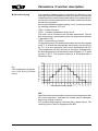
1
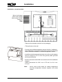
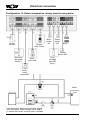
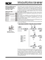
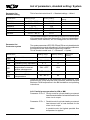
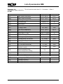
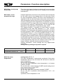
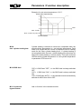
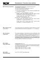
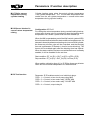
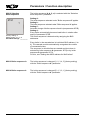
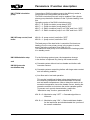
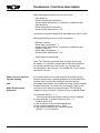
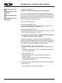
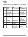
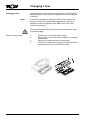
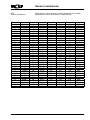
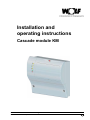
Installation and operating instructions Cascade module KM Wolf GmbH · Postfach 1380 · 84048 Mainburg · Tel. 08751/74-0 · Fax 08751/741600 · Internet: www.wolf-heiztechnik.de Part no. 30 62 449 Subject to modifications 03/09 GB Index Safety instructions.......................................................................3 Standards / Regulations..............................................................4 Terminology ...........................................................................5 Abbreviations / Equipment description........................................6 Installation ...........................................................................7 Configuration overview................................................................9 Electrical connection............................................................. 8-22 Config. 1: Mixer circuit and cylinder circuit.......................10 Config. 2: Mixer circuit and convector heater circuit.........11 Config. 3: Mixer circuit and heating circuit........................12 Config. 4: Cylinder circuit and third party boiler control....13 Config. 5: Mixer circuit and return temperature raising for central heating backup.....................................14 Config. 6: Heating circuit and return temperature raising for soft starting......................................15 Config. 7: Mixer circuit with indirect return temperature raising for soft starting......................................16 Config. 8: Mixer circuit (factory setting)............................17 Config. 9: Heating circuit..................................................18 Config. 10: Cylinder circuit.................................................19 Config. 11: Convector heater circuit...................................20 Config. 12: 0 – 12 V input for telecontrol system................21 Config. 13: Return temperature raising, wood burning boiler..22 Commissioning guidelines............................................... 23-24 Setting the eBUS address of the extension and control modules (KM, MM and BM)...........................................25 Setting of the eBUS address for Wolf boilers............................26 Switching times.........................................................................27 List of parameters, standard setting / System...........................28 List of parameters MM...............................................................29 List of parameters KM ........................................................ 30-31 Parameters / Function description MM................................ 32-37 Parameters / Function description KM................................ 38-51 Additional functions / Reset.......................................................52 Header frost protection..............................................................52 Cylinder frost protection............................................................52 Anti-seizing pump protection.....................................................52 Anti-seizing mixer protection ...................................................52 2 3062449_0309 Index / Safety instructions Emissions test .........................................................................52 Loading the standard values (reset)..........................................51 Fault codes .........................................................................53 Changing a fuse........................................................................54 Sensor resistances....................................................................55 Specification .........................................................................56 Keyword index ................................................................... 57-58 Safety instructions The following symbols are used in conjunction with these important instructions concerning personal safety, as well as operational reliability. "Safety instructions" are instructions with which you must comply exactly, to prevent risks and injuries to individuals and material losses. Danger through 'live' electrical components. Switch OFF the ON / OFF switch before removing the casing. Never touch electrical components or contacts when the ON / OFF switch is in the ON position. This results in a risk of electrocution that may lead to injury or death. The main supply terminals are 'live' even when the ON / OFF switch is in the OFF position. Note 3062449_0309 "Note" indicates technical instructions that you must observe to prevent material losses and boiler malfunctions. 3 Standards / Regulations Standards and regulations The appliance and control accessories comply with the following regulations: EC Directives - 2006/95/EC Low Voltage Directive - 2004/108/EC EMC Directive EN Standards - EN 60730-1 - EN 55014-2 - EN 60529 Installation / Commissioning - According to DIN EN 50110-1, only qualified electricians may carry out the installation and commissioning of the heating control unit and connected accessories. - Observe all regulations stipulated by your local power supply utility and all VDE or local regulations. - DIN VDE 0100 regulations regarding the installation of high voltage systems up to 1 000 V - DIN VDE 0105-100 operation of electrical systems Warnings - Never remove, bypass or disable safety and monitoring equipment. - Only operate the system in perfect technical condition. Immediately remove / remedy any faults and damage that may impact on safety. - Always ensure that cold water is mixed in with hot water, when the DHW temperature is set above 60 °C or when pasteurising at a temperature in excess of 60 °C (risk of scalding). Maintenance / Repair - Regularly check the perfect function of all electrical equipment. - Only qualified personnel may remove faults or repair damage. - Only replace faulty components or equipment with original Wolf spare parts. - Always maintain prescribed electrical protection values (see specification). Note 4 Any damage or loss resulting from technical modifications to Wolf control units is excluded from our warranty. 3062449_0309 Terminology Terminology Header temperature The header temperature is the flow temperature in the header downstream of the low loss header. The header temperature therefore corresponds to the heating water temperature of heating systems equipped with a gas fired boiler. Heating water temperature The heating water temperature is the radiator flow temperature. The higher the heating water temperature, the higher the heat transfer to radiators. mixer circuit temperature The mixer circuit temperature is the flow temperature downstream of the mixer, with which underfloor heating systems are supplied. Cylinder heating Heating up a DHW cylinder. Heating program Subject to program selection, the heating time program switches from heating to economy mode or from heating mode to heating OFF and vice versa. Domestic hot water program The DHW time program switches "Enable DHW cylinder heating" ON and OFF. Winter mode Central heating and DHW according to the heating and DHW time program. Summer mode Central heating OFF, DHW according to the DHW time program. Heating mode / Setback mode In winter mode, two heating water temperatures can be selected, i.e. standard room temperature and setback temperature. In the latter case the temperature will be reduced to the setback temperature. The heating program changes over between heating and setback mode. 3062449_0309 5 Abbreviations / Equipment description Abbreviations SAF - Header sensor BPF - Bypass sensor MKF - Mixer circuit sensor PF - Buffer sensor PK - zero volt contact RLF - Return sensor SPF - Cylinder sensor VF - Flow sensor BS - Boiler sensor StE - Fault message input (PK as N/O) 0-10 V - Voltage input for ext. demand MKP - Mixer circuit pump MM - Mixer motor or mixer module SPLP - Cylinder primary pump LP - Primary pump BPP - Bypass pump 3WUV - Three-way diverter valve StA - Fault message ouput (PK as N/C) CIR. - DHW circulation pump HKP - Heating circuit pump Appliance description The cascade module (KM) comprises a cascade control for switching and modulating boilers. Only boilers of the same type (single stage, two-stage or modulating) and of the same output may be linked in a single cascade. The active boilers transfer the generated heat into the low loss header or the heating system headers, whereby the heat is captured by the header sensor, the so-called common flow sensor of the heating system. The KM module also comprises a mixer circuit control and the control for a programmable output. The mixer circuit controller can be used for the heating flow as well as for the heating return. The programmable output either regulates a direct heating circuit, a cylinder circuit, a convector heater (= ext. heat demand), or a three-way diverter valve for raising the return temperature (= central heating backup). The outputs for the mixer circuit control can also be configured as DHW circulation pump and fault message output. Subject to application, select the relevant combination of mixer circuit controller or outputs and the programmable output as configuration. For connection to telecontrol systems, the KM offers a 0 to 10 V input with which to control the boilers. With this configuration only the fault message output is still enabled. Parameters can be changed and sensor values can be displayed at the programming module (BM) or at ISM1 with WRS-Soft. The KM features an eBUS interface (2-wire communication BUS) and can therefore be integrated into the Wolf control system. 6 3062449_0309 Installation Installation, cascade module 10.5 cm Mixer circuit pump Mixer motor OPEN Mixer motor CLOSE Output A1 eBUS Fault 12.5 cm - Remove the cascade module from its packaging. - Fitting directly to the wall. - Connect one outside temperature sensor to boiler 1 (address 1; boiler addressing, see page 26); alternative connection options see under "Electrical connection / Outside temperature sensor". - Install the outside temperature sensor at a north or north eastern wall at a height of 2-2.5 m from the ground (cable grommet pointing downwards). - Wire the cascade module KM in accordance with the installation diagram. Cable cross-section for 230 V min. 0.75 mm²; for 24 V min. 0.5 mm². Note: 3062449_0309 Never route on-site leads for outside temperature and flow temperature sensors together with mains cables. 7 Electrical connection Maximum thermostat When connecting the maximum thermostat at the "Max TH" terminals of the KM, only the mixer circuit pump will be stopped in case of faults (mixer no longer closes). Without a maximum thermostat, extremely high temperatures may occur in the underfloor heating circuit, should the KM develop a fault. This can result in the floor developing cracks. If with the configurations 1, 2, 3, 4, 5, 7, 8 and 13 no maximum thermostat is connected, plug a 3-pole Rast5 plug with jumper in its place. Fault message input With all configurations except configuration 5, the grey 2-pole plug with jumper must be plugged into input "E2" if the fault input is not used. Outside temperature sensor There are four options for integrating an outside temperature sensor into a system: a) Outside temperature sensor at boiler 1 (address 1) at terminal AF, part no. 2792021. b) Outside temperature sensor at BM (address 0) in the wall mounted base at terminal 5/6, part no. 2792021. c) Radio clock module with outside temperature sensor connected to the eBUS, part no. 2792325. d) Wireless outside temperature sensor and radio receiver connected to the eBUS, part no. 2744081 and 2744209. Recommended cables and minimum cable cross-sections: H05VV 3x1.0 mm² H05VV 3x0.75 mm² H05VV 3x0.75 mm² H05VV 4x0.75 mm² H05VV 2x0.5 mm² Note: During service work, isolate the entire system from the power supply, otherwise there will be a risk of electrocution. 8 power cable mixer circuit pump max. thermostat, three-way diverter valve mixer motor BUS cable 3062449_0309 Configuration overview Configuration overview Subject to the application of the KM, 13 different system versions are available. The different versions can be set with the configuration parameter (KM01). This is found at control level 2 → Contractor → Cascade Configuration 01: Mixer circuit and cylinder circuit; page 10 Configuration 02: Mixer circuit and convector heater circuit; page 11 Configuration 03: Mixer circuit and heating circuit; page 12 Configuration 04: Cylinder circuit and third party boiler control, page 13 Configuration 05: Mixer circuit and return temperature raising for central heating backup; page 14 Configuration 06: Heating circuit and return temperature raising for soft starting, page 15 Configuration 07: Mixer circuit with indirect return temperature raising for soft starting; page 16. Applies exclusively to systems comprising mixer circuits. Configuration 08: Mixer circuit (factory setting); page 17 Configuration 09: Heating circuit; page 18 Configuration 10: Cylinder circuit; page 19 Configuration 11: Convector heater circuit; page 20 Configuration 12: 0 – 10 V input for telecontrol system, page 21 Configuration 13: Return temperature raising, wood burning boilers; page 22 Note: 3062449_0309 Restart the system after every configuration change (mains "OFF"/mains "ON"). 9 Electrical connection Configuration 1: Mixer circuit and cylinder circuit Cylinder primary pump SPLP Power 230 VAC Maximum thermostat max. TH 1) Flow Cylinder sensor SPF sensor; mixer circuit VF Fault message input StE (N/C)2) Mixer motor MM Mixer circuit pump MKP Boiler Header sensor SAF DHW cylinder Mixer circuit SPLP Heating flow Heating return 1) 2) see description "Maximum thermostat" page 8 see description "Fault message input" page 8 10 3062449_0309 Electrical connection Configuration 2: Mixer circuit and convector heater circuit Primary pump LP Power 230 VAC Zero volt contact PK Flow sensor; mixer circuit VF Boiler Header sensor SAF Maximum thermostat max. TH 1) Fault message input StE (N/C)2) Mixer motor MM Mixer circuit pump MKP Convector heater circuit Mixer circuit Heating flow Heating return 1) 2) see description "Maximum thermostat" page 8 see description "Fault message input" page 8 3062449_0309 11 Electrical connection Configuration 3: Mixer circuit and heating circuit Heating circuit pump HKP Power 230 VAC Flow sensor; mixer circuit VF Boiler Header sensor SAF Maximum thermostat max. TH 1) Fault message input StE (N/C)2) Mixer motor MM Mixer circuit pump MKP Mixer circuit Heating circuit Heating flow Heating return 1) 2) see description "Maximum thermostat" page 8 see description "Fault message input" page 8 12 3062449_0309 Electrical connection Configuration 4: Cylinder circuit and third party boiler control Cylinder primary pump SPLP Power 230 VAC Maximum thermostat max. TH1) Fault DHW message circulation output StA pump ZKP Burner control BSt Cylinder sensor SPF e.g. mixer module MM Header sensor SAF Fault message input StE (N/C)2) DHW cylinder External boiler 1) 2) see description "Maximum thermostat" page 8 see description "Fault message input" page 8 3062449_0309 13 Electrical connection Configuration 5: Mixer circuit and return temperature raising for central heating backup Buffer sensor PF Power 230 VAC Diverter valve 3 WUV Flow sensor VF; mixer circuit Boiler Return sensor RLF Header sensor SAF Maximum thermostat max. TH 1) Mixer motor MM Mixer circuit pump MKP Mixer circuit Buffer Heating flow Heating return 1) see description "Maximum thermostat" page 8 14 3062449_0309 Electrical connection Configuration 6: Heating circuit and return temperature raising for soft starting Heating circuit pump HKP Power 230 VAC Return sensor RLF Boiler Header sensor SAF Maximum thermostat max. TH 1) Mixer motor MM Mixer circuit pump MKP Fault message input StE (N/C)2) Heating circuit Heating flow Heating return 1) 2) see description "Maximum thermostat" page 8 see description "Fault message input" page 8 3062449_0309 15 Electrical connection Configuration 7: Mixer circuit with indirect return temperature raising for soft starting Return Flow sensor RLF sensor, mixer circuit VF Power 230 VAC Boiler Header sensor SAF Maximum thermostat MaxTH 1) Mixer motor MM Mixer circuit pump MKP Fault message input StE (N/C)2) Mixer circuit Heating flow Heating return 1) 2) see description "Maximum thermostat" page 8 see description "Fault message input" page 8 16 3062449_0309 Electrical connection Configuration 8: Mixer circuit (factory setting) Flow sensor, mixer circuit VF Power 230 VAC Boiler Header sensor SAF Maximum thermostat MaxTH 1) Mixer motor MM Mixer circuit pump MKP Fault message input StE (N/C)2) Mixer circuit Heating flow Heating return 1) 2) see description "Maximum thermostat" page 8 see description "Fault message input" page 8 3062449_0309 17 Electrical connection Configuration 9: Heating circuit Power 230 VAC Heating circuit pump HKP Boiler Header sensor SAF Fault message input StE (N/C)2) Heating circuit Heating flow Heating return 2) see description "Fault message input" page 8 18 3062449_0309 Electrical connection Configuration 10: Cylinder circuit Power 230 VAC Cylinder sensor SPF Boiler Cylinder primary pump SPLP Header sensor SAF Fault message input StE (N/C)2) DHW cylinder Heating flow Heating return 2) see description "Fault message input" page 8 3062449_0309 19 Electrical connection Configuration 11: Convector heater circuit Power 230 VAC Primary pump LP Zero volt contact PK Boiler Header sensor SAF Fault message input StE (N/C)2) Convector heater circuit Heating flow Heating return 2) see description "Fault message input" page 8 20 3062449_0309 Electrical connection Configuration 12: 0 – 10 V input for telecontrol system Boiler Power 230 VAC Fault message output SA Fault message input StE (N/C)2) Header sensor SAF 0-10 VDC input 0-10 V from DDC system Heating flow Heating return 2) see description "Fault message input" page 8 3062449_0309 21 Electrical connection Configuration 13: Return temperature raising, wood burning boiler Power 230 VAC Diverter valve 3 WUV Boiler sensor KF Return sensor RLF Boiler 3) Header sensor SAF Maximum thermostat MaxTH 1) Mixer motor MM Fault message input StE (N/C)2) Mixer circuit pump MKP Buffer see description "Maximum thermostat" page 8 see description "Fault message input" page 8 3) if a boiler with WOLF control system is installed 1) 2) 22 3062449_0309 Commissioning Commissioning guidelines Implement the following steps in the order in which they are listed to achieve a successful commissioning with regards to addressing and programming all control components and the system configuration. Note: HG, KM, MM and SOL parameters are found at control level 2 → Contractor → Boiler (HG) / Cascade (KM) / Mixer (MM) / Solar (SOL) in the BM Step 1 Step 2 Step 3 Step 4 Step 5 Implement the "Installation" and "Electrical connection" of all extension and programming modules in accordance with the instructions in the associated manual. For further details regarding the eBUS address (DIP switches) of the extension and programming modules (KM, MM and BM), see "Setting the eBUS address of the extension and programming modules (KM, MM and BM)". Start the system via the system ON/OFF switch (mains "ON"). For setting the eBUS address at WOLF boilers, see the details in "Setting the eBUS address for WOLF boilers". Configuration of the extension modules, such as cascade module, mixer module and solar module 1. Configuration of the cascade module KM a) Parameter KM01 (= configuration): Here, select the configuration of the KM in accordance with the actual hydraulic connection. See “Electrical connection” regarding the selection of the correct configuration. b) Parameter KM02 (= mode): Select one of the following settings subject to the boiler type and the burner operating mode (par. HG 28). KM02 = 1 ⇒ single stage boiler KM02 = 2 ⇒ two-stage boiler KM02 = 3 ⇒ modulating boiler 2. 3062449_0309 Configuration of the mixer module MM and solar module SM2 parameter MI05 (= configuration mixer module) or parameter SOL12 (= configuration solar module): Here, you configure the mixer modules and the solar module in accordance with the hydraulic layout. See "Electrical connection" in the mixer module or solar module installation instructions regarding the selection of the correct configuration. 23 Commissioning Step 6 Configuration Wolf boiler control unit COB Parameter HG06 (pump operating mode): Select pump operating mode 1 in conjunction with Wolf boiler control unit COB. ⇒ HG06 = First description see COB control unit manual. Note: Parameter HG06 must not be changed for Wolf control units for wall mounted boilers and MGK standard control units. Step 7 Programming the following components 1. Wolf boiler control unit COB, Wolf control unit for wall mounted boilers and MGK standard control unit Set parameter HG22 (maximum boiler temperature) = parameter KM03 (maximum header temperature) to + 5 K. 2. BM programming module Set parameters such as time, day, time programs, etc. 3. Extension modules KM, MM and SM Match the parameters to the specific requirements. Start the system again via the system ON/OFF switch (mains "OFF/ ON"). The system is ready to operate after approx. 3 min. Step 8 After the successful commissioning, the number of boilers appears on the BM below the current time. 24 3062449_0309 Setting the eBUS address of the extension and programming modules (KM, MM, BM) Setting the eBUS address of the extension and programming modules (KM, MM and BM) Setting the eBus Address 0 Address 1 (factory setting) Address 2 Address 3 Address 4 Address 5 Address 6 Address 7 The address of the cascade module KM remains set to 1 (factory setting). In addition to the KM, up to six mixer modules MM can be connected to a single system. The MM addresses are assigned in sequence from 2 to 7 in conjunction with the Wolf control unit for wall mounted boilers, MGK standard control unit or the Wolf boiler control unit COB. The functions of each cascade module and each mixer module are determined via the configuration settings (see also "Electrical connection"). Each system can comprise up to seven mixer circuits and one direct heating circuit. Consequently, configuration 3 or 9 may only be assigned once per system, irrespective of whether in the cascade or mixer module. In addition to each mixer module (mixer circuit) one BM programming module can be used to provide full control. The direct heating circuit is always regulated by the programming module with address 0. a) max. expansion with Wolf control unit for wall mounted boilers, MGK standard controller or Wolf boiler control unit COB HC Wolf boiler BM MK 1 KM BM option Display example: BM (factory setting) MK 2 2 MM 1 MM BM 3 MM 4 MM option 5 MM MK 7 6 MM BM option The KM can also be used as stand-alone mixer circuit controller, if no boiler is installed. For this, either an outside temperature sensor must be connected to the BM (0) or a DCF receiver with outside temperature sensor must be connected to the eBUS; see also "Electrical connection/outside temperature sensor". The KM, MM and BM addresses are set in accordance with the scheme including Wolf boilers. 3062449_0309 25 Setting the eBUS address for Wolf boilers Setting of the eBUS address When operating several boilers (number of boilers >1) in conjunction for Wolf boilers with a cascade module, set the eBUS address for each boiler in accordance with the table below. Boiler BUS address Rotary selector position DHW Illuminated ring indication Individual boiler 0* 6 flashing green (factory setting) 1 1 1 flashing red 2 2 2 flashing yellow 3 3 3 flashing yellow/red 4 4 4 flashing yellow/green 5 5 5 flashing green/red * Address 0 cannot be changed at the Wolf boiler control unit COB. If only one Wolf boiler control unit COB is installed in the system, then the address remains at its factory setting (address = 1). BUS address setting Hold down the reset button; after 5 seconds, the corresponding flashing code will be displayed (see table). Select the corresponding address with the DHW temperature rotary selector. Then release the reset button again. The assignment of gas fired boilers or BUS addresses (1), (2), (3) and (4) must be made on-site. Allocate each BUS address only once. Reset button Temperature selection DHW Setting parameters 26 Note: If only one BUS subscriber (boiler or KM) is isolated from the power supply, then stop and start all subscribers via a system switch. The standard settings for all parameters and switching times are fixed and stored in a non-volatile memory. All changes are permanently stored and will not be lost, even if the power fails for several weeks. Parameters are programmed via the BM programming module. Check the description of operation and setting / modifying parameters in the BM installation and operating instructions. 3062449_0309 Switching times Switching times Mixer circuit: The switching times for the mixer circuit in the cascade module are stored in the cascade module. This is found at control level 2 → Time program → Heating system → Mixer 1 Heating circuit and cylinder: The switching times for the heating circuit and cylinder are always stored in the BM programming module. Time BlockSwitchingMixer Time Block SwitchingMixer mode t ime mode time ON OFF ON OFF Time prog. 1 Mo-Su 1 5:00 21:00 Time prog. 3 MON 1 4:30 20:00 2 2 3 3 Sa-Su 1 6:00 22:00 TUE 1 4:30 20:00 2 2 3 3 Time prog. 2 Mo-Fr 1 5:00 7:00 WED 1 4:30 20:00 2 14:00 21:00 2 3 3 Sa-Su 1 6:00 21:00 THU 1 4:30 20:00 2 2 3 3 FRI 1 4:30 20:00 2 3 SAT 1 4:30 20:00 2 3 SUN 1 4:30 20:00 2 3 3062449_0309 27 List of parameters, standard setting / System Parameter list Standard setting Parameters TEMP DAY RED TEMP GRADIENT ROOM INFL W/S SWITCh ECO-RED This is found at control level 2 → Standard settings → Mixer 1 Setting range Individual setting Factory setting 5 °C - 30 °C 5 °C - 30 °C 0-3 OFF - ON 0 °C - 40 °C -10 °C - 40 °C 20°C 16 °C 0.8 OFF 20 °C 10 °C Check the BM installation and operating instructions for a description of the parameters Standard temperature, Reduced temperature, Gradient, Room influence, WI / SU changeover and ECO-RED. Parameter list Contractor system The system parameters A09, a10, a12 and a14 can only be adjusted at the programming module with address 0. All other system parameters are adjusted at the associated programming modules. This is found at control level 2 → Contractor → System Parameters A00 A09 a10 Setting range Room influence Frost protection limit Parallel pump operation a12 Room temperaturedependent summer/ winter changeover Setback stop a14 Maximum DHW temperature a11 Factory setting 1 - 20 4 -20 - 10 °C 2 0-1 0 ON - OFF ON OFF, -39 °C -16 60 - 80 °C 65 Individual setting Check the description of the parameters Room influence, Frost protection limit, Pump stop with room controller, Setback stop and Maximum DHW temperature in the BM installation and operating instructions. A10: Parallel pump operation for KM or MM Parameter a 10 = 0: Priority mode for cylinder heating or external heat demand ahead of a heat demand for the mixer circuit output. Parameter a 10 = 1: Parallel mode for cylinder heating or external heat demand with a heat demand for the mixer circuit output. Note: 28 In parallel mode, the highest possible flow temperature is applied. 3062449_0309 List of parameters MM Parameter list This is found at control level 2 → Contractor → Mixer 1 Contractor, mixer circuit in the KM Parameters MI01 MI02 MI03 MI04 MI05 MI06 MI07 MI08 MI09 MI10 MI11 MI12 MI13 MI14 MI15 MI16 MI17 MI18 Setting range Factory setting Min. mixer circuit temp 0 °C - 80 °C 0 °C Max. mixer circuit temp 20 °C - 80 °C 50 °C Heating curve gap 0 K - 30 K 10 K Screed drying 0 (OFF) - 2 0 - ---- 0 - 30 min 5 min No function Run-on time, heating circuit P range, mixer Set return temperature Max. cylinder heating time BUS feed (1 = ON) Hysteresis, bypass sensor Primary pump, blocking Primary pump, run-on time Constant temperature 5 K - 40 K 12 K 20 °C - 80 °C 30 °C 0-5h 2h 0 (OFF) - 2 (Auto) 2 0 °C - 30 °C 10 °C 0-1 0 0 - 10 min 3 min 50 °C - 80 °C 75 °C dT OFF (stop differential) 3 - 20 K 5 K dT ON (start differential) 5 - 30 K 10 K 0 - 40 K 10 K 0s 0s Boiler overtemperature during cylinder heating Burner blocked during return temperature raising MI50 Test function 1-8 Display of the input sensor values 1 MI70 MI71 MI72 Analogue input E1 - - Analogue input E2 - - Analogue input, flow sensor - - 3062449_0309 29 List of parameters KM Parameter list Contractor cascade This is found at control level 2 → Contractor → Cascade Setting range Factory setting 1 13 8 KM02 Configuration Mode (single stage = 1; two-stage=2; modulating = 3) 1 3 3 KM03 Maximum header temperature 50 °C 85 °C 85 °C 40 °C 85 °C 75 °C 20 °C 2K 0 min 70 °C 20 K 30 min 20 °C 5K 5 min 10 h 2000 h 200 h 20 K/% 500 K/% 100 K/% 20 K/% 500 K/% 100 K/% 5s 500 s 50 s [AbCd] [12345] [12345] 10% 70% 0 [54321] [54321] 60% 100% 3 d [12345] [54321] 30% 80% 0 0 1 0 0 10 K 1 50 K 0 10 K 0 1 0 0K 0 40 °C 10 K 5K 20 °C 20 K 1 80 °C 50 K 40 K 80 °C 5K 0 65 °C 40 K 15 K 60 °C 2K 30 K 10 K 20 °C 2K 1 80 °C 30 K 2 60 °C 10 K 1 1 5 1 Parameters KM01 KM21 KM22 KM23 KM24 KM25 KM26 KM27 KM28 KM29 KM30 KM31 Maximum flow temperature, central heating Minimum header temperature Set hysteresis - header temperature Off-periods STD up to the boiler sequence change 1/Kp header temperature control start 1/Kp header temperature control stop Tn header temperature control Selection, boiler sequence Boiler sequence A Boiler sequence B Shutdown modulation level Start-up modulation level DHW circulation pump Pump control lead boiler Modulation stop Hysteresis, modulation stop Forced output for cylinder heating Hysteresis, parallel operation Pump speed control WZ Min. flow temperature WZ Max. spread WZ P range, pump Set boiler water temperature Hysteresis, set boiler water temperature Set buffer temperature Hysteresis, set buffer temperature Operating mode 0 -10 V input KM50 Test function KM04 KM05 KM06 KM07 KM08 KM09 KM10 KM11 KM12 KM13 KM14 KM15 KM16 KM17 KM18 KM19 KM20 30 Individual settings 3062449_0309 List of parameters KM Display KM60 KM61 KM62 KM70 KM71 KM72 KM73 KM74 3062449_0309 Control deviation Overall modulation level Modulation level, boilers E1 E2 VF SAF 0 - 10 V - - - - 31 Parameters / Function description With the r.h. rotary selector, choose the mixer parameter to be modified (MM..) from the contractor menu level (after entering the correct code). The mixer parameter to be modified (MM..) is changed by pressing (display indication flashes) and then turning the r.h. rotary selector. After setting the mixer parameter to be modified (MM..), pressing the r.h. rotary selector again confirms the setting. Pressing the Info pushbutton returns the standard display. MI 01 minimum mixer circuit temperature This minimum mixer circuit temperature limits the low end of the set mixer circuit flow temperature. MI 02 maximum mixer circuit temperature The maximum mixer circuit temperature limits the set flow temperature of the mixer circuit upwards, for example to prevent damage to floor coverings. This does not replace the maximum thermostat for pump shutdown. MI 03 Heating curve gap The heating water temperature will be raised by the set value against the mixer circuit temperature. 32 3062449_0309 MI 04 Screed drying If an underfloor heating system is started for the first time in new buildings, the set flow temperature may, as an option, be controlled independent of the outside temperature either to a constant value or to control the set flow temperature in accordance with an automatic screed drying program. If this function has been enabled (setting 1 or 2), it can be terminated by resetting parameter MI 04 to 0. MI 04 = 0 without function MI 04 = 1 constant temperature mixer circuit The mixer circuit is heated to the set flow temperature. The set flow temperature is permanently set to the temperature selected in parameter MI 01. MI 04 = 2 screed drying function For the first two days, the set flow temperature will remain constant at 25 °C. It will then be automatically raised every day (at 0:00 h) by 5 °C up to the maximum mixer circuit temperature (MI 02). That temperature will then be held for two days. Subsequently, the flow temperature is automatically reduced again in 5 °C steps per day to 25 °C. The program sequence is terminated after a further two days. Fig.: Flow temperature progress over time during screed drying Flow temperature (°C) Parameters / Function description Screed drying runtime (days) NB: Agree the time sequence and the maximum flow temperature with the screed contractor, otherwise the screed may be damaged, particularly through cracking. The screed drying program continues after a power failure. The remaining time in days is displayed at the BM. 3062449_0309 33 Parameters / Function description MI 06 Mixer circuit pump run-on time The mixer circuit pump / heating circuit pump will run on according to the set value after the mixer circuit / heating circuit has been switched OFF. MI 07 Mixer circuit proportional range Subject to application, the mixer circuit controller can be configured for the mixer circuit in the heating flow or for the mixer circuit for return temperature raising. The mixer circuit temperature is regulated to the set value by means of the mixer circuit sensor / return temperature sensor (mixer circuit in the heating flow / mixer circuit for raising the return temperature) via terminal VF and a motorised mixer. The output of the mixer controller for regulating the mixer motor features P characteristics. The P range can be adjusted for each parameter "Proportional range, mixer". The impulse duration (= activation of mixer motor) is directly proportional to the mixer flow deviation (∆T = Set - Actual). Parameter MI 07 determines the temperature deviation, for which the pulse duration is 100%. Outside this range the mixer is either not regulated at all (∆T < 1 K) or is regulated constantly (∆T > as setting for par. MI 07) headed for. Within the temperature range, the system exerts constant control. Adjust the proportional range so that stable regulation is ensured. This depends on the runtime of the mixer motor. For mixer motors with a short runtime, select a wide proportional range and vice versa for mixer motors with longer runtimes, select a narrower proportional range. Setting information: These settings are only approximate guidelines. Change factory settings only where required. Mixer runtime in min. 2-3 4-6 7 - 10 Temperature window in K 25 - 14 15 - 9 10 - 5 MI 08 Set return temperature 34 MI 07 Configuration km 01 = 7 The return temperature is permanently monitored. If the return temperature falls too low, all mixers will be forced to raise the return temperature. Falling return temperature: RL_ist < RL_Set + hysteresis, return temperature ⇒ all mixers towards "CLOSE" RL_ist < RL_Set ⇒ mixer towards "CLOSE" and all heating circuit and cylinder primary pumps "OFF" Rising return temperature: RL_ist < RL_Set + 2 K ⇒ all mixers towards "CLOSE" RL_ist < RL_Set + hysteresis, return temperature + 4 K ⇒ no forced output Hysteresis, return temperature = 8 K 3062449_0309 Parameters / Function description Example of a set return temperature = 30 °C: Actual return temperature [K] Time Mixer "CLOSE" Mixer "CLOSE" and pump "OFF" Forced actuation MI 09 max. cylinder heating time Cylinder heating is deemed to have been completed when the actual cylinder temperature is ≥ set cylinder temperature. Fault code 52 is issued and the control unit switches over to heating mode for the "Max. cylinder heating time", if cylinder heating is not completed within the max. cylinder heating time (this does not apply to the status heating = summer mode). This cycle continues until the actual cylinder temperature is ≥ set cylinder temperature or parameter MI 09 is set to 0. MI 10 BUS feed MI 10 = 0: BUS feed "OFF", i.e. the BUS feed is always switched OFF. MI 10 = 1: BUS feed "ON", i.e. the BUS feed is always switched ON. MI 10 = 2: BUS feed “AUTO”, i.e. the cascade module automatically switches the BUS feed ON or OFF. MI 11 Hysteresis bypass sensor 3062449_0309 Has no function in the cascade module 35 Parameters / Function description MI 12 Primary pump block For starting the primary pump, cylinder primary pump (configuration 1, 4 and 10) Or for ext. heat demand (configuration 2 and 11), we differentiate between two cases: a) Par. MI 12 = 0: The primary pump is started immediately after the demand is issued. b1)Par. MI 12 = 1 with configuration 1, 4 and 10: Primary pump "ON": Primary pump “ON”: actual header temperature > actual cylinder temperature + 5 K Primary pump "OFF": Actual header temperature ≤ actual cylinder temperature + 2 K b2) Par. MI 12 = 1 with configuration 2 and 11: Primary pump "ON": Primary pump “ON”: Actual header temperature > Constant temperature - 5K Primary pump "OFF": Primary pump “OFF”: Actual header temperature > Constant temperature - 8 K MI 13 Primary pump run-on time The primary pump run-on starts after cylinder heating or ext. heat demand has been terminated (configuration 1, 2, 4, 10 and 11). MI 14 Constant temperature The system regulates to the selected set flow temperature, and output A1 is regulated in case of an external heat demand via a zero volt contact at input E1 and parameter configuration = 2 or 11. External heat demand takes priority over any heat demand from the heating circuits. The primary pump run-on starts after the external heat demand has terminated. The program selector and time slot heating or DHW have no influence. MI 15 dTAus (stop differential) Configuration km 01 = 5 Configuration 5 comprises a mixer circuit control and a dT control for central heating backup. Condition for central heating backup, see parameter description mi 18. Output 1 ON, if PF_ist > RLF_ist + dTEin Output 1 OFF, if PF_ist < RL_ist + dTAus MI 16 dTEin (start differential) See "MI 15 = dTOFF (stop differential)" 36 3062449_0309 Parameters / Function description MI 17 Boiler excess temperature during cylinder heating Cylinder heating starts when the actual cylinder temperature < set cylinder temperature - 5 K. The set flow temperature then results from the set cylinder temperature + excess boiler water temperature during cylinder heating. MI 18 Burner blocked in case of return temperature raising Configuration km 01 = 5 For raising the return temperature during central heating backup, a three-way diverter valve is controlled to raise the heating return temperature via a buffer cylinder that has been heated up. When the KM is operated as part of the Wolf control system WRS, the boilers are blocked when the start conditions have been met. If a demand is issued by at least one heating circuit or one DHW cylinder, the three-way diverter valve will be controlled, and the blocking time set in parameter MI 18 starts (= time for burner blocking). The burner will be enabled again after the blocking time has expired. When the start condition has been met whilst the burner is already enabled, it will be disabled for the set time. Start condition: PF_ist (E1) > RLF_ist (E2) + dTEin (MI 16) Stop condition: PF_ist (E1) < RLF_ist (E2) + dTAus (MI 15) When setting a blocking time of 0 s (MI 18) the three-way diverter valve will be controlled independent of a heat demand. MI 50 Test function 3062449_0309 Parameter MI 50 enables control over individual relays. MI 50 = 1 ⇒ Control, mixer circuit pump relay MKP MI 50 = 2 ⇒ Control, mixer motor relay "OPEN" MM MI 50 = 3 ⇒ Control, mixer motor relay "CLOSE" MM MI 50 = 4 ⇒ Control, output relay A1 37 Parameters / Function description Note: Only contractors should adjust the KM parameters. With the r.h. rotary selector, choose the cascade parameter to be modified (KM..) from the contractor menu level (after entering the correct code). The cascade parameter to be modified (KM..) is changed by pressing (display indicator flashes) and then turning the r.h. rotary selector. After setting the cascade parameter to be modified (KM..), pressing the r.h. rotary selector again confirms the setting. Pressing the Info pushbutton returns the standard display. KM 01 Configuration The corresponding configuration may, subject to the application of the KM, have to be selected. Up to 13 configurations can be selected. corresponding wiring diagrams, see under "Electric connection". Adjust the configuration during commissioning. Configuration 01: Configuration 02: Configuration 03: Configuration 04: Configuration 05: Configuration 06: Configuration 07: Configuration 08: Configuration 09: Configuration 10: Configuration 11: Configuration 12: Configuration 13: KM 02 Mode Mixer circuit and cylinder circuit Mixer circuit and convector heater circuit Mixer circuit and heating circuit Cylinder circuit and third party boiler control Mixer circuit and return temperature raising for heating backup Heating circuit and return temperature raising for soft starting Mixer circuit with indirect return temperature raising for soft starting Mixer circuit (factory setting) Heating circuit Cylinder circuit Convector heater circuit 0 – 10 V input for telecontrol system Return temperature raising, wood burning boiler Only operate boilers of the same type in a single cascade, i.e. either modulating, single stage or two-stage boilers. Adjust the configuration during commissioning. km 02 = 1 ⇒ single stage boiler km 02 = 2 ⇒ two-stage boiler km 02 = 3 ⇒ modulating boiler (factory setting) KM 03 Maximum header temperature 38 The "Maximum header temperature" parameter limits the set header temperature upwards. 3062449_0309 Parameters / Function description KM 04 Maximum flow temperature The "Maximum flow temperature" parameter limits the set header temperature of the heating circuits (mixer circuits and direct heating circuits) upwards. Parameter km 03 takes priority. KM 05 Minimum flow temperature The "Minimum header temperature" parameter limits the set header temperature downwards. KM 06 Hysteresis header temperature If only one boiler/burner stage is still in operation, that boiler/ burner stage will be shut down if the following applies: Actual header temperature > set header temperature + hysteresis. KM 07 Blocking time A blocking time is provided that prevents further boilers/heating stages from being started, to prevent boilers/heating stages frequently cycling ON and OFF. An additional boiler/burner stage can only be started after the blocking time has expired. This blocking time does not apply to the lead boiler, if there is a DHW demand or convector heater demand from the cascade or mixer modules. KM 08 Hours until a boiler sequence change After the adjustable burner hours run figure has expired, the current lead boiler changes, if parameter KM 08 "Setting C" has been selected, the boiler sequence between A and b; when "Setting d" has been selected, the next boiler in rotation becomes the lead boiler. That boiler is lead boiler, whose cascade module is switched ON first in the cascade and is shut down last. Precondition for an automatic changeover of boiler sequence is the selection of a boiler sequence (parameter KM 12) = C or d. The internal hours run meter for the boiler sequence changeover is saved daily (0:00 h) to a non-volatile memory. The last value saved is downloaded in case of power failure. Any reset at the KM (= loading standard values) returns the internal hour count to zero. KM 09 1/Kp header temperature control start Setting the P portion of the PI controller for header temperature. Parameter value km 09 increase ⇒ header temperature control responds more slowly Parameter value km 09 reduce ⇒ Header temperature control responds more quickly KM 10 1/Kp Header temperature control stop Setting the P portion of the PI controller for header temperature. For a description, see parameter km 09 KM 11 Tn Header temperature control Setting the I portion of the PI controller for header temperature. Parameter value km 11 increase ⇒ header temperature control responds more slowly Parameter value km 11 reduce ⇒ header temperature control responds more quickly 3062449_0309 39 Parameters / Function description KM 12 Selection boiler sequence KM 12 8 Factory setting: d Setting range: A, b, C, d Individual settings: _________ The boiler sequence (A, b, C, d) is selected with the “Selection boiler sequence” parameter. Setting A: The boiler sequence selected under "Boiler sequence A" applies. Setting b: The boiler sequence selected under "Boiler sequence b" applies. Setting C: Automatic change of boiler sequence A and b (see parameter km 08). Setting d: Every boiler automatically becomes lead boiler in rotation after expiry of parameter km 08. The boiler sequence is determined by assigning the BUS addresses. Every boiler in the cascade has its individual BUS address (1 to 4). The cascade module automatically recognises the number of connected boilers. The sequence in which boilers are started and shut down is selected by boiler sequence A (parameter Km 13) or by boiler sequence b (parameter Km 14). For this, see "Setting the eBUS address for Wolf boilers" KM 13 Boiler sequence A The boiler sequence is changed [1, 2, 3, 4, 5] (factory setting) with the "Boiler sequence A" parameter. KM 14 Boiler sequence b The boiler sequence is changed [5, 4, 3, 2, 1] (factory setting) with the "Boiler sequence b" parameter. 40 3062449_0309 Parameters / Function description Description and example of KM13 Boiler sequence A BUS address, boiler Parameters KM 13 A1 1 Order (1) in which the boiler starts The setting of the boiler sequence is illustrated using two boilers as example. KM 13 A1 1 R.h. rotary selector press at the programming module KM 13 A1 Select parameter KM 13 Select boiler sequence A with boiler address 1 Order boiler address 1 Order boiler address 1 flashes 1 R.h. rotary selector turn at the programming module KM 13 A1 Order boiler address 1 change from 1 to 2 2 R.h. rotary selector press at the programming module KM 13 A1 2 Saving the new boiler sequence R.h. rotary selector turn at the programming module KM 13 A2 2 Select boiler sequence A with boiler address 2 R.h. rotary selector press at the programming module 3062449_0309 41 Parameters / Function description KM 13 A2 2 Order boiler address 2 flashes Turn the r.h. rotary selector on the programming module KM 13 Order boiler address 1 change from 2 to 1 A2 1 R.h. rotary selector press at the programming module KM 13 A2 Saving the new boiler sequence 1 Note: The sequence of all boilers must be matched if the sequence of one boiler is changed. KM 15 Modulation level, stop and KM 16 Modulation level, start 42 a) For modulating boilers (KM 02 = 3) Starting boilers: Boiler 1 is started when the overall modulation level is > 0. An additional boiler is started, subject to the boiler sequence, if the set modulation level of the active boilers exceeds the programmed starting level (modulation level, start) and the blocking time has expired. In this case, the blocking time will be invoked. Shutting boilers down: An additional boiler is started, subject to the boiler sequence, if the set modulation level of the active boilers exceeds the programmed starting level (modulation level, start) and the blocking time has expired. If only one boiler is still in operation, that boiler will be shut down if the actual header temperature > set header temperature + hysteresis. Soft start phase: Soft start only applies to the lead boiler and not to the starting of additional boilers. It also applies if only one boiler is connected to the KM. Once the blocking time has expired and the overall modulation level > 0, the parmeter value "Modulation level, stop" will be transferred to the lead boiler within the first three minutes. Soft start ends after the expiry of three minutes or after the actual header temperature > set header temperature + header temperature hysteresis. The factory setting of 30% relates to boilers with a modulation range of 30 - 100%. 3062449_0309 Parameters / Function description Additional information regarding the cascade algorithm for modulating boilers in conjunction with configuration 12 and parameter KM 31 = 1 In this case, the following functions do not apply: a) Shutdown conditions for an additional boiler, if the "actual header temperature > set header temperature + 1 K". b) Shutdown condition of the lead boiler if the "actual header temperature > set header temperature + header temperature hysteresis". c) No soft start b) For single stage boilers (KM 02 = 1; KM 15 and KM 16 exert no influence) Starting boilers: Boiler 1 is started when the overall modulation level is > 0. An additional boiler will be started if the internal algorithm from the resulting overall modulation level calculates that an additional output stage should be started and the blocking time has expired. In this case, the blocking time will be invoked. Shutting boilers down: The boiler started last will be stopped when the internal algorithm from the resulting overall modulation level has calculated that an output stage should be shut down or if the set temperature has been exceeded by 1 K. In this case, the blocking time will be invoked. An additional boiler will be shut down if the internal algorithm from the resulting overall modulation level calculates that an output stage should be shut down. The final boiler will be shut down when the actual header temperature > set header temperature + header temperature hysteresis. Soft start phase: Soft start only applies to the lead boiler and not to the starting of additional boilers. It also applies if only one boiler is connected to the KM. Once the blocking time has expired and the overall modulation level > 0, the I portion will be blocked for the calculation of the overall modulation level within the first three minutes. Soft start ends after the expiry of three minutes or after the actual header temperature > set header temperature + header temperature hysteresis. 3062449_0309 43 Parameters / Function description c) For two-stage boilers (KM 02 = 2; KM 15 and KM 16 exert no influence) With two-stage boilers, the second stage is treated as if it were a boiler in its own right that is always started after stage 1 and is always shut down prior to stage 1 of that boiler. Load split for two-stage boilers: Stage 1 = 67% Stage 2 = 33% Soft start phase: "See single stage boilers" Additional information regarding the cascade algorithm for single stage and two-stage boilers in conjunction with configuration 12 and parameter KM 31 = 1 In this case, the following functions do not apply: a) Shutdown condition for the boiler started last, if the "actual header temperature > set header temperature + 1 K". b) Shutdown condition of the lead boiler if the "actual header temperature > set header temperature + header temperature hysteresis". c) no soft start 44 3062449_0309 Parameters / Function description KM 17 DHW circulation pump Connecting a DHW circulation pump to the KM only works in conjunction with configuration 04 at the KM. The DHW circulation pump will only be enabled if the cylinder primary pump has been enabled via the "Cylinder heating" time slot. Operating modes of the DHW circulation pump: KM 17 = 0: DHW circulation pump always "OFF" KM 17 = 1: DHW circulation pump always "ON" KM 17 = 2: DHW circulation pump 5 min "ON" and 5 min "OFF" KM 17 = 3: DHW circulation pump 2 min "ON" and 8 min "OFF" KM 18 Pump control, lead boiler KM 18 = 0: pump control, lead boiler "OFF" KM 18 = 1: pump control, lead boiler "ON" The feed pump of the lead boiler is controlled if at least one heating circuit or one primary pump in the system is active, even if the boiler modulation level (KM 62) = 0. The lead boiler feed pump is not controlled if the heating system is in standby mode. KM 19 Modulation stop and KM 20 Hysteresis modulation stop For the following system types, the temperature change in the boilers is captured very late by the header sensor: a) Cascade system without low loss header and boilers with low water content. b) Cascade systems comprising boilers with large water content and soft starting enabled. c) Low flow rate in low load operation This results in additional boilers being started because of the remaining temperature differential between the actual and set header temperatures. After a delay this results in an excessive temperature rise at the header sensor, leading the cascade controller to shut down the entire cascade system. To prevent such control characteristics, enable the "Modulation stop" function, parameter KM 19. KM 19 = 0: Modulation stop "OFF" ⇒ Cascade algorithm no influence. KM 19 = 1: Modulation stop "ON" ⇒ Start enable/start disable for the lead boiler and disable/enable the I portion of the overall modulation. 3062449_0309 45 Parameters / Function description Start enabling/start blocking for the lead boiler: - Start enabling: Boiler temperature, lead boiler > actual header temperature + hysteresis, modulation stop - Start enabling: Boiler temperature, lead boiler < actual header temperature + 5 K Hysteresis modulation stop KM 20 adjustable from 10 K to 50 K. Blocking/Enabling I portion, overall modulation: - Blocking I portion: Boiler water temperature1) > actual header temperature + hysteresis, modulation stop - Enabling I portion: Boiler water temperature1) < actual header temperature + 5 K 1) Boiler that was started last. Note: The "Cascade controller stop" function should only be enable if no cylinder is connected to boiler with address 1. For systems without low loss header, e.g. systems that are operated on the inlet side, also enable the "Pump control, lead boiler" function. KM 21 Forced output for cylinder heating and KM22 Parallel mode hysteresis For systems where the overall output of all boilers was not sized for peak loads in parallel operation of central and DHW heating, there remains the possibility that the required set header temperature is not achieved during cylinder heating at peak load times. To prevent this, the energy supply to the mixer circuits is reduced via forced output. The following conditions must be met for "Cylinder priority in parallel mode": a)Parameter KM 21 = 1 ⇒ "Forced output during cylinder heating" function enabled b)and parameter "Contractor/System" A10 = 1 ⇒ parallel mode "ON"; c) and all boilers of the cascade operational d)and overall modulation level = 100% e)and cylinder heating at the cascade module (KM 01 = 1 or 10) enabled 46 3062449_0309 Parameters / Function description Falling header temperature: Sa_ist ≤ Sa_Soll - hysteresis, parallel mode ⇒ all mixers towards "CLOSE". Sa_ist ≤ Sp_soll ⇒ all mixers towards "CLOSE" and all heating circuit pumps as well as all primary pumps at the mixer modules (for cylinder and convector heaters) "OFF" Rising header temperature: Sa_ist > Sp_soll + 2 K ⇒ all mixers towards "CLOSE" and all heating circuit pumps as well as all primary pumps at the mixer modules (for cylinder and convector heaters) "ON" Sa_ist ≤ Sa_Soll - hysteresis, parallel mode + 2 K ⇒ no forced output Sample diagram: Set cylinder temperature = 55 °C Parameter MI 17 = 10 K Parameter KM 22 = 5 K Actual header temperature [K] Time Mixer "CLOSE" Mixer "CLOSE" and pump "OFF" Forced actuation 3062449_0309 47 Parameters / Function description KM 27 Set boiler value and KM 28 Set boiler value hysteresis and KM 29 Set buffer value and KM30 Set buffer value hysteresis Configuration KM 01=13 a) Return temperature raising, wood burning boiler: The mixer control unit (mixer, return temperature raising and mixer circuit pump) transfers the energy from the wood burning boiler into the buffer, and at the same time regulates the return temperature. The control acts like the mixer circuit control unit; see also parameter description MI 07. Mixer circuit pump control: Mixer circuit pump MKP "ON": Actual (wood burning) boiler temperature (E1) > KM 27 and actual header temperature < KM 03 – 2 K Mixer circuit pump MKP "OFF": Actual (wood burning) boiler temperature (E1) ≤ KM 27 – KM 28 or actual header temperature > KM 03 b) Changeover between buffer and Wolf boiler by means of a three-way diverter valve (= 3WUV): Whether the heating or cylinder circuits are supplied by the buffer or by the Wolf boiler depends on the position of the threeway diverter valve. The heating and cylinder circuit demands are exclusively issued by additional mixer modules. Position 3WUV AB → A (= control 3WUV): - in case of heating demand and actual header temperature > KM 29 - in case of cylinder demand1) and actual header temperature > set header temperature Position 3WUV AB → B: - heating demand ends or actual header temperature ≤ KM 29 – KM 30 - cylinder demand1) ends or actual header temperature ≤ set header temperature - 2 K With outside sensor frost protection, the 3WUV always remains in position AB → B 1) 48 Also applicable to cylinder frost protection 3062449_0309 Parameters / Function description Information regarding configuration 13: a) Without Wolf boiler and valve position AB → B ⇒ BM display "Actual header temperature = 0.0". Without a Wolf boiler, the cylinder primary pump block (parameter MI 12) must not be enabled in any MM or KM. b) With Wolf boiler and valve position AB → B ⇒ BM display "Actual header temperature = actual boiler water temperature of the Wolf boiler". c) If no return temperature raising is required by the KM, terminate the sensor inputs E1 and VF of the KM replacement values via resistors. d) To ensure that the boiler circuit pump of the Wolf boiler starts when the three-way diverter valve is in position AB → B, and there is a heat demand, set parameter KM 18 to 1. Function explained: System configuration 4: Third party boiler control (KM 02 = 3): Burner control (230 V) via "MKP" output, if actual header temperature < set header temperature Burner shutdown, if actual header temperature > set header temperature + header temperature hysteresis Blocking time: The blocking time will be started after every burner start in heating mode. Does not apply to cylinder heating and convector heater demand 3062449_0309 49 Parameters / Function description KM 31 Operating mode 0 - 10 V input Configuration KM 01 = 12 When using system configuration 12, the external voltage signal at the 0 - 10 V input of the cascade module is used as command variable. In addition, parameter KM 31 determines whether the command variable is used either a) to default the modulation level (KM31=1, factory setting, or a) to default the set header temperature (KM31=2). Important information regarding function and display values in the KM and BM Header frost protection Max./min. header temperature KM 03 / KM 04 Soft start Set hysteresis - header temperature Modulation stop KM 19 / KM 20 Outside temperature sensor Display set header temperature Control deviation display KM 60 Cascade control unit KM31 = 1 no KM 31 = 2 yes no yes no no yes yes no yes no AF required no AF required 5 °C if the system is set to subject to demand "OFF" 99 °C in case of demand ---current value see description parameter KM 15 / KM 16 Transfer curve for KM 31 = 1 Overall modulation level in [%]: KM61 100 0 Input in [V] 2 10 Transfer curve for KM 31 = 2 Set header temperature in [°C] Set header frost protection 50 Input in [V] 3062449_0309 Parameters / Function description KM 50 Test function Parameter KM50 enables the individual control of the relays. KM50 = 1 ⇒ Control, mixer circuit pump relay MKP KM50 = 2 ⇒ Control, mixer motor relay "OPEN" MM KM50 = 3 ⇒ Control, mixer motor relay "CLOSE" MM KM50 = 4 ⇒ Control, relay output A1 KM 60 Control deviation Indicates the control deviation = set header temperature - actual header temperature. KM 61 Overall modulation level Indicates the overall modulation level. KM 62 Modulation level, boilers a) Modulating boilers, if KM 02 = 3: Indicates the modulation level or all active boilers. No display if system configuration 13 and 4 has been selected. b) Single stage boilers, if KM 02 = 1: KM 62 = 0% ⇒ no boiler active KM 62 = 100% ⇒ boiler 1 with address 1 active If an additional boiler is controlled, the KM 62 always shows 100%. c) Two-stage boilers, if KM 02 = 2: KM 62 = 0% ⇒ no boiler active KM 62 = 50% ⇒ stage 1 of boiler with address 1 active KM 62 = 100% ⇒ stage 2 of boiler with address 1 active If an additional boiler/stage is controlled, the KM 62 always shows 100%. No display if system configuration 13 and 4 has been selected. 3062449_0309 51 Additional functions / Reset Header frost protection The header is protected against frost if the program selector is set to "Standby" or "Summer mode". The burner will be enabled if the header temperature falls below 5 °C. All heating circuits and primary pumps are started at the cascade module, and the set mixer circuit temperature (if a mixer circuit is installed at the KM) of the KM are regulated to a flow temperature of 40 °C. The header frost protection functions ends if the header temperature rises above 20 °C. The frost protection of the header does not apply if system configuration 13 has been selected. Cylinder frost protection The set cylinder temperature is 10 °C when cylinder heating is blocked. Cylinder frost protection is activated when the actual cylinder temperature < set cylinder temperature - 5 K. The set flow temperature then results from the set cylinder temperature + parameter MI 17. Anti-seizing pump protection To prevent the pumps from seizing because of long idle periods, the mixer circuit pump MKP and output A1 will be activated daily for approximately five seconds (12:00 h at the cascade module) after they have been idle for more than a day. Anti-seizing mixer protection The mixer will be regulated to drive to "OPEN" for approx. 10 seconds daily (12:00 h at the cascade module) and then for 20 seconds to "CLOSE" to prevent the mixer from seizing up as a result of prolonged idle times; subject to configuration (KM 01) = 1/2/3/5/7/8, the mixer is driven for 10 seconds towards bypass "CLOSE" followed by 20 seconds towards bypass "OPEN". Configuration = 6/13. Fault message input If the jumper at the fault message input is open, FC 79 is displayed by the BM and the entire system is shut down (= no heat demand). Emissions test Emissions test enabled ⇒ Central heating and DHW heating are enabled until the emissions test has been completed. During the emissions test of a boiler, other heating circuits in a cascade remain OFF. Loading the standard values Set DIP 4 to "OFF" and then back to "ON". The standard values (Reset) are now loaded again. All LEDs illuminate briefly as confirmation. 52 3062449_0309 Fault codes When KM recognises a fault, the red LED flashes and the cascade module fault code is displayed on the associated BM as well as on the central BM (address 0). The following KM faults are transmitted via the BUS and are displayed. Fault code Description Cause Remedy FC52 maximum DHW cylinder heating time max. cylinder heating time exceeded See parameter description MI09 FC78 Header sensor faulty (terminal SAF) Faulty sensor or lead Check sensor and lead; replace, if required FC70 Mixer circuit or return sensor faulty (terminal VF) Faulty sensor or lead Check sensor and lead; replace, if required FC71 Cylinder, buffer, return or boiler sensor faulty (terminal E1) Faulty sensor or lead Check sensor and lead; replace, if required FC79 Fault message input open or return sensor faulty (terminal E2) Fault message input open Faulty sensor or lead If the fault message input does not receive a signal, insert the grey 2-pole plug with jumper. Check sensor and lead; replace, if required FC81 EEPROM fault Parameter value outside valid range Reset to standard values. Briefly interrupt the power supply and check settings FC91 BUS address Two or more accessory controllers share the same BUS address Check address settings --- Mixer circuit pump is not controlled Maximum thermostat has responded (excessive flow temperature) or threepole plug with jumper has not been set (replaces maximum thermostat) Wait until the flow temperature has cooled down or insert three-pole plug with jumper 3062449_0309 53 Changing a fuse If the KM shows no function at all and there is no LED display, although power is ON, check the appliance fuse and change it, if required Changing a fuse: Note: If the KM is operated as part of the Wolf control system, the display of one of the existing BM programming modules is retained, as this is supplied via the eBUS link to the other control components. Prior to opening the casing, isolate the cascade module from the power supply. How to change a fuse: 54 1. 2. 3. 4. Isolate the unit from the power supply Remove the lid from the wiring chamber by undoing both screws Remove the casing top with a screwdriver The fuse is located on the left on the PCB below the transformer (fine-wire fuse 5x20/6.3 A/M) 3062449_0309 Sensor resistances NTC Sensor resistances Temp. °C -21 -20 -19 -18 -17 -16 -15 -14 -13 -12 -11 -10 -9 -8 -7 -6 -5 -4 -3 -2 -1 0 1 2 3 4 5 6 7 8 9 10 11 12 13 3062449_0309 Resist. Ω 51393 48487 45762 43207 40810 38560 36447 34463 32599 30846 29198 27648 26189 24816 23523 22305 21157 20075 19054 18091 17183 16325 15515 14750 14027 13344 12697 12086 11508 10961 10442 9952 9487 9046 8629 Boiler sensor, cylinder sensor, solar cylinder sensor, outside temperature sensor, flow sensor, header sensor Temp. °C 14 15 16 17 18 19 20 21 22 23 24 25 26 27 28 29 30 31 32 33 34 35 36 37 38 39 40 41 42 43 44 45 46 47 48 Resist. Ω 8233 7857 7501 7162 6841 6536 6247 5972 5710 5461 5225 5000 4786 4582 4388 4204 4028 3860 3701 3549 3403 3265 3133 3007 2887 2772 2662 2558 2458 2362 2271 2183 2100 2020 1944 Temp. °C 49 50 51 52 53 54 55 56 57 58 59 60 61 62 63 64 65 66 67 68 69 70 71 72 73 74 75 76 77 78 79 80 81 82 83 Resist. Ω 1870 1800 1733 1669 1608 1549 1493 1438 1387 1337 1289 1244 1200 1158 1117 1078 1041 1005 971 938 906 876 846 818 791 765 740 716 693 670 670 628 608 589 570 Temp. °C 84 85 86 87 88 89 90 91 92 93 94 95 96 97 98 99 100 101 102 103 104 105 106 107 108 109 110 111 112 113 114 115 116 117 118 Resist. Ω 552 535 519 503 487 472 458 444 431 418 406 393 382 371 360 349 339 330 320 311 302 294 285 277 270 262 255 248 241 235 228 222 216 211 205 55 Specification Specification Supply voltage................................................................... 230 VAC (+10 / -15%) / 2A / 50 Hz Power consumption, electronics . ..................................... < 8 VA Max. power consumption, mixer motor ............................ 30 VA Max. power consumption per pump outlet ....................... 250 VA 0 - 10 V input: Insensitive to pole reversal and voltage resistant............................................................. up to 50 V Protection according to DIN 60529 .................................. IP 30 Protection class according to VDE 0100 .......................... I I Permissible ambient temperature in operation ................. 0 to 50 °C Permissible ambient temperature during storage . ........... -20 to +60 °C Data memory..................................................................... EEPROM (non-volatile) Fuse protection . ............................................................... Fine-wire fuse 5x20 / 6.3 A 56 3062449_0309 Keyword index A Anti-seizing pump protection........................................................................................... 52 B Boiler sequence (KM 12)................................................................................................. 40 BUS feed (MI 10)............................................................................................................. 35 C Changing a fuse.............................................................................................................. 54 Commissioning................................................................................................................ 23 Commissioning guidelines............................................................................................... 23 Control deviation (KM 60)................................................................................................ 51 Cylinder frost protection.................................................................................................. 52 Cylinder heating time (MI 09).......................................................................................... 35 D DHW circulation pump (KM 17)....................................................................................... 45 F Fault codes...................................................................................................................... 53 I Installation, cascade module............................................................................................. 7 K KM 01 Configuration........................................................................................................ 38 KM 02 Mode.................................................................................................................... 38 KM 03 Maximum header temperature............................................................................. 38 KM 04 Maximum flow temperature.................................................................................. 39 KM 05 Minimum flow temperature................................................................................... 39 KM 06 Hysteresis, header temperature........................................................................... 39 KM 07 Blocking time........................................................................................................ 39 KM 08 Hours until the boiler sequence changes............................................................. 39 KM 09 1/Kp Header temperature control, start................................................................ 39 KM 10 1/Kp Header temperature control, stop................................................................ 39 KM 11 Tn Header temperature control............................................................................ 39 KM 12 Selection, boiler sequence................................................................................... 40 KM 13 Boiler sequence A................................................................................................ 40 KM 14 Boiler sequence B................................................................................................ 40 KM 15 Modulation level, stop.......................................................................................... 42 KM 16 Modulation level, start.......................................................................................... 42 KM 17 DHW circulation pump......................................................................................... 45 KM 18 Pump control, lead boiler..................................................................................... 45 KM 19 Modulation stop.................................................................................................... 45 KM 20 Hysteresis modulation stop.................................................................................. 45 KM 21 Forced output for cylinder heating....................................................................... 46 KM22 Parallel mode hysteresis....................................................................................... 46 KM 27 Set boiler value.................................................................................................... 48 KM 28 Set boiler value hysteresis................................................................................... 48 KM 29 Set buffer value.................................................................................................... 48 KM30 Set buffer value hysteresis.................................................................................... 48 KM 31 Operating mode................................................................................................... 50 KM 50 Test function......................................................................................................... 51 KM 60 Control deviation............................................................................................ 50, 51 KM 61 Overall modulation level....................................................................................... 51 KM 62 Modulation level, boilers...................................................................................... 51 3062449_0309 57 Keyword index M MI 01 Minimum mixer circuit temperature....................................................................... 32 MI 02 Maximum mixer circuit temperature...................................................................... 32 MI 03 Heating curve distance.......................................................................................... 32 Mi 04 Screed drying........................................................................................................ 33 MI 06 Heating circuit [pump] run-on time........................................................................ 34 MI 07 Proportional range, mixer...................................................................................... 34 MI 09 Max. cylinder heating time..................................................................................... 35 MI 10 BUS feed............................................................................................................... 35 MI 11 Bypass sensor hysteresis...................................................................................... 35 MI 12 Primary pump block............................................................................................... 36 MI 13 Primary pump run-on time..................................................................................... 36 MI 14 Constant temperature............................................................................................ 36 MI 15 dTAus (stop differential)......................................................................................... 36 MI 16 dTEin (start differential)......................................................................................... 36 MI 17 Boiler excess temperature during cylinder heating............................................... 37 MI 18 Burner blocked in case of return temperature raising........................................... 37 MI 50 Test function.......................................................................................................... 37 Minimum cable cross-sections.......................................................................................... 8 N NTC Sensor resistances................................................................................................. 55 O Outside temperature sensor.............................................................................................. 8 P Parameter list, contractor, cascade................................................................................. 30 Parameter list, contractor, mixer circuit in the KM........................................................... 29 Parameter list, contractor, system................................................................................... 28 Parameter list, standard setting....................................................................................... 28 R Reset............................................................................................................................... 52 S Safety instructions............................................................................................................. 3 Screed drying (MI 04)...................................................................................................... 33 Setting the boiler sequence............................................................................................. 41 Specification.................................................................................................................... 56 Standards and regulations................................................................................................ 4 System configuration 4: Third party boiler control (KM 02 = 3):...................................... 49 T Test function (KM 50)...................................................................................................... 51 Test function (MI 50)........................................................................................................ 37 58 3062449_0309 Keyword index 3062449_0309 59 Wolf GmbH · Postfach 1380 · 84048 Mainburg · Tel. 08751/74-0 · Fax 08751/741600 · Internet: www.wolf-heiztechnik.de