1
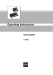
Operating Instructions Zone 2 Ex n Field Device Coupler > 9410/34 Contents 1 Contents 1 2 3 4 5 6 7 8 9 10 11 12 13 2 Contents ................................................................................................................2 General Information ...............................................................................................2 General Safety Instructions ...................................................................................2 Intended Field of Application .................................................................................4 Technical Data ......................................................................................................5 Description of Function ..........................................................................................8 Device Design .......................................................................................................9 Transport, Storage and Disposal ...........................................................................9 Assemby ..............................................................................................................10 Installation ...........................................................................................................10 Putting into Service .............................................................................................15 Maintenance ........................................................................................................17 EC Declaration Of Conformity .............................................................................18 General Information 2.1 Manufacturer R. STAHL Schaltgeräte GmbH Am Bahnhof 30 74638 Waldenburg Germany Phone: +49 7942 943-0 Fax: +49 7942 943-4333 Internet: www.stahl-ex.com 2.2 Operating Instructions Information ID-No.: Publication Code: Subject to alterations. 3 209295 / 941060310010 2013-07-24·BA00·III·en·01 General Safety Instructions 3.1 Safety Instructions for Assembly and Operating Personnel The operating instructions contain basic safety instructions which are to be observed during installation, operation and maintenance. Non-observance will endanger persons, plant and the environment. WARNING Risk due to unauthorised work being performed on the device! Risk of injury and damage to equipment. Assembling, installation, putting into service, operation and maintenance must only be performed by personnel both authorised and suitably trained for this purpose. 2 Zone 2 Ex n Field Device Coupler 9410/34 209295 / 941060310010 2013-07-24·BA00·III·en·01 General Safety Instructions When installing the devices: X When using the device in Zone 2, the device must be built into an enclosure which corresponds at least to the requirements of IEC/EN 60079-15. X The connection components (e.g. cable entries, switches, displays, etc.) of the enclosure must comply with the requirements of IEC/EN 60079-15. X Make sure that the maximum permissible ambient temperatures for the enclosure are not exceeded. Before assembly/putting into service: Read through the operating instructions. Give adequate training to the assembly and operating personnel. Ensure that the contents of the operating instructions are fully understood by the personnel in charge. The national assembly and installation regulations (e.g. IEC/EN 60079-14) apply. When operating the devices: Ensure the operating instructions are made available on location at all times. Observe safety instructions. Observe national safety instructions and accident prevention regulations. Operate the device according to its performance data only. Servicing/maintenance or repair work which are not described in the operating instructions must not be performed without prior agreement with the manufacturer. Any damage can invalidate the explosion protection. Any alterations and modifications to the device impairing its explosion protection are not permitted. Install and use the device only if it is undamaged, dry and clean. If you have questions: Contact the manufacturer. 3.2 Warnings Warnings are sub-divided in these operating instructions according to the following scheme: WARNING Type and source of the danger! Possible consequences. Measures for avoiding the danger. They are always identified by the signalling word “WARNING“ and sometimes also have a symbol which is specific to the danger involved. 209295 / 941060310010 2013-07-24·BA00·III·en·01 Zone 2 Ex n Field Device Coupler 9410/34 3 Intended Field of Application 3.3 Symbols Used X Action request: Describes actions to be carried out by the user. Reaction sign: Describes the results or the reactions to the actions taken. Bullet Information sign: Describes notes and recommendations. Warning symbol; danger due to energised parts! Warning symbol: danger due to explosive atmosphere! 4 Intended Field of Application WARNING Use the device in accordance with its designated use only! Otherwise, the manufacturer’s liability and warranty will expire. The device may only be used according to the operating conditions described in these operating instructions. The device must be used in areas subject to explosion hazards only according to these operating instructions. The Field Device Coupler 9410/34-...-30 has four spurs. The Field Device Coupler 9410/34-...-40 has eight spurs. The Field device Coupler 9410/34-...-60 has twelve spurs. The device couplers of the Series 9410/34 are suitable for use in the hazardous area of Zone 2. They are used to connect four, eight or twelve "Ex nA" / "Ex nL" or "Ex ic" field devices or "Ex d", "Ex m" or "Ex q" Zone 1 field devices to a non-intrinsically safe high-energy trunk. Designated use X For all fieldbuses with an IEC 61158-2 physical layer, e.g. Foundation Fieldbus H1 and Profibus PA. X When installed in Zone 2, the trunk connections comply with type of protection "Ex nA". X When operating fieldbus devices of type of protection "Ex nA", the spurs also comply with type of protection "Ex nA". X When operating fieldbus devices of type of protection "Ex nL" or "Ex ic", the trunk must be supplied, according to IEC/EN 60079-11, with "Ex ic voltage limiter", e.g. via the R. STAHL fieldbus power supply 9412/01 or 9412/02). 4 Zone 2 Ex n Field Device Coupler 9410/34 209295 / 941060310010 2013-07-24·BA00·III·en·01 Technical Data Overview of explosion protection for field device couplers, trunks and spurs Zone 2 Ex n Field Device Coupler Zone 0 Zone 1 Zone 2 Non-hazardous area 9410/34-330-30, 9410/34-330-40, 9410/34-330-60 without enclosure not permitted not permitted Enclosure as per IEC 60079-15 required o.k. Trunk not permitted not permitted Ex nA o.k. Spurs and field devices not permitted Ex d / Ex m / Ex q Ex nA / Ex ic / Ex nl or Ex d / Ex m / Ex q o.k. 5 The R. STAHL enclosures Series 8146 (polyester), 8125 (sheet steel or stainless steel), 8126 (stainless steel) and 8150 (stainless steel) meet the requirements indicated above. Technical Data Marking IECEx Ex nA [ic] IIC T4 Gc Europe (ATEX) E II 3 G Ex nA [ic] IIC T4 Gc Certificates IECEx IECEx BVS 11.0015X Europe (ATEX) BVS 11 ATEX E 031 X Installation in Zone 2 and in the safe area Safety data (CENELEC) per spur Max. voltage U0 Uo from connected fieldbus power supply Max. current I0 54 mA (rectangular characteristic) Max. output power Po = 1.35 W (decreases at Ui < 25 V acc. P = U * I) Internal capacitance Ci = 110 pF Internal inductance Li = 0 mH Max. external capacitance Co = 80 nF (for IIC) Max. external inductance Lo = 0,27 mH (for IIC) Data transmission between trunk and spurs passive, no repeater function Trunk, not intrinsically safe / Ex nA Connections 2 trunk connections (A, B), internally bridged Minimum input voltage 10.3 V acc. to FF-846 Voltage range 9 ... 32 V Undervoltage monitoring U < 9 V, spurs deenergized LED "PWR" = OFF Surge protection yes Note: this guarantees an output voltage (spurs) at full load of min. 9.3 V 9 ... 25 V when used with spurs "Ex ic" 9410/34-...-30 9410/34-...-40 9410/34-...-60 (4 spurs) (8 spurs) (12 spurs) Max. current consumption 209295 / 941060310010 2013-07-24·BA00·III·en·01 0 mA each spur 25 mA 25 mA 25 mA 20 mA each spur 105 mA 185 mA 265 mA 41 mA each spur 189 mA 353 mA 517 mA 3 / 7 / 11 spurs at 41 mA, 1 spur in short-circuit 198 mA 362 mA 526 mA Short-circuit all spurs 75 mA 75 mA 75 mA Zone 2 Ex n Field Device Coupler 9410/34 5 Technical Data Trunk, not intrinsically safe / Ex nA Power management When the trunk voltage exceeds 9 V the spurs are energized one after the other to avoid high starting current resulting from field devices. A short circuit detected on a spur will deenergize the respective spur until the short-circuit is removed. Regardless how many spurs are short-circuited the trunk is loaded with max one spur short-circuit current. Thus the trunk current and the device power dissipation are minimized under all conditions. Max. power dissipation 1.2 W Indication LED green „PWR“ (U ) 9 V from trunk) Reverse polarity protection yes Rated operational current (2A Voltage drop trunk A / trunk B ( 10 mV at 2 A / 25 °C Terminating resistor extern (e.g. R. STAHL Type 9418) Spurs, Ex ic / nA / nL Note Spur ic and nL in combination with voltage limited fieldbus power supply only (e.g. R. STAHL Types 9412/01 or 9412/02) Quantity 4, 8, 12 Number of field devices per spur 1 Max. cable length 120 m Voltage drop trunk / spur (1V Current range 0 ... 41 mA per spur Max. short-circuit current 50 mA Earthing of cable shields (trunk and spurs) Connecting over FDC to terminals "S", connected to trunk and spurs, optionally to earthing bar, see accessories and spare parts set earthing bar 4 K or 8 K Fault detection Spur short-circuit 50 mA Indication of short-circuit per spur LED red "SPUR 1" ... "SPUR 12": ON Ambient conditions Ambient temperature - 40 ... + 75 °C Storage temperature - 40 ... + 80 °C Relative humidity (no condensation) < 95 % Electromagnetic compatibility Tested to the following standards and regulations: EN 61326 (IEC/EN 61000-4-1...6 and 11; EN 55022 class B); NAMUR NE 21 (IEC/EN 61000-4-1...6, 8 and 11; EN 55022 class B) Mechanical Data Terminals 3-pole (+, -, screen) Screw terminals trunk / spurs rigid 0.2 ... 2.5 mm2 flexible 0.2 ... 2.5 mm2 flexible, end covering sleeves 0.25 ... 2.5 mm2 Assembly on DIN rail, EN 50022 (NS 35/15, NS 35/7.5) or mounting plate Installation position vertical or horizontal Degree of protection Enclosure IP30 Terminals IP20 Fire protection class (UL-94) 6 V0 Zone 2 Ex n Field Device Coupler 9410/34 209295 / 941060310010 2013-07-24·BA00·III·en·01 Technical Data Installation conditions Connection diagram Foundation Fieldbus H1 or Profibus PA field devices SPUR 1 S ic/nL/nA + SPUR 2 S ic/nL/nA + SPUR 3 S ic/nL/nA + SPUR 4 / 8 / 1 2 S ic/nL/nA + TRUNK A S - nA + I I Foundation Fieldbus H1 or Profibus PA Trunk I TRUNK B S - nA + I Power-Management 14364E02 Dimensional Drawings (All Dimensions in mm / inch) - Subject to Alterations 101 mm / 3.98" 92 mm / 3.62" 64 mm / 2.52" 92 mm / 3.62" 64 mm / 2.52" 57 mm / 2.24" 64 mm / 2.52" 72 mm / 2.83" 153 mm / 6.02" 57 mm / 2.24" 64 mm / 2.52" 72 mm / 2.83" 14361E00 9410/34-330-30 Field device coupler, 4 spurs 14362E00 9410/34-330-40 Field device coupler, 8 spurs 92 mm / 3.62" 64 mm / 2.52" 205 mm / 8.07" 57 mm / 2.24" 64 mm / 2.52" 72 mm / 2.83" 14363E00 9410/34-330-60 Field device coupler, 12 spurs 209295 / 941060310010 2013-07-24·BA00·III·en·01 Zone 2 Ex n Field Device Coupler 9410/34 7 Description of Function 6 Description of Function The field device coupler is used to connect up to four, eight or twelve non-intrinsically safe, non-sparking (nA) or intrinsically-safe (ic) or energy-limited (nL) field devices to a non-intrinsically safe trunk. If intrinsically safe spurs (ic) or energy-limited spurs (nL) are used, a fieldbus power supply which supplies the trunk with limited voltage complying according to type of protection "Ex ic", according to DIN EN 60079-11, must be connected upstream (see chapter "Installation"). The field device coupler works on the physical level, i.e., it works independently of the protocol used. It can therefore be used for any fieldbus which complies with IEC 61158-2. At the moment, these are the Foundation Fieldbus H1 and the Profibus PA. Each field device can be supplied with a maximum current of 41 mA. As short-circuit protection, each spur is equipped with a functional current limiting to 50 mA. If the field device coupler is operated as the last device on the trunk, it must be terminated standard-compliant with a terminating resistor (e.g. R. STAHL type 9418) (see also chapter "Installation"). The trunk voltage connected to the field device coupler is monitored for undervoltage (< 9 V) and indicated by an LED. Other LEDs indicate the status of the spurs. Fieldbus Power Supply Host Zone 2 Trunk Ex nA Spur Field Device Coupler Zone 2 Field Device Coupler Zone 2 Terminator Power Spurs Ex ic / nA Field devices 14454E01 Power management As soon as the voltage of 9 V on the trunk is exceeded , the spurs are activated one after the other to prevent a high start-up current caused by the field devices. In the event of a short-circuit, the spur in question is deactivated until the short-circuit is eliminated. If several spurs are affected by a short-circuit, the trunk is loaded only with one short- circuit current. This minimises the current consumption of the trunk and the power dissipation of the field device coupler under all operating conditions. 8 Zone 2 Ex n Field Device Coupler 9410/34 209295 / 941060310010 2013-07-24·BA00·III·en·01 Device Design 7 Device Design 14458E00 1 2 3 4 8 Detachable terminals for spur 1 ... spur 4, spur 1 ... spur 8 or spur 1 ... spur 12 Terminals for trunks A and B TRUNK A: connection for incoming trunk TRUNK B: connection for outgoing trunk or external terminator Error indication LEDs for spur 1 ... spur 4, spur 1 ... spur 8 or spur 1 ... spur 12 Operation indication LED PWR (Power) Transport, Storage and Disposal Transport Shock-free in its original carton, do not drop, handle carefully. Storage Store in a dry place in its original packaging. Permitted temperature range for storage in original packaging: - 40 °C ... + 80 °C Disposal Ensure environmentally friendly disposal of all components according to the legal regulations. 209295 / 941060310010 2013-07-24·BA00·III·en·01 Zone 2 Ex n Field Device Coupler 9410/34 9 Assemby 9 Assemby WARNING Incorrectly installed components! If the components are installed incorrectly, explosion protection is no longer guaranteed. Carry out assembly strictly according to the instructions and national safety and accident prevention regulations (e.g. IEC/EN 60079-14). Do not select a mounting location that requires a cable length exceeding the maximum permissible value (see chapter "Cable lengths for trunk and spurs"). 9.1 Assembly with Enclosure For installation in Zone 2, enclosures suitable for Zone 2 are available. 9.2 Assembly without Enclosure Field device couplers without enclosures are always delivered ready for DIN rail mounting. X For installation in non-hazardous areas, e.g. in normal control cabinet or open rack. X For assembly in an appropriate enclosure not mentioned above. 10 Installation WARNING Incorrectly installed components! Explosion protection cannot be guaranteed any more if the components are installed incorrectly. Carry out the installation in strict accordance with the instructions and national safety and accident prevention regulations (e.g. IEC/EN 60079-14). 10.1 Engineering Engineering in type of protection "Ex nA" or "Ex ic / nL" 10 When operating fieldbus devices of type of protection "Ex ic" (acc. to IEC 60079-11), "Ex nL" (acc. to IEC 60079-15 until 2010) or "ic-FISCO" (acc. to IEC 60079-27 and IEC 60079-11), the required intrinsically safe current limiting Io is guaranteed by the field device coupler. The voltage limiting required in each case Uo (depending on Ui of the fieldbus device to be connected) is done by selecting a suitable, ic/nL voltage limited fieldbus power supply: for fieldbus devices according to ic-FISCO: Ui > 17.5 V ¡ Uo < 17.5 V = R. STAHL fieldbus power supply 9412/01 for fieldbus devices according to ic / nL: e.g. Ui > 24 V ¡ Uo < 24 V = R. STAHL fieldbus power supply 9412/02 Zone 2 Ex n Field Device Coupler 9410/34 209295 / 941060310010 2013-07-24·BA00·III·en·01 Installation Engineering in explosion-proof type of protection nA or ic (nL) nA Fieldbus power supply Host nL Fieldbus power supply U0 , FPS ≤ 32 V Host UO ≤ 25 V Trunk lenght 1 Trunk lenght 1 Spur Spur Trunk, Trunk, Ex nA Field device coupler Zone 2 Ex nA Field device coupler Zone 2 Ui UN Host redundant Host redundant Uo =Ui ≤ 25 V UN ≤ UN, FPS ≤ 32 V 12698E01 Engineering example 1 Fieldbus segment with "daisy chain structure". The trunk is looped through the field device couplers. Fieldbus Power Supply Trunk length 1 Trunk length 2 Field Device Coupler Zone 2 Trunk length 3 Field Device Coupler Zone 2 Trunk length 4 Field Device Coupler Zone 2 Field Device Coupler Zone 2 length Spurs Ex nA / ic 14455E01 Engineering example 2 Fieldbus segment in which the field device couplers are connected to the trunk with junction boxes (T-connectors). Fieldbus Power Supply Length 1 Field Device Coupler Length 2 Length 3 Field Device Coupler Field Device Coupler Length 4 Field Device Coupler Length A ic 14456E01 209295 / 941060310010 2013-07-24·BA00·III·en·01 Zone 2 Ex n Field Device Coupler 9410/34 11 Installation Engineering example 3 Fieldbus segment with star structure. Fieldbus power supply Host Trunk lenght 2 Trunk lenght 1 Spur Trunk, Ex nA <= 1 m <= 1 m <= 1 m Field Device Coupler Zone 2 Host redundant Field Device Coupler Zone 2 Field Device Coupler Zone 2 Field Device Coupler Zone 2 Spur lenght Spurs Ex nA / ic 14458 7E01 10.2 Cable Lengths for Trunk and Spurs in Accordance with IEC 61158-2, Annex B (without Considering the Explosion Protection) The maximum length of all cables (all trunks, all spurs) per segment must not exceed 1900 m. For engineering, use the Fieldbus Wizard Engineering Tool. Download available at www.fieldbus-solutions.info Max. cable length for spurs, 1 field device per spur Max. cable length when a redundant host is used Number of all field devices on the segment, including host(s) 1 ... 12 13 ... 14 15 ... 18 19 ... 24 25 ... 30 120 m 90 m 60 m 30 m 1m 90 m 60 m 30 m 1m 1m The actual trunk and spur lengths can be shorter due to voltage drop. The following generally applies: Spurs should be kept as short as possible. 10.3 Examples of Cable Lengths Cable lengths for trunk with 12 field devices at a current consumption of 15 mA each: For engineering, use the Fieldbus Wizard Engineering Tool. Download available at www.fieldbus-solutions.info Assumption: X X X X 12 Fieldbus power supply with Uout > 25 V / Iout > 350 mA. Current consumption of host is 20 mA. Type A fieldbus cables (loop resistance: 48 Ohm/1000 m) are used. Three field device couplers are located at the end of the trunk. Maximum trunk length: approx. 1000 m Zone 2 Ex n Field Device Coupler 9410/34 209295 / 941060310010 2013-07-24·BA00·III·en·01 Installation Cable lengths for trunk with 16 field devices at a current consumption of 15 mA each: Assumption: X Fieldbus power supply with Uout > 25 V / Iout > 350 mA. X Current consumption of host is 20 mA. X Type A fieldbus cables (loop resistance: 48 Ohm/1000 m) are used. X Four field device couplers are located at the end of the trunk. Maximum trunk length: approx. 800 m 10.4 Connection WARNING Danger due to live parts! Explosion protection is not guaranteed any longer. Before carrying out work on the trunk, the fieldbus must be disconnected from the supply. Secure the fieldbus against unauthorised activation. EXCEPTION: For spurs which comply with type of protection "ic" or "nL", work on live parts is permissible. The screw terminals for trunk and spurs are detachable. This facilitates the connection of cables on the terminals. Foundation Fieldbus H1 or Profibus PA field devices SPUR 1 S ic/nL/nA + SPUR 2 S ic/nL/nA + SPUR 3 S ic/nL/nA + SPUR 4 / 8 / 1 2 S ic/nL/nA + TRUNK A S - nA + I I Foundation Fieldbus H1 or Profibus PA Trunk I TRUNK B S - nA + I Power-Management 14364E00 1 SPUR 3 S - + SPUR 2 SPUR 9 S - + S - + S - + SPUR 10 SPUR 11 SPUR 12 SPUR 4 SPUR 5 SPUR 6 + SPUR 1 + - SPUR 8 - S SPUR 7 S + + - - S S + + - - S S 2 PWR TRUNK B TRUNK A FIELD DEVICE COUPLER ZONE 2 Ex n 9410/34-330-60 S - + S - + 11182E00 209295 / 941060310010 2013-07-24·BA00·III·en·01 Zone 2 Ex n Field Device Coupler 9410/34 13 Installation Trunk TRUNK A and TRUNK B (+,-,S) are connected to each other in terminal "TRUNK A / TRUNK B". Disconnect the fieldbus from the power supply. Open the enclosure, if necessary. Insert the cables in the corresponding terminals of terminal "TRUNK A / TRUNK B" (2): TRUNK A: cable from the host or the fieldbus power supply TRUNK B: if required, cable to the next field device coupler or terminator (if it is the last device on the trunk) Close/tighten the terminals. Close the enclosure, if necessary. Spurs Only one field device may be connected on each spur connection. For spurs wich comply with type of protection "ic" or "nL", work on live parts is permissible. Disconnect the fieldbus from the power supply. Open the enclosure, if necessary. Insert the cables in the corresponding terminals of the detachable terminals "SPUR 1" ... "SPUR X" (1): Close/tighten the terminals. Plug the detachable terminals on the terminal block and secure them with safety screws against loosening. Close the enclosure, if necessary. 10.5 Earthing Field device coupler without enclosure The field device coupler does not have to be connected to earth. The screens of trunk A, trunk B and the spurs are internally connected via terminals "S". Field device coupler with metallic enclosure Connect the enclosure to earth via the shortest possible distance. 10.6 Earthing of Cable Shields There are different regulations regarding earthing of cable shields: X IEC / EN 60079-14, section 12.2.2.3 X Profibus Technical Guideline "Profibus PA" User and Installation Guideline, section 3.3.3 X Fieldbus Foundation "System Engineering Guidelines" AG 181, rev. 3.1, chapter 7.3, section 6.2f 14 Zone 2 Ex n Field Device Coupler 9410/34 209295 / 941060310010 2013-07-24·BA00·III·en·01 Putting into Service 10.7 Terminating Resistor (terminator) A terminating resistor is required at both ends of the trunk. Spurs are operated without terminating resistors. The field device coupler is located at the end of the trunk T (termination with external terminating resistor) SPUR 7 SPUR 8 SPUR 9 SPUR 10 SPUR 11 SPUR 12 SPUR 5 SPUR 6 14460E00 Connect the external terminating resistor 9418 to the terminals "TRUNK B +" and "TRUNK B -". The external terminating resistor is active. 11 Putting into Service Before putting into service Test the components for correct operation and installation in accordance with the operating instructions and other applicable specifications. Check whether cables and lines are clamped properly. Inspect enclosure for damage. Inspect enclosure for foreign bodies. Check whether all unused cable glands and holes are sealed off properly. The voltage on the trunk must be at least 9 V DC. The voltage on the connected field devices must be at least 9 V DC. Putting into Service Observe the national regulations when putting into service. Observe the directives in accordance with IEC/EN 60079-17 when performing functional checks. 209295 / 941060310010 2013-07-24·BA00·III·en·01 Zone 2 Ex n Field Device Coupler 9410/34 15 Putting into Service LED displays, description of function SPUR 7 SPUR 8 SPUR 9 SPUR 10 SPUR 11 SPUR 12 SPUR 5 SPUR 6 14459E00 PWR, SPUR 1 ... SPUR 4, Description green SPUR 1 ... SPUR 8 or SPUR 1 ... SPUR 12, red Off Off No voltage on the trunk On Off Normal mode: Corresponding spur connected to field device, 0 mA ( I ( 40 mA On 16 Zone 2 Ex n Field Device Coupler 9410/34 In case of error: Voltage on the trunk o.k. U)9V Open-circuit on the corresponding spur Spur not connected Short-circuit on the corresponding spur 50 mA 209295 / 941060310010 2013-07-24·BA00·III·en·01 Maintenance 12 Maintenance 12.1 Regular maintenance work WARNING Danger due to live parts! Explosion protection is not guaranteed any longer. Before carrying out work on the trunk, the fieldbus must be disconnected from the supply. Secure the fieldbus against unauthorised activation. EXCEPTION: For spurs which comply with type of protection "ic" or "nL", work on live parts is permissible. Consult the relevant national regulations (e.g. IEC/EN 60079-17) to determine the type and extent of inspections. Plan the intervals so that any defects in the equipment which may be anticipated are promptly detected. To check as part of the maintenance schedule: X X X X X X X X Check if the cables are clamped properly. Check if safety screws of the plug-in terminals are tightened properly. Inspect tightness of the cable glands. Inspect the enclosure for visual damage. Check the seal between enclosure and cover. Check the enclosure for moisture. Check for compliance with the permissible temperatures. Make sure that the device is used according to its designated use. 12.2 Repair work WARNING Danger due to improper maintenance/repairs Explosion protection is not guaranteed any longer. Repair work to the device must only be performed by R. STAHL. 12.3 Cleaning X Clean with a cloth, brush, vacuum cleaner or similar items. X When cleaning with a damp cloth, use water or mild, non-abrasive, non-scratching cleaning agents. X Never use aggressive cleaning agents or solvents. 209295 / 941060310010 2013-07-24·BA00·III·en·01 Zone 2 Ex n Field Device Coupler 9410/34 17 EC Declaration Of Conformity 13 EC Declaration Of Conformity 18 Zone 2 Ex n Field Device Coupler 9410/34 209295 / 941060310010 2013-07-24·BA00·III·en·01