1
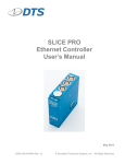
SLICE PRO Timed Output Module User’s Manual November 2015 13000-30730-MAN (Rev. 0) © Diversified Technical Systems, Inc. - All Rights Reserved SLICE PRO TOM User’s Manual November 2015 Table of Contents DTS Support ....................................................................................................................... 4 Connector Panel ................................................................................................................. 5 Squib Channels (1-4).......................................................................................................... 6 DC Capacitive Discharge ................................................................................................. 6 DC Constant Current ....................................................................................................... 6 Squib Resistance Test ..................................................................................................... 7 Electronic Identification (EID) ........................................................................................... 7 Squib LEDs (1 per channel) ............................................................................................. 7 ARM Enable ........................................................................................................................ 7 DIGITAL OUT (8 channels) ................................................................................................ 8 Alarm Output .................................................................................................................... 8 UP/DOWN Interface Connectors ....................................................................................... 8 Timing Functions ............................................................................................................... 9 Status (STS) and Power (PWR) LEDs ............................................................................. 10 Basic Care and Handling ................................................................................................. 11 Safety Protocol............................................................................................................... 11 Shock Rating.................................................................................................................. 11 Mounting Considerations ........................................................................................... 12 Thermal Considerations ................................................................................................. 12 Power Management.......................................................................................................... 13 Power Consumption ....................................................................................................... 13 Internal Battery............................................................................................................... 13 Power-up and Power-down Procedures ........................................................................ 13 Communication Features ................................................................................................ 14 Appendix A: SLICE PRO TOM Connector Pin Assignments ........................................ 15 Suggested Connector Sources ...................................................................................... 16 Appendix B: UP/DOWN Connector Information ........................................................... 17 Appendix C: Mechanical Specifications........................................................................ 18 Accessories/Support Equipment: ................................................................................... 19 support.dtsweb.com ii 13000-30730-MAN (Rev. 0) SLICE PRO TOM User’s Manual November 2015 Appendix D: Constant Current Mode [approximate time (ms) in regulation] ............ 20 Appendix E: Digital Output Drive Strength ................................................................... 21 Appendix F: Alarm Output Drive Strength .................................................................... 22 support.dtsweb.com iii 13000-30730-MAN (Rev. 0) SLICE PRO TOM User’s Manual November 2015 DTS Support SLICE PRO systems are designed to be reliable and simple to operate. Should you need assistance, DTS has support engineers worldwide with extensive product knowledge and crash test experience to help via telephone, e-mail or on-site visits. The best way to contact a DTS support engineer is to submit a request through the DTS Help Center web portal (support.dtsweb.com). You must be registered (support.dtsweb.com/registration) to submit a request (https://support.dtsweb.com/hc/enus/requests/new). Registration also enables access to additional self-help resources and non-public support information. This manual supports the following products: 13000-30730: SLICE PRO TOM (Timed Output Module) support.dtsweb.com 4 13000-30730-MAN (Rev. 0) SLICE PRO TOM User’s Manual November 2015 Introducing the SLICE PRO TOM Each SLICE PRO Timed Output Module (TOM) is a self-contained system with 12 independently-programmable timing channels. Four channels have programmable drivers for firing pyrotechnic initiators (hereinafter referred to as squib) common to air bags and safety belt pre-tensioning devices. There are also 8, fully-isolated, digital output channels that may be used to generate switch closure or 5 V TTL logic signals for devices such as cameras, strobes, braking systems, etc. TOMs may be used side-by-side with other SLICE PRO modules including Sensor Input Modules (SIMs) and the Trigger Distributor (TDM). Shock hardened to 100 g for dynamic testing environments. 4 completely independent energy delivery channels that can fire air bag squibs or other pyrotechnic devices via capacitive discharge or constant current; wired identically to TDAS PRO TOM. 8 digital output channels; wired identically to TDAS PRO TOM. Alarm output. Internal battery with up to 1 hour capacity functions as primary or back-up power. LED indicators for power, system status and squib channel status. Easy communications via the SLICE PRO USB Controller or Ethernet Controller. Chainable with up to three other SLICE PRO modules. Connector information and pin assignments can be found in Appendices A and B. Mechanical specifications are included in Appendix C. Please see your packing list for your hardware’s specifications. Connector Panel The connector panel provides access to all squib channels (4), LED indicators, arm enable, digital output channels (8) and alarm output. support.dtsweb.com 5 13000-30730-MAN (Rev. 0) SLICE PRO TOM User’s Manual November 2015 Squib Channels (1-4) Each TOM contains 4 independent squib driver channels that support both capacitive discharge and constant current. Each channel may be configured individually via software. When the system is armed, the energy storage capacitor in each programmed channel charges to ~17 V. Current and voltage are automatically recorded for all programmed squib channels. Current is recorded via a dedicated current shunt and amplifier that converts the current into an accurate voltage. Two voltage-recording options are available under software control; you may either record the output voltage to the squib (Record Voltage) or record the timer drive signal (Record Initiation). CAUTION: DTS does not recommend using level trigger for any testing that includes the SLICE PRO TOM. DC Capacitive Discharge The charged capacitor is connected to the output connector through a low resistance, solidstate switch at the pre-programmed time. Typical peak output currents are ~7 A with a 2 ohm load. DC Constant Current The charged capacitor is connected to the output connector through a switching regulator. Active feedback is used regulate the output current to the programmed value. Current may be set between 1.0 A and 4.0 A in 0.1 A steps. The duration that each TOM channel will be able to deliver the selected current is dependent upon the resistance of the connected load and the current setting. The table below provides the typical maximum pulse width at the set current for a few common settings. A detailed graph is provided in Appendix D. Current Setting With 2 ohm Load With 1 ohm Load 1.0 A 44.0 ms 48.0 ms 2.0 A 17.5 ms 22.0 ms 3.0 A 9.2 ms 12.8 ms 4.0 A 4.8 ms 8.0 ms support.dtsweb.com 6 13000-30730-MAN (Rev. 0) SLICE PRO TOM User’s Manual November 2015 Squib Resistance Test Each squib channel contains a resistance measurement circuit that measures the voltage drop across any connected load resulting from a 1 mA current source. The useful measurement range is 0.2 to 9.5 ohms. The software records the connected squib resistance to within about 0.1 ohm accuracy during the set-up routine prior to arming. Once the system is armed, the squib resistance of all programmed channels is constantly monitored. If any channel’s resistance falls outside of the user-programmed limits for that channel, the TOM will generate a system fault and the test can be aborted if desired. Electronic Identification (EID) Each squib channel supports communication with silicon serial number devices manufactured by Dallas Semiconductor/Maxim Integrated Products. When an ID chip is connected to the proper pins on the squib connector, the software can read these devices and correlate the serial number to channel set-up information stored in the sensor database. Squib LEDs (1 per channel) Pre-Test Post-Test Channel armed (squib energized); squib within resistance tolerance limits System fault; channel armed (squib energized) but squib resistance out of tolerance; test may proceed CAUTION – channel triggered but squib still showing continuity (no USB comm) Channel triggered (squib fired); squib now open (no USB comm) Channel not armed; module idle; USB comm active Channel not armed; module idle ARM Enable One of the safety features in the SLICE PRO TOM is that it must be hardware enabled to arm and fire the 4 squib channels. DTS provides an Arm Enable Plug (P/N 13000-30950) with each SLICE PRO TOM that is used for this purpose. Please use caution and care when setting up and arming your unit. ARM Enable Plug (P/N 13000-30950) support.dtsweb.com 7 13000-30730-MAN (Rev. 0) SLICE PRO TOM User’s Manual November 2015 DIGITAL OUT (8 channels) Each TOM contains 8 independent and fully isolated digital output channels. (All –Digital Outputs must be within 24 V of ground.) Each digital channel may be configured individually via software for contact closure (normally open or normally closed) or 5 V TTL logic mode signals. (See Appendix E for digital output drive strength.) In either mode, these channels are not powered and remain in a high-impedance state whenever the module is idle, not armed or the data collection time window has passed. If a device requires a certain signal level when the TOM is not powered, you may have to use pull-up or pull-down resistors as appropriate. If it is necessary to control larger loads or you have questions about your specific application, please contact DTS. Alarm Output An alarm output is also available on the DIGITAL OUT connector. It can be used to turn on a high-visibility, facility warning device to alert technicians of the potential safety hazards of armed/live pyrotechnic devices. Whenever the internal squib voltage source is energized or the module is armed, this output goes high. See Appendix F for a graph showing the alarm output drive strength (voltage vs. output current). WARNING: DTS STRONGY RECOMMENDS all TOM users implement an appropriate high-visibility warning system and safety protocol to keep people away from potentially dangerous devices, such as air bags. UP/DOWN Interface Connectors The UP interface connector allows the unit to interface to a SLICE PRO Ethernet Controller, USB Controller or another SLICE PRO module. The DOWN interface connector allows the unit to interface to another SLICE PRO module. See Appendix B for pin assignments. support.dtsweb.com 8 13000-30730-MAN (Rev. 0) SLICE PRO TOM User’s Manual November 2015 Timing Functions Each TOM has a total of 12 timing channels which are programmable in 0.1 ms increments. There are 2 time-related software settings for each channel: DELAY and DURATION. DELAY is the interval between the event signal and the beginning of the output pulse (i.e., a switch closure at impact or T=0). This interval can be set independently for each channel from 0.25 ms (hardware limitation) to 99,000 ms (99 seconds). DURATION is the time window during which the output signal will be active. This interval begins at the end of the delay period. By checking the “Limit Duration” box in the software, the duration parameter may be set independently from 0.2 to 25.5 ms for each of the four squib driver channels. (If the “Limit Duration” box is not checked, the output driver will turn on and stay on for 40 ms or the length of the test, whichever is less.) Additionally, digital output duration can be set independently between 0.2 ms and 1600.0 ms for each channel. In either case, all channels may be active only during the pre-programmed data collection time window. This means that the post-event data collection duration must be greater than the longest duration output event on any squib or digital output channel. support.dtsweb.com 9 13000-30730-MAN (Rev. 0) SLICE PRO TOM User’s Manual November 2015 Status (STS) and Power (PWR) LEDs The SLICE PRO TOM has 2 LEDs that provide power and system status. At system power up, the red-green-blue LED initialization sequence is performed by the status LED followed by the power LED. Recorder Mode Circular Buffer Mode Armed and waiting for Start Record signal to begin data collection Start Record signal received and recording data; waiting for Event signal Event signal received –or– fault Event signal received + data collection completed (no USB comm) Armed and recording data; waiting for Event signal Event signal received –or– fault Event signal received + data collection completed (no USB comm) Fault received + data collection completed (no USB comm) Fault received + data collection completed (no USB comm) Data collection completed; PC downloading data Data collection completed; PC downloading data Condition Charging (system off and connected to external power) Unit is charging (power OK) Unit fully charged System on; not armed ... Power up Power OK; no USB comm Power OK; USB connected Power fault (out of range) Communicating with host support.dtsweb.com 10 13000-30730-MAN (Rev. 0) SLICE PRO TOM User’s Manual November 2015 Basic Care and Handling The SLICE PRO systems are precision devices designed to operate reliably in dynamic testing environments. Though resistant to many environmental conditions, care should be taken not to subject the unit to harsh chemicals, submerge it in water, or drop it onto any hard surface. WARNING: Electronic equipment dropped from desk height onto a solid floor may experience as much as 10,000 g. Under these conditions, damage to the exterior and/or interior of the unit is likely. The SLICE PRO TOM is supplied with calibration data from the factory. DTS recommends annual recalibration to ensure that the unit is performing within factory specifications. The SLICE PRO TOM is not user-serviceable and should be returned to the factory for service or repair. When not in use or if shipping is required, we suggest that you always place the unit in the padded carrying case originally provided with your unit. Safety Protocol TOM modules employ a three-tiered safety protocol: 1. The software must receive set-up and arming commands from the user in the correct sequence. 2. The module firmware must load a safety key (bit pattern) into the fire controller. 3. The Arm Enable Plug must be installed. (When the Arm Enable Plug is not installed, the squib outputs are shorted.) WARNING: DTS STRONGY RECOMMENDS all users of TOMs implement an appropriate high-visibility warning system and safety protocol to keep people away from potentially dangerous devices, such as air bags. Shock Rating The SLICE PRO TOM is rated for 100 g, 12 ms half-sine duration, in all axes. support.dtsweb.com 11 13000-30730-MAN (Rev. 0) SLICE PRO TOM User’s Manual November 2015 Mounting Considerations The unit should be securely bolted to the test article or dynamic testing device to provide the best shock protection. Mounting methods and hardware selection should be carefully calculated to withstand expected shock loading and facilitate proper grounding. Check bolt tightness periodically to ensure that 1) the unit is securely fastened to the baseplate, and 2) the baseplate is securely fastened to the testing platform. (See Appendix C for the unit’s mechanical specifications.) Thermal Considerations The SLICE PRO systems are low power devices with negligible self-heating and it is unlikely that self-heating will be an issue in real-world testing. Should there be any questions about using SLICE PRO in your environment, please contact DTS. support.dtsweb.com 12 13000-30730-MAN (Rev. 0) SLICE PRO TOM User’s Manual November 2015 Power Management A good power source is of paramount importance. SLICE PRO TOMs should be powered from a SLICE PRO Controller. (One Controller can support up to 4 SLICE PRO modules.) Be sure to consider any power drop due to cable length. Input Voltage, System OFF/ON Power Consumption, System OFF* Power Consumption, System ON** 11.5-16 VDC; 15 VDC nominal 7.5 W; 500 mA per module*** 12 W; 800 mA per module*** * charging all internal batteries ** fully armed + charging all internal batteries *** Controllers are considered modules for the purposes of power calculations. Power Consumption Power off: When connected to sufficient external power, the SLICE PRO TOM will draw up to 500 mA for charging the internal battery. Power on: When the TOM is initially powered, all excitation circuits, signal conditioning sources, etc., are in a shutdown state. When the user runs a test set-up, the software automatically energizes these circuits. The current draw per TOM will increase to as much as 800 mA when the system is fully armed. During data collection: Once the system has been armed, all circuits remain in a full power state until data collection is finished. After the data collection routine has completed, the TOM de-energizes several circuits to minimize power consumption. Internal Battery The SLICE PRO TOM contains an internal 7.4 V (nominal) lithium battery that operates as primary power or back-up power. If input power fails, the unit will transition to its own internal battery. When fully charged, battery capacity is sufficient to provide primary power and sustain full operation for 1 hour. It charges whenever sufficient external power is connected to the module. The maximum charge time is 3-4 hours from complete discharge to full capacity. The module does not need to be ON in order to charge the internal battery. Charging practices can affect the useful operational life of the battery. In addition to good charging habits, conditioning the battery may be useful—three deep-discharge/recharge cycles may increase battery performance. The battery’s useful capacity is greatly shortened near the end of its service life and should be replaced when it has decreased to 50% of its initial capacity. The battery is not user-serviceable and should be returned to the factory for battery replacement. Power-up and Power-down Procedures The SLICE PRO TOM is powered up when the proper signal is connected at the UP interface connector. This is typically accomplished via a SLICE PRO Controller. Power-up of the module takes 10 seconds (USB Controller) or ~90 seconds (Ethernet Controller), after which communication is enabled. To restart, turn off the system and wait ~30 seconds before reinitializing. If a system is armed for data collection, it will remain on support.dtsweb.com 13 13000-30730-MAN (Rev. 0) SLICE PRO TOM User’s Manual November 2015 until it is disarmed or power reserves are exhausted. An incomplete power-down/power-up cycle can result in errors, so be certain to follow proper procedures. Communication Features Communications with the SLICE PRO TOM is accomplished via 1) a SLICE PRO USB Controller and USB comm cable (USB A to USB B) or 2) a SLICE PRO Ethernet Controller and Ethernet (REC) comm cable (P/N 10700-0015x). Please see the SLICE PRO USB Controller or SLICE PRO Ethernet Controller User’s Manuals for additional information. support.dtsweb.com 14 13000-30730-MAN (Rev. 0) SLICE PRO TOM User’s Manual November 2015 Appendix A: SLICE PRO TOM Connector Pin Assignments 6-pin Squib Output channels 1-4* 19-pin DIGITAL OUT connector* (EEG.2B.306.CLL) (EEA.2B.319.CLL) (panel view) (panel view) Suggested cable connector P/N: FGG.2B.306.CLADxx** Suggested cable connector P/N: FGA.2B.319.CLADxx** Pin Function Pin Function 1 + Squib 1 + Digital out (Ch 1) 2 + Sense 2 - Digital out (Ch 1) 3 + ID 3 + Digital out (Ch 2) 4 - ID 4 - Digital out (Ch 2) 5 - Squib 5 + Digital out (Ch 3) 6 - Sense 6 - Digital out (Ch 3) 3-pin ARM connector 7 + Digital out (Ch 4) (EEG.2B.303.CLL) 8 - Digital out (Ch 4) 9 + Digital out (Ch 5) 10 - Digital out (Ch 5) 11 + Digital out (Ch 6) 12 - Digital out (Ch 6) 13 + Digital out (Ch 7) 14 - Digital out (Ch 7) 15 + Digital out (Ch 8) 16 - Digital out (Ch 8) 17 + Alarm output 18 - Alarm output (panel view) Suggested cable connector P/N: FGG.2B.303.CLADxx** Pin Function 1 Arm enable (short to pin 2) 2 Arm enable (short to pin 1) 3 No connection (do not connect to ground) 19 No connection * wired identically to TDAS PRO TOM ** xx denotes diameter of cable to be used; e.g., 52 = 5.2 mm. See www.lemo.com for more information. support.dtsweb.com 15 13000-30730-MAN (Rev. 0) SLICE PRO TOM User’s Manual November 2015 Suggested Connector Sources DTS uses LEMO connectors on the SLICE PRO TOM. If you need to purchase connectors, we suggest first going to LEMO directly (www.lemo.com). Their web site and worldwide sales team are very helpful. Should you have difficulty obtaining a specific part number, they can suggest connector variations or alternates and explain options that may be useful for your particular application. Another U.S. source is Alpine Electronics (www.alpine-electronics.com) in San Jose, California. They are a stocking distributor for LEMO connectors. support.dtsweb.com 16 13000-30730-MAN (Rev. 0) SLICE PRO TOM User’s Manual November 2015 Appendix B: UP/DOWN Connector Information UP interface connector* (Omnetics A99077-015; MMDS-015-N06-SS) 8 DOWN interface connector (Omnetics A98000-015; MMDP-015-N00-SS) 1 1 15 8 9 9 (panel view) 15 (panel view) Pin Function 1 VDC in (UP)/out (DOWN) 2 VDC in (UP)/out (DOWN) 3 Ground 4 Ground 5 /ON (contact closure input to ground) 6 /EVENT (contact closure input to ground) 7 /START (contact closure input to ground) 8 Status input (UP)/output (DOWN) (5 V via 10k with respect to ground) 9 VDC in (UP)/out (DOWN) 10 VDC in (UP)/out (DOWN) 11 Ground 12 Ground 13 USB_DP 14 USB_DM 15 USB power * The UP connector may appear loose. Do not tighten. support.dtsweb.com 17 13000-30730-MAN (Rev. 0) SLICE PRO TOM User’s Manual November 2015 Appendix C: Mechanical Specifications Weight: ~750 g (26.5 oz) Units in mm (inches) support.dtsweb.com Torque spec: 84 in-lb (M6) 18 13000-30730-MAN (Rev. 0) SLICE PRO TOM User’s Manual November 2015 Accessories/Support Equipment: 10200-00030: 10200-00031: 10200-00040: 10700-00230: 10700-0024x: 12000-00110: 13000-30950: TOM Squib Fire LED Indicator Plug TOM Squib Fire Dummy Load Plug TOM Shorting Plug for Squib Output (TSX) Cable Cable, TOM DIG OUT to TOM terminal box (12000-00110) (150 cm) Cable, TOM squib out to pigtail term (TSX) TOM (Timed Output Module) Terminal Box SLICE PRO TOM Arm Enable Plug (see page 7 for photo) (x = multiple lengths available) Units in inches (mm) 12000-00110: TOM Terminal Box Dimensions support.dtsweb.com 19 13000-30730-MAN (Rev. 0) SLICE PRO TOM User’s Manual November 2015 Current Load (A) Appendix D: Constant Current Mode [approximate time (ms) in regulation] (20% tolerance for energy storage capacitor) ~25 W deviation inclusive of all variations Resistance Load (Ω) support.dtsweb.com 20 13000-30730-MAN (Rev. 0) SLICE PRO TOM User’s Manual November 2015 Output (V) Appendix E: Digital Output Drive Strength Output Current (mA) support.dtsweb.com 21 13000-30730-MAN (Rev. 0) SLICE PRO TOM User’s Manual November 2015 Differential Voltage (V) Appendix F: Alarm Output Drive Strength Output Current (mA) support.dtsweb.com 22 13000-30730-MAN (Rev. 0) SLICE PRO TOM User’s Manual November 2015 Revision History Rev Date By 0 17 Nov 2015 EK support.dtsweb.com Description Initial release. 23 13000-30730-MAN (Rev. 0)