1
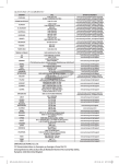
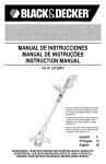
Operating Instructions Read Head CET-AX with Guard Locking and Guard Locking Monitoring
Correct use
Safety precautions
Series CET-AX read heads are operated in combination with an evaluation unit in the system family
CES-AZ. In this combination the read head CET-AX
is an electromagnetic interlock device with guard
locking and guard locking monitoring.
Safety components fulfill personal protection functions. Incorrect installation or tampering can lead to
fatal injuries to personnel.
In combination with a safety guard and the machine
control, this safety system prevents the safety guard
from being opened while a dangerous machine
movement is being performed.
For the control system, this means that
ffstarting commands which cause hazardous situations must become active only when the safety
guard is in protective position and the guard locking is in locked position. The locked position of
the guard locking must be released only when the
hazardous situation is no longer present.
Before safety components are used, a risk assessment must be performed on the machine in
accordance with
ffEN ISO 13849-1, Safety of machinery. Safety related parts of control systems. General principles
for design, Annex B
ffEN ISO 12100, Safety of machinery - General
principles for design - Risk assessment and risk
reduction
ffIEC 62061, Safety of machinery. Functional safety
of safety-related electrical, electronic and programmable electronic control systems.
Correct use includes compliance with the relevant
requirements for installation and operation, in
particular
ffEN ISO 13849-1, Safety of machinery. Safety related parts of control systems. General principles
for design
ffEN 1088, Safety of machinery. Interlocking
devices associated with guards. Principles for
design and selection
ffEN 60204-1, Safety of machinery. Electrical equipment of machines. General requirements.
The read head is only allowed to be operated in
conjunction with the intended EUCHNER CET actuators and the related connection components from
EUCHNER. On the use of different actuators or
other connection components, EUCHNER provides
no warranty for safe function.
The read head CET is only allowed to be used in
combination with a system family CES-AZ evaluation
unit (see Table 2).
ff Version CET2, guard locking by solenoid force
Check the safe function of the safety guard particularly
ffafter any setup work
ffafter the replacement of a system component
ffafter an extended period without use
ffafter every fault
Independent of these checks, the safe function of the
safety guard should be checked at suitable intervals
as part of the maintenance schedule.
Fatal injury due to incorrect connection or incorrect use.
Safety switches must not be bypassed (bridging of contacts), turned away, removed or
otherwise rendered ineffective. On this topic
pay attention in particular to the measures
for reducing the possibility of bypassing from
EN 1088:1995+A2:2008, Section 5.7.
ff
The device may be installed and put into operation only by authorized experts
who are familiar with the correct handling of
safety components
ff
who are familiar with the applicable EMC
regulations
ff
Correct use requires observing the permissible
operating parameters (see Technical data).
If a product data sheet is included with the
product, the information on the data sheet applies in case of discrepancies with the operating
instructions.
ff
The PL that can be achieved depends on the
installation position and the evaluation unit used.
Pay attention to the information in Table 2.
ff
Exclusion of liability and warranty
In case of failure to comply with the conditions for
correct use stated above, or if the safety instructions are not followed, or if any servicing is not
performed as required, liability will be excluded and
the warranty void.
Example: If the risk of accidental locking inside
a safety guard during a power failure is higher
than the risk of ineffective guard locking.
The lift tappet is initially extended by spring force.
The spring force on the guard locking pin is not
sufficient to press down the lift tappet. Only when
the guard locking solenoid is also switched on does
the lift tappet retract. The guard locking is active.
The guard locking operates in accordance with the
open-circuit current principle.
The safety door can be opened as long as the lift tappet is held in the extended position by spring force.
Releases
Important:
The releases are not safety functions.
ff
The machine manufacturer must select and use
a suitable release (escape release, emergency
unlocking, etc.) for a specific application. A risk
assessment appraisal is required for this purpose.
It may be necessary to take specifications from
a product standard into account.
ff
The releases must not be used to lock the switch
during maintenance work to prevent activation of
guard locking, for example.
ff
who have read and understood the operating
instructions and the system manual.
ff
The switching operation must only be triggered by actuators specifically provided for
this purpose (see Table 3) which are positively
connected to the safety guard.
ff
ff
Function
The correct function must be checked at regular
intervals.
Loss of the release function due to mounting
errors or damage during mounting.
Check the release function every time after
mounting.
ff
Loss of the release function due to tension on
the actuator. The door must not be under tension
during release.
ff
In the read head there is a lift tappet (1) that contains
the transponder (see Figure 1). The actuator has a
spring-mounted guard locking pin (2) in which there
is a CES actuator. The guard locking is active if the
lift tappet is retracted and the guard locking pin is
in the recess (3) on the read head.
Actuator
Read head
Observe the notes on the enclosed data sheets.
ff
Mechanical release and mechanical key
release (can be retrofitted)
The mechanical release can be used to unlock guard
locking, irrespective of the state of the solenoid.
Using mechanical release
1. Unscrew locking screw
2. Using a screwdriver, turn the mechanical
release by around 180° in the direction of the
arrow
ff
ff
who are familiar with the applicable regulations on health and safety and accident
prevention
ff
Important:
The user is responsible for the integration of
the device into a safe overall system. For this
purpose, the overall system must be validated,
e.g. according to EN ISO 13849‑2.
The safety guard can be opened immediately in
the event of interruption of the solenoid power
supply! Usage only in special cases in accordance with strict evaluation of the accident risk
(see DIN EN 1088 (1995), Section 5.5)!
Figure 1: Read head and actuator
ff Version CET1, guard locking by spring force
The lift tappet is pressed into the locked position
by the force of the spring for the guard locking pin
in the actuator and unlocked electromagnetically by
the read head. The guard locking functions in accordance with the closed-circuit current principle. The
locked safety guard cannot be opened immediately
in the event of interruption of the power supply to
the solenoid.
The actuator's guard locking pin cannot be moved
out of the recess and the door is locked in the closed
position as long as the lift tappet is pressed down
by the guard locking pin.
When the operating voltage is present at the locking solenoid, the lift tappet is extended and lifts the
actuator's guard locking pin above the edge of the
recess. The safety door can then be opened.
¨¨ The safety device can be opened
The mechanical release must be returned to its
original position and sealed after use (for example
with sealing lacquer).
Using mechanical key release
On devices with mechanical key release (can be
retrofitted), simply turn the key to unlock. For mounting, see the mechanical key release supplement.
Emergency unlocking (can be retrofitted) ¨¨ Guard locking cannot be activated, and it must Changing the approach direction
not be possible to start the machine. Important:
Test this before entering the danger area.
Using emergency unlocking
Important:
The door must not be under tension when emergency unlocking is actuated.
ffTurn emergency unlocking clockwise until it clicks
into place.
¨¨ The safety device can be opened
To reset, press the detent bolt inward using a small
screwdriver or similar tool and turn the emergency
unlocking back.
Escape release (optional)
The escape release is used to open a locked safety
guard from the inside (see dimension drawing in the
section Technical data).
Fit escape release such that operation, inspection
and maintenance are possible.
Using the escape release
ffPress the red release knob to the stop
¨¨ The safety device can be opened
Pull the knob out again to reset.
Wire front release (optional)
The wire front release permits remote release of
the guard locking via a pull rope. Flexible routing of
the pull rope permits release of the guard locking
in inaccessible installation situations.
Lockout mechanism (optional)
Important:
The lockout mechanism is not a safety function.
ff
The correct function must be checked at regular
intervals.
ff
The lockout mechanism can be used to prevent
maintenance personnel from being unintentionally
locked in the danger area, for example.
In locked position, the lockout mechanism prevents
activation of guard locking. The lockout mechanism
can be secured in locking position with up to three
locks. The mechanical release can still be used.
Using the lockout mechanism
Resetting the lockout mechanism:
1. Open the safety door if necessary
2. Remove the lock
3. Move lockout mechanism to basic position
(Figure 1 A)
Mounting
Figure 2: Changing the approach direction
Caution:
Caution:
Risk of damage to equipment as a result of incorrect
installation. Safety switches must not be used as a
mechanical end stop.
Fit an additional end stop for the movable part of
the safety guard.
ff
Protection against environmental effects
A lasting and correct safety function requires that the
actuating head must be protected against foreign
bodies such as swarf, sand, blasting shot, etc.,
which can become lodged in the recess. For this
purpose, the read head should be installed with the
actuating head facing down.
!
Observe the min. door radii (see Figure 3).
Ensure that the actuator contacts the slide in the
designated area (see figure below). Marks on
the slide specify the prescribed approach zone.
ff
Note the following points:
Actuator and safety switch must be easily accessible for inspection and replacement.
ffThe switching operation must only be triggered by
the specific actuator designated for this purpose.
ffActuator and safety switch must be fitted so that
ffthe actuator is positively mounted on the safety
guard, e.g. by using the safety screws included.
ffthey cannot be removed or tampered with using
simple means.
ffthe active faces of the actuator and the safety
switch are parallel to each other (see Figure 3).
ffthe actuator is fully inserted into the switch recess
when the safety guard is closed (see Figure 3).
ff
Deactivate guard locking and open the safety door
before using the lockout mechanism.
Before entering the danger area:
1. Open the door
Cover the actuating head, the actuator and the rating
plate during painting work!
Electrical connection
The read head CET is only allowed to be used in
combination with a suitable EUCHNER connection cable (see Table 1). The connection cable
contains two screened cores for the signal
from the read head. This screening must not be
interrupted on the route to the evaluation unit
or earthed at any other point (see Figure 8).
All the electrical connections must either be
isolated from the mains supply by a safety
transformer according to IEC EN 61558-2-6
with limited output voltage in the event of a
fault (PELV), or by other equivalent isolation
measures.
For use and operation as per the
requirements,
a power supply with the feature "for use in class 2
circuits" must be used. The same requirement applies to the safety outputs.
2. Press button, move lockout mechanism to
locking position (Figure 1 A and B) and secure
with lock (Figure C)
Pushbutton
ff
ff
Important:
Locking function not active
Remove the screws from the read head.
Set the required direction.
ffTighten the screws with a torque of 1.5 Nm.
ff
Safety switches must not be bypassed (bridging
of contacts), turned away, removed or otherwise
rendered ineffective.
ffOn this topic pay attention in particular to the
measures for reducing the possibility of bypassing
according to EN 1088:1995.A2:2008, Sec. 5.7.
Locking function active
Locking function active
and secured
Push button and
align lever
A
B
Fit lock
C
Figure 1: Function of lockout mechanism
EUCHNER GmbH + Co. KG Kohlhammerstraße 16 D-70771 Leinfelden-Echterdingen Tel. +49/711/75 97-0 Fax +49/711/75 33 16 www.euchner.de [email protected]
Subject to technical modifications, no responsibility is accepted for accuracy of this information. © EUCHNER GmbH + Co. KG 098069-16-11/12 (translation of the original operating instructions)
Operating Instructions Read Head CET-AX with Guard Locking and Guard Locking Monitoring
Operating Instructions Read Head CET-AX with Guard Locking and Guard Locking Monitoring
min
0
R80
74,5 ± 4 mm
!
= 90°
min
R30
0
Anfahrbereich/
Approach Zone
Figure 3: Door radii and approach zone
Alternative solutions must comply with the following
requirements:
Service and inspection
Technical data
Warning:
ff Read head
Electrically isolated power supply unit with a max.
open-circuit voltage of 30 V/DC and a limited
current of max. 8 A.
Loss of the safety function because of damage
to the system.
Electrically isolated power supply unit in combination with fuse as per UL248. This fuse should be
designed for max. 3.3 A and should be integrated
into the 30 V DC voltage section.
ff
ff
In order to avoid EMC interference, the physical
environmental and operating conditions at the
installation site of the device must comply with
the requirements according to the standard
EN 60204‑1:2006, section 4.4.2 (EMC).
For terminal assignment see Figure 4.
ffFor detailed information see the system manual
for the evaluation unit used.
ff
Setup and functional check
Pay attention to the information in the system manual
for the evaluation unit used during setup.
Danger of fatal injuries as a result of faults in
installation and functional check.
Before carrying out the functional check,
make sure that there are no persons in the
danger area.
ff
Observe the valid accident prevention regulations.
ff
ff Mechanical function test
The actuator must slide easily into the recess on
the actuating head. Close the safety guard several
times to check the function.
ff Electrical function test
After installation and any fault, the safety function
must be fully checked. Proceed as follows:
Parameter
Value
In case of damage, the entire device must be
replaced.
Material
- Slide
- Read head housing
Stainless steel
Die-cast aluminum
Only accessories or spare parts that can be ordered
from EUCHNER may be replaced.
Installation position
Any (recommendation: actuating head downward)
Degree of protection acc. to
IEC 60529
IP67 (screwed tight with the
related mating connector)
Mechanical life
1 x 10⁶ operating cycles
Ambient temperature
-20 ... +55 °C
Actuator approach speed,
max.
20 m/min
Locking force, max.
6,500 N
Locking force FZh
in acc. with GS-ET-19
FZh =
Weight
Approx. 1 kg
Degrees of freedom X, Y, Z
X, Y ± 5 mm; Z ± 4 mm
Switching frequency
1 Hz (this value can deviate
depending on the evaluation unit used. See system
documentation of the related
evaluation unit)
Connection
See Figure 4
Rated insulation
voltage Ui
50 V
Rated impulse withstand
voltage Uimp
1.5 kV
Regular inspection of the following is necessary to
ensure trouble-free long-term operation:
ffCheck the switching function (see section Functional
check)
ffCheck all additional functions (e.g. escape release,
lockout mechanism, etc.)
ffCheck the secure fastening of the devices and the
connections
ffCheck for soiling
No servicing is required, repairs to the device are only
allowed to be made by the manufacturer.
Note:
The year of manufacture can be seen in the lower right
corner of the type plate.
Exclusion of liability under the following
circumstances
incorrect use
ffnon-compliance with safety regulations
ffinstallation and electrical connection not performed by authorized personnel
fffailure to perform functional checks.
ff
Fmax
1.3
= 5,000
Solenoid
Connection
Reverse polarity protected
Solenoid operating voltage/
Solenoid power consumption
DC 24 V +10% -15%
Duty cycle
100 %
10 W
ff Actuator
Parameter
Value
Housing material
Stainless steel
Installation position
Active face opposite read head
Degree of protection acc. to
IEC/EN 60529
IP67
2. Close all safety guards.
Guard locking by solenoid force: Activate
guard locking.
ff
The machine must not start automatically. It
must not be possible to open the safety guard.
Mechanical life
1 x 10⁶ operating cycles
Ambient temperature
-20 ... +55 °C
Locking force, max.
6,500 N
Weight
Approx. 0.25 kg
Stroke max.
15 mm
3. Enable operation in the control system.
ff
It must not be possible to deactivate the guard
locking as long as operation is enabled.
Door radius, min.
300 mm
Power supply
Inductive, via read head
1. Switch on operating voltage.
The machine must not start automatically.
ff
4. Disable operation in the control system and
deactivate guard locking.
ff
The guard locking must remain active until there
is no longer any risk of injury.
ff
It must not be possible to start the machine as
long as the guard locking is deactivated.
ff LED
Parameter
Value
Connection voltage
24 V ± 15 % (reverse polarity
protected)
Current consumption, max.
6 mA
Operating Instructions Read Head CET-AX with Guard Locking and Guard Locking Monitoring
This connection example applies only to the read head CET1-AX-LRA-00-50X-SA!
Observe the corresponding connector assignment for your version!
24 VDC
-F1
-F2
-S1
CET1-AX-LRA-00-50X-SA
6
4
UCM
LED2
head
Read-
Actuator
095735
LED1
EUCHNER
0V UCM
3
8
1
2
7
LED2
0V
5
SH1 H11H12
0V UB J
CES-AZ-AES-01B
104770
Start
K2
+
K1
+
EUCHNER
TST
O1
DIA
23 24
13 14
Y1
Connected
load
Y2
S
Feedback
loop
GND
Important: To achieve category 3, PL e or category 4, PL e according to EN 13849-1, it is necessary to monitor the downstream contactors (realized
here via PLC).
This example shows only an excerpt that is relevant for connection of the CES system. The example illustrated here does not show complete system planning. The user is responsible for safe integration in the overall system.
Read head
Plug connector
(view of connection side)
CET1-AX-LRA-00-50X-SA
095735
CET2-AX-LRA-00-50X-SA
106039
CET1-AX-LDA-00-50X-SE
100399
CET1-AX-LRA-00-50F-SA
102161
CET1-AX-LDA-00-50F-SA
103750
CET1-AX-LRA-00-50X-SF
104051
M12
5
6
4
7
PIN
Function
Wire color
Connection cable*
1
Read head data wire
WH
2
Read head data wire
BN
3
SH, data wire screen
(Screen)
4
LED 2 freely configurable, 24 V
YE
5
0V
GY
6
UCM, solenoid operating voltage DC 24 V
PK
7
0 V UCM, solenoid operating voltage 0 V
BU
8
FE function earth
RD
1
Read head data wire
WH
2
Read head data wire
BN
3
SH, data wire screen
(Screen)
4
LED 2 freely configurable, 24 V
YE
5
LED 1 freely configurable, 24 V
GY
6
UCM, solenoid operating voltage DC 24 V
PK
7
0 V UCM, solenoid operating voltage 0 V
BU
3
1
2
8
CET1-AX-LRA-00-50X-SA-C2333-111917
111917
CET1-AX-LRA-00-50F-SA-C2333-111918
111918
CET2-AX-LRA-00-50X-SA
106039
M12
5
6
CET1-AX-LRA-00-50L-SA
104062
4
7
3
1
2
8
2 x M8
CET1-AX-LRA-00-50X-SC
102988
S1.4
S1.3
S1.1
CET2-AX-LRA-00-50X-SC
109932
CET1-AX-LDA-00-50X-SC
103444
8
FE function earth
RD
S 1.1
Read head data wire
BN
S 1.3
Read head data wire
WH
S 1.4
SH, data wire screen
(Screen)
S 2.1
UCM, solenoid operating voltage DC 24 V
BN
S2.2
S2.4
S 2.2
0V
WH
S2.1
S2.3
S 2.3
0 V UCM, solenoid operating voltage 0 V
BU
S 2.4
LED 2 freely configurable, 24 V
BK
* Only for standard EUCHNER connection cable
Figure 4: Connection example and terminal assignment
EUCHNER GmbH + Co. KG Kohlhammerstraße 16 D-70771 Leinfelden-Echterdingen Tel. +49/711/75 97-0 Fax +49/711/75 33 16 www.euchner.de [email protected]
Operating Instructions Read Head CET-AX with Guard Locking and Guard Locking Monitoring
Sheath
Plug connector
Cable length [m]
Order no.
099633
10
Straight
C-M12F08-07X025PV10,0-MA-099633
099634
20
PVC
C-M12F08-07X025PV20,0-MA-099634
103115
25
C-M12F08-07X025PV25,0-MA-103115
100456
10
C-M12F08-07X025PV10,0-MA-100456
Angled
105071
20
C-M12F08-07X025PV20,0-MA-105071
102218
10
PUR
C-M12F08-07X025PU10,0-MA-102218
Straight
103782
25
C-M12F08-07X025PU25,0-MA-103782
Table 1: Ordering table connection cables
Read head/
order number
Evaluation unit/
order number
Achievable category and PL
according to EN ISO 13849-1
Installation position
Head upward
CET.-AX-...
3 / PL e
In this installation position the PFHd
value of the system (evaluation unit +
read head) reduces to 4.29 x 10⁻⁸
Head downward
CES-AZ-.ES-...
4 / PL e
In this installation position the PFHd
value for the system (evaluation unit +
read head) is the same as that for the
evaluation unit
or horizontal
095735
CET1-AX-LRA-00-50X-SA
100399
CET1-AX-LDA-00-50X-SE
104051 1)
CET1-AX-LRA-00-50X-SF
104062
CET1-AX-LRA-00-50L-SA
102161
CET1-AX-LRA-00-50F-SA
103750
CET1-AX-LDA-00-50F-SA
111917
CET1-AX-LRA-00-50X-SAC2333-111917
111918
CET1-AX-LRA-00-50F-SAC2333-111918
106039
CET2-AX-LRA-00-50X-SA
102988
CET1-AX-LRA-00-50X-SC
103444
CET1-AX-LDA-00-50X-SC
109932
CET2-AX-LRA-00-50X-SC
096327
CET-A-BWK-50X
073456
M5x16/V100
1)
Plug connector can be rotated by 360°.
Table 3: Ordering table read heads and actuators
1)
Actuator, locking force 6,500 N (incl. safety screws)
Safety screws M5 x 16 for actuator (replacement), packaging unit: 100 ea.
2 LEDs
(2 freely configurable)
2 LEDs
(1 freely configurable)
Lockout mechanism
Escape release
Double insertion slide
Single insertion slide
2 plug connectors M8
Plug connector M12
Open-circuit
current principle
Order no. / item
Closed-circuit
current principle
Table 2: Combination options
Operating Instructions Read Head CET-AX with Guard Locking and Guard Locking Monitoring
42
30
M8
M12 x 1
M 12 x 1
M8
∅6.5 for
M6 screw
DIN 1207 / ISO 4762
24
16
16
66,7
5
66,7
CET1-AX-LRA...
51,7
51,7
90,1
75
4
25
25
8
11
<15>
43,6
90,1
CET1-AX-LDA...
Active face
Read head
34
34
<15>
16
<15>
28
28
17,5
15
74,5 ±4
17,5
5
20
166
Mechanical
release
15
12
LED 1
red
166
130
130
LED 2
green
10
13,4
13,5
42
Version
30
CET.-AX-LRA-...
Single insertion
slide
25
25
Actuator
CET-A-BWK-50X
10,5
26,5
Figure 5: Dimensions with plug connector M12
Figure 6: Dimensions with 2 plug connectors M8
With mechanical key release
With emergency unlocking
With front wire release
30,4
25
35,5
15,5
30,5
Ø 20
5,8
M12 x 1
83
16,7
30
71
M8
M12 x 1
With escape release
With lockout mechanism
13,5
M8
<15>
20
16
<15>
24
140
12
Norm. position
escape release
Release
by pressing
10
42
43,6
51,7
85
75
8
4
Figure 7: Dimensions with mechanical key release, emergency unlocking, front wire release, escape release and lockout mechanism
EUCHNER GmbH + Co. KG Kohlhammerstraße 16 D-70771 Leinfelden-Echterdingen Tel. +49/711/75 97-0 Fax +49/711/75 33 16 www.euchner.de [email protected]
Operating Instructions Read Head CET-AX with Guard Locking and Guard Locking Monitoring
Shield (SH1)
To PLC/Power Supply
3 cm
H11 H12
24V
Data Cable
(H11/H12)
SH
0V
CE S
TS T OU T ER R GN D
13
Figure 8: Connection to meet EMC requirements
14
23
24