1
Emergency unlocking (can be retrofitted) ¨¨ Guard locking cannot be activated, and it must Changing the approach direction
not be possible to start the machine. Important:
Test this before entering the danger area.
Using emergency unlocking
Important:
The door must not be under tension when emergency unlocking is actuated.
ffTurn emergency unlocking clockwise until it clicks
into place.
¨¨ The safety device can be opened
To reset, press the detent bolt inward using a small
screwdriver or similar tool and turn the emergency
unlocking back.
Escape release (optional)
The escape release is used to open a locked safety
guard from the inside (see dimension drawing in the
section Technical data).
Fit escape release such that operation, inspection
and maintenance are possible.
Using the escape release
ffPress the red release knob to the stop
¨¨ The safety device can be opened
Pull the knob out again to reset.
Wire front release (optional)
The wire front release permits remote release of
the guard locking via a pull rope. Flexible routing of
the pull rope permits release of the guard locking
in inaccessible installation situations.
Lockout mechanism (optional)
Important:
The lockout mechanism is not a safety function.
ff
The correct function must be checked at regular
intervals.
ff
The lockout mechanism can be used to prevent
maintenance personnel from being unintentionally
locked in the danger area, for example.
In locked position, the lockout mechanism prevents
activation of guard locking. The lockout mechanism
can be secured in locking position with up to three
locks. The mechanical release can still be used.
Using the lockout mechanism
Resetting the lockout mechanism:
1. Open the safety door if necessary
2. Remove the lock
3. Move lockout mechanism to basic position
(Figure 1 A)
Mounting
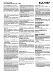
Figure 2: Changing the approach direction
Caution:
Caution:
Risk of damage to equipment as a result of incorrect
installation. Safety switches must not be used as a
mechanical end stop.
Fit an additional end stop for the movable part of
the safety guard.
ff
Protection against environmental effects
A lasting and correct safety function requires that the
actuating head must be protected against foreign
bodies such as swarf, sand, blasting shot, etc.,
which can become lodged in the recess. For this
purpose, the read head should be installed with the
actuating head facing down.
!
Observe the min. door radii (see Figure 3).
Ensure that the actuator contacts the slide in the
designated area (see figure below). Marks on
the slide specify the prescribed approach zone.
ff
Note the following points:
Actuator and safety switch must be easily accessible for inspection and replacement.
ffThe switching operation must only be triggered by
the specific actuator designated for this purpose.
ffActuator and safety switch must be fitted so that
ffthe actuator is positively mounted on the safety
guard, e.g. by using the safety screws included.
ffthey cannot be removed or tampered with using
simple means.
ffthe active faces of the actuator and the safety
switch are parallel to each other (see Figure 3).
ffthe actuator is fully inserted into the switch recess
when the safety guard is closed (see Figure 3).
ff
Deactivate guard locking and open the safety door
before using the lockout mechanism.
Before entering the danger area:
1. Open the door
Cover the actuating head, the actuator and the rating
plate during painting work!
Electrical connection
The read head CET is only allowed to be used in
combination with a suitable EUCHNER connection cable (see Table 1). The connection cable
contains two screened cores for the signal
from the read head. This screening must not be
interrupted on the route to the evaluation unit
or earthed at any other point (see Figure 8).
All the electrical connections must either be
isolated from the mains supply by a safety
transformer according to IEC EN 61558-2-6
with limited output voltage in the event of a
fault (PELV), or by other equivalent isolation
measures.
For use and operation as per the
requirements,
a power supply with the feature "for use in class 2
circuits" must be used. The same requirement applies to the safety outputs.
2. Press button, move lockout mechanism to
locking position (Figure 1 A and B) and secure
with lock (Figure C)
Pushbutton
ff
ff
Important:
Locking function not active
Remove the screws from the read head.
Set the required direction.
ffTighten the screws with a torque of 1.5 Nm.
ff
Safety switches must not be bypassed (bridging
of contacts), turned away, removed or otherwise
rendered ineffective.
ffOn this topic pay attention in particular to the
measures for reducing the possibility of bypassing
according to EN 1088:1995.A2:2008, Sec. 5.7.
Locking function active
Locking function active
and secured
Push button and
align lever
A
B
Fit lock
C
Figure 1: Function of lockout mechanism
EUCHNER GmbH + Co. KG Kohlhammerstraße 16 D-70771 Leinfelden-Echterdingen Tel. +49/711/75 97-0 Fax +49/711/75 33 16 www.euchner.de [email protected]
Subject to technical modifications, no responsibility is accepted for accuracy of this information. © EUCHNER GmbH + Co. KG 098069-16-11/12 (translation of the original operating instructions)
Operating Instructions Read Head CET-AX with Guard Locking and Guard Locking Monitoring