1
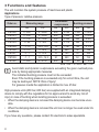
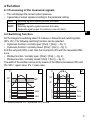
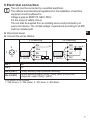
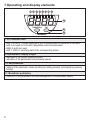
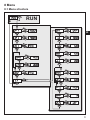
Operating instructions
Pressure sensor
UK
701844 / 00
10 / 2004
PN70XX
Contents
1 Preliminary note���������������������������������������������������������������������������������������������������3
1.1 Symbols used�������������������������������������������������������������������������������������������������3
2 Safety instructions������������������������������������������������������������������������������������������������3
3 Functions and features�����������������������������������������������������������������������������������������4
4 Function����������������������������������������������������������������������������������������������������������������5
4.1 Processing of the measured signals��������������������������������������������������������������5
4.2 Switching function������������������������������������������������������������������������������������������5
4.3 Diagnostic function�����������������������������������������������������������������������������������������6
5 Installation������������������������������������������������������������������������������������������������������������6
6 Electrical connection��������������������������������������������������������������������������������������������7
7 Operating and display elements ��������������������������������������������������������������������������8
8 Menu��������������������������������������������������������������������������������������������������������������������9
8.1 Menu structure�����������������������������������������������������������������������������������������������9
8.3 Explanation of the menu�������������������������������������������������������������������������������10
9 Parameter setting����������������������������������������������������������������������������������������������� 11
9.1 General parameter setting���������������������������������������������������������������������������� 11
9.2 Configuring the display (optional)�����������������������������������������������������������������13
9.3 Setting the output signals�����������������������������������������������������������������������������13
9.3.1 Setting of the output function���������������������������������������������������������������13
9.3.2 Setting of the switching limits��������������������������������������������������������������13
9.4 User settings (optional) �������������������������������������������������������������������������������14
9.4.1 Setting of a time delay for the switching signals����������������������������������14
9.4.2 Setting of the output logic for the switching outputs����������������������������14
9.4.3 Setting of the damping for the switching outputs���������������������������������14
9.5 Service functions������������������������������������������������������������������������������������������14
9.5.1 Reading the min./max. values for the system pressure����������������������14
10 Operation����������������������������������������������������������������������������������������������������������15
10.1 Reading of the set parameters�������������������������������������������������������������������15
10.2 Fault indication�������������������������������������������������������������������������������������������15
11 Scale drawing���������������������������������������������������������������������������������������������������16
2
12 Technical data���������������������������������������������������������������������������������������������������16
12.1 Setting ranges��������������������������������������������������������������������������������������������18
13 Factory setting��������������������������������������������������������������������������������������������������19
UK
1 Preliminary note
1.1 Symbols used
►
>
[…]
→
Instruction
Reaction, result
Designation of pushbuttons, buttons or indications
Cross-reference
Important note:
Non-compliance can result in malfunctions or interference.
2 Safety instructions
• Please read this document prior to set-up of the unit. Ensure that the product is
suitable for your application without any restrictions.
• If the operating instructions or the technical data are not adhered to, personal
injury and/or damage to property can occur.
• Check the compatibility of the product materials (→ chapter 12 Technical data)
with the media to be measured in all applications.
• For gaseous media the application is limited to max. 25 bar.
3
3 Functions and features
The unit monitors the system pressure of machines and plants.
Applications
Type of pressure: relative pressure
Order no.
PN7000
PN7001
PN7002
PN7003
PN7004
PN7006
PN7007
PN7009
PN7060
Measuring range
bar
0...400
0...250
0...100
0...25
-1...10
0...2.5
0...1
-1...1
0...600
PSI
0...5 800
0...3 625
0...1 450
0...363
-14.5...145
0...36.3
0...14.5
-14.5...14.5
0...8 700
Permissible
Bursting pressure
overpressure
bar
PSI
bar
PSI
600
8 700
1 000
14 500
400
5 800
850
12 300
300
4 350
650
9 400
150
2 175
350
5 075
75
1 087
150
2 175
20
290
50
725
10
145
30
450
20
290
50
725
800
11 600
1 200
17 400
MPa = bar ÷ 10 / kPa = bar × 100
Avoid static and dynamic overpressure exceeding the given overload pressure by taking appropriate measures.
The indicated bursting pressure must not be exceeded.
Even if the bursting pressure is exceeded only for a short time, the unit
may be destroyed. NOTE: Risk of injury!
For gaseous media the application is limited to max. 25 bar.
High-pressure units (400 bar, 600 bar) are supplied with an integrated damping
device to comply with the regulations for UL approval and to avoid any risk of
injury in case of bursting when bursting pressure is exceeded.
• When the damping device is removed the damping device can become unusable.
• When the damping device is removed the unit can no longer be used under UL
conditions.
If you have any questions, please contact ifm electronic’s sales specialists.
4
4 Function
4.1 Processing of the measured signals
• The unit displays the current system pressure.
• It generates 2 output signals according to the parameter setting.
OUT1
OUT2
• Switching signal for system pressure limit value.
2 options
• Switching signal for system pressure limit value.
• Diagnostic signal (output 2 is inactive in case of a fault).
UK
4.2 Switching function
OUTx changes its switching state if it is above or below the set switching limits
(SPx, rPx). The following switching functions can be selected:
• Hysteresis function / normally open: [OUx] = [Hno] (→ fig. 1).
• Hysteresis function / normally closed: [OUx] = [Hnc] (→ fig. 1).
First the set point (SPx) is set, then the reset point (rPx) with the requested difference.
• Window function / normally open: [OUx] = [Fno] (→ fig. 2).
• Window function / normally closed: [OUx] = [Fnc] (→ fig. 2).
The width of the window can be set by means of the difference between SPx and
rPx. SPx = upper value, rPx = lower value.
1
P
SP
HY
rP
P
SP
rP
t
1
0
1
0
2
FE
t
Hno
Hnc
1
0
1
0
Fno
Fnc
P = system pressure; HY = hysteresis; FE = window
5
4.3 Diagnostic function
Output 2 is used as diagnostic output based on the DESINA specification if
[OU2] = [dESI].
• If there is no fault, the output is switched and carries UB+ (if P-n = PnP) or UB(if P-n = nPn).
• In case of malfunctions in the following areas, the output is inactive:
-- Measuring cell defect,
-- short circuit in output 1,
-- exceeding / not reaching the limits of the measuring range,
-- EEPROM fault,
-- RAM fault,
-- processor fault.
5 Installation
Before mounting and removing the sensor, make sure that no pressure is
applied to the system.
►► Insert the unit in a G¼ process connection.
►► Tighten firmly.
6
6 Electrical connection
The unit must be connected by a qualified electrician.
The national and international regulations for the installation of electrical
equipment must be adhered to.
Voltage supply to EN50178, SELV, PELV.
For the scope of validity cULus:
The unit shall be supplied from an isolating source and protected by an
overcurrent device. The „limited voltage“ requirements according to UL508
must be complied with.
UK
►► Disconnect power.
►► Connect the unit as follows:
2 x p-switching
� ��
�
� ��
�
�
�
2 x n-switching
� ��
��
� ��
� ��
�������
�������
� ��
��
� ��
�
�������
�������
� ��
�
Pin 1
Pin 3
Pin 4 (OUT1)
Ub+
Ub• binary switching output pressure monitoring
• binary switching output if [OU2] = [Hno], [Hnc], [Fno] or [Fnc]
Pin 2 (OUT2)
• diagnostic output if [OU2] = [dESI]
Core colours of ifm sockets:
1 = BN (brown), 2 = WH (white), 3 = BU (blue), 4 = BK (black)
7
7 Operating and display elements
� � � � � � � �
�
����������
���
��
��
1 to 8: Indicator LEDs
-- LED 1 to LED 4 = system pressure in unit of measurement as indicated on the label.
-- LED 4 not used for units with 3 adjustable units of measurement.
-- LEDs 5 and 6 not used.
-- LED 7, LED 8 = switching state of the corresponding output.
9: Alphanumeric display, 4 digits
-- Indication of the current system pressure.
-- Indication of the parameters and parameter values.
10: Set pushbutton
-- Setting of the parameter values (scrolling by holding pressed, incremental by pressing
briefly).
11: Mode/Enter pushbutton
-- Selection of the parameters and acknowledgement of the parameter values.
8
8 Menu
8.1 Menu structure
���
�
�
�
�
�
�
�
�
�
�
�
�
�
�
�
�
�
�
�
�
�
�
�
�
�
�
�
�
�
�
�
�
�
UK
�
�
�
�
�
�
�
�
�
�
�
�
�
�
�
�
�
�
9
8.3 Explanation of the menu
SP1/rP1
Upper / lower limit value for system pressure at which OUT1 switches.
SP2/rP2
Upper / lower limit value for system pressure at which OUT2 switches.
OU1
Output function for OUT1:
• Switching signal for the pressure limit values: hysteresis function [H ..] or
window function [F ..], either normally open [. no] or normally closed [. nc].
OU2
Output function for OUT2:
• Switching signal for the pressure limit values: hysteresis function [H ..] or
window function [F ..], either normally open [. no] or normally closed [. nc].
• Diagnostic signal [OU2] = dESI.
EF
Extended functions / opening of menu level 2.
Uni Standard unit of measurement for system pressure.
HI Maximum value memory for system pressure.
LO Minimum value memory for system pressure (only PN7004 and PN7009).
dS1/dS2 Switch-on delay for OUT1 / OUT2.
dr1/dr2 Switch-off delay for OUT1 / OUT2.
P-n Output logic: pnp / npn.
dAP Damping for the switching outputs.
diS Update rate and orientation of the display.
10
9 Parameter setting
During parameter setting the unit remains in the operating mode. It continues its
monitoring function with the existing parameters until the parameter setting has
been completed.
9.1 General parameter setting
3 steps must be taken for each parameter setting:
1
Parameter selection
►► Press [Mode/Enter] until the requested parameter is displayed.
UK
���������� ���
2
Setting of the parameter value
►► Press [Set] and keep it pressed.
>> Current setting value of the param���������� ���
eter flashes for 5 s.
>> After 5 s: setting value is changed:
incrementally by pressing the button
once or continuously by keeping the
button pressed.
Numerical values are incremented continuously. To reduce the value: let the display
move to the maximum setting value. Then the cycle starts again at the minimum
setting value.
3 Acknowledgement of the parameter
value
►► Press [Mode/Enter] briefly.
���������� ���
>> The parameter is displayed again.
The new setting value is stored.
Setting of other parameters:
►► Start again with step 1.
Finishing the parameter setting:
►► Press [Mode/Enter] several times until the current measured value is displayed or wait
for 15 s.
>> The unit returns to the operating mode.
11
• Change from menu level 1 to menu level 2:
►► Press [Mode/Enter] until [EF] is
displayed.
If the submenu is protected with an access code,"Cod1" flashes in the display.
►► Press [Set] and keep it pressed until
the valid code no. is displayed.
►► Press [Mode/Enter] briefly.
On delivery by ifm electronic: no access
restriction.
►► Press [Set] briefly.
>> The first parameter of the sub-menu
is displayed (here: [Uni]).
���������� ���
���������� ���
• Locking / unlocking
The unit can be locked electronically to prevent unintentional settings.
►► Make sure that the unit is in the
normal operating mode.
►► Press [Mode/Enter] + [Set] for 10 s.
>> [Loc] is displayed.
���������� ���
����
During operation: [Loc] is briefly displayed if you try to change parameter values.
For unlocking:
►► Press [Mode/Enter ] + [Set] for 10 s.
���������� ���
>> [uLoc] is displayed.
����
On delivery: unlocked.
• Timeout:
If no button is pressed for 15 s during parameter setting, the unit returns to the operating mode with unchanged values.
12
9.2 Configuring the display (optional)
►► Select [Uni] and set the unit of of measurement:
-- [bar], [mbar], [MPa], [kPa], [PSI],
for PN7007 and PN7009 in addition [inHg].
►► Select [diS] and set update rate and orientation of the display:
-- [d1]: Update of the measured value every 50 ms.
-- [d2]: Update of the measured value every 200 ms.
-- [d3]: Update of the measured value every 600 ms.
-- [rd1], [rd2], [rd3]: Display like d1, d2, d3; rotated by 180°.
-- [OFF]: The display is deactivated in the operating mode.
UK
9.3 Setting the output signals
9.3.1 Setting of the output function
►► Select [OU1] and set the function:
-- [Hno] = hysteresis function / normally open
-- [Hnc] = hysteresis function / normally closed,
-- [Fno] = window function / normally open,
-- [Fnc] = window function / normally closed
►► Select [OU2] and set the function:
-- [Hno] = hysteresis function / normally open,
-- [Hnc] = hysteresis function / normally closed,
-- [Fno] = window function / normally open,
-- [Fnc] = window function / normally closed,
-- [dESI] = output 2 is used as a diagnostic output.
9.3.2 Setting of the switching limits
►► Select [SP1] / [SP2] and set the value at which the output switches.
►► Select [rP1] / [rP2] and set the value at which the output switches off.
rPx is always smaller than SPx. The unit only accepts values which are
lower than the value for SPx.
13
9.4 User settings (optional)
9.4.1 Setting of a time delay for the switching signals
[dS1] / [dS2] = switch-on delay for OUT1 / OUT2.
[dr1] / [dr2] = switch-off delay for OUT1 / OUT2.
►► Select [dS1], [dS2], [dr1] or [dr2] and set a value between 0.1 and 50 s
(at 0.0 the delay time is not active).
9.4.2 Setting of the output logic for the switching outputs
►► Select [P-n] and set [PnP] or [nPn].
9.4.3 Setting of the damping for the switching outputs
►► Select [dAP] and set a value.
dAP value = response time between pressure change and change of the
switching status in milliseconds.
The following fix values can be set; they define the switching frequency (f)
of the output:
dAP
3
6
10
17
30
60
125
250
500
f [Hz]
170
80
50
30
16
8
4
2
1
9.5 Service functions
9.5.1 Reading the min./max. values for the system pressure
►► Select [HI] or [LO], press [Set] briefly.
[HI] = maximum value, [LO] = minimum value.
Delete memory:
►► Select [HI] or [LO].
►► Press [Set] until [----] is displayed.
►► Press [Mode/Enter] briefly.
[LO] is available only for PN7004 and PN7009.
14
10 Operation
After power on, the unit is in the Run mode (= normal operating mode). It carries
out its measurement and evaluation functions and provides output signals according to the set parameters.
Operating indications → chapter 7 Operating and display elements.
10.1 Reading of the set parameters
►► Press [Mode/Enter] until the requested parameter is displayed.
►► Press [Set] briefly.
>> The unit displays the corresponding parameter value for about 15 s. After
another 15 s the unit returns to the Run mode.
UK
10.2 Fault indication
[OL]
Overload pressure (measuring range exceeded)
[UL]
Underload pressure (below measuring range)
[SC1] Short circuit in OUT1*
[SC2] Short circuit in OUT2*
[SC]
Short circuit in both outputs*
[Err]
Flashing: internal fault
*The output concerned is switched off as long as the short circuit exists.
The messages SC1, SC2, SC, and Err are shown even if the display is switched off.
15
11 Scale drawing
�
�
��
��� ��
��
���
����
������
����
������
����
������
�
����
��
��
� ���
Dimensions are in millimeters
1)
= dimensions for PN7000 and PN7060
1: display
2: LED’s
3: programming button
12 Technical data
Operating voltage [V]...........................................................................................18...36 DC1)
Current consumption [mA].............................................................................................. < 50
Current rating per switching output [mA]......................................................................... 250
Reverse polarity protection, overload protection.................................................. up to 40 V
Short-circuit protection; Integrated watchdog
Voltage drop [V] ............................................................................................................... < 2
Power-on delay time [s] ................................................................................................... 0.3
Switching frequency [Hz] .........................................................................................max.170
16
Accuracy / deviations (in % of the span)
- Set point accuracy .................................................................................................. < ± 0.5
- Deviation of the characteristics .......................................... < ± 0.25 (BFSL) / < ± 0.5 (LS)
- Hysteresis..................................................................................... < 0.25 (0.5 for PN7060)
- Repeatability (in case of temperature fluctuations < 10 K).......................................< ± 0.1
- Long-term stability (in % of the span per 6 months) ............................................. < ± 0.05
- Temperature coefficients (TEMPCO) in the compensated
temperature range 0 ... 80 °C (in % of the span per 10 K)
- Greatest TEMPCO of the zero point / of the span ................................... < ± 0.2 / < ± 0.2
Materials (wetted parts) ............................stainless steel (303S22); ceramics; FPM (Viton)
Housing material .........stainless steel (304S15); stainless steel (316S12); PBTP (Pocan); UK
PEI; FPM (Viton); EPDM/X (Santoprene)2)
Protection .............................................................................................................. IP 67 III3)
Protection .............................................................................................................. IP 65 III4)
Insulation resistance [MΩ] ........................................................................ > 100 (500 V DC)
Shock resistance [g] .............................................................. 50 (DIN / IEC 68-2-27, 11ms)
Vibration resistance [g] ............................................... 20 (DIN / IEC 68-2-6, 10 - 2000 Hz)
Switching cycles min. ....................................................100 million (50 million for PN7060)
Operating temperature [°C] ............................ -20...80 (UB < 32 V) / -20...60 (UB > 32 V)
Medium temperature [°C] ..................................................................................... -25 ... +80
Storage temperature[°C]................................................................................... -40 ... +100
EMC EN 61000-4-2 ESD: .......................................................................................4 / 8 KV
EN 61000-4-3 HF radiated: ............................................................................ 10 V/m
EN 61000-4-4 Burst: ...........................................................................................2 KV
EN 61000-4-5 Surge: ..................................................................................0.5 / 1 KV
EN 61000-4-6 HF conducted: ............................................................................ 10 V
to EN50178, SELV, PELV
2)
in addition PTFE for PN7003...PN7009
3)
for PN7000...PN7002, PN7060
4)
for PN7003...PN7009
BFSL = Best Fit Straight Line / LS = Limit Value Setting
1)
17
12.1 Setting ranges
PN7009
PN7007
PN7006
PN7004
PN7003
PN7002
PN7001 PN7000
SP1 / SP2
ΔP
min
max
min
max
bar
4
400
2
398
2
PSI
60
5790
30
5760
30
MPa
0.4
40.0
0.2
39.8
0.2
bar
2
250
1
249
1
PSI
40
3620
20
3600
20
MPa
0.2
25.0
0.1
24.9
0.1
bar
1.0
100.0
0.5
99.5
0.5
PSI
20
1450
10
1440
10
MPa
0.10
10.00
0.05
9.95
0.05
bar
0.2
25.0
0.1
24.9
0.1
PSI
4
362
2
360
2
MPa
0.02
2.50
0.01
2.49
0.01
bar
-0.90
10.00
-0.95
9.95
0.05
PSI
-12
145
-13
144
1
MPa
-0.090
1.000
-0.095
0.995
0.005
bar
0.02
2.50
0.01
2.49
0.01
PSI
0.4
36.2
0.2
36.0
0.2
kPa
2
250
1
249
1
mbar
10
1000
5
995
5
PSI
0.2
14.5
0.1
14.4
0.1
kPa
1.0
100.0
0.5
99.5
0.5
inHg
0.3
29.5
0.2
29.4
0.1
mbar
-970
1000
-980
990
10
PSI
-14.0
14.4
-14.2
14.2
0.2
kPa
-97.0
100.0
-98.0
99.0
1.0
inHg
-28.8
29.4
-29.1
29.1
0.3
ΔP = increments
18
rP1 / rP2
PN7060
SP1 / SP2
rP1 / rP2
ΔP
min
max
min
max
bar
6
600
3
597
3
PSI
100
8700
50
8650
50
MPa
0.6
60.0
0.3
59.7
0.3
ΔP = increments
13 Factory setting
Factory setting
SP1
25% VMR*
rP1
23% VMR*
OU1
Hno
OU2
Hno
SP2
75% VMR*
rP2
73% VMR*
dS1
0.0
dr1
0.0
dS2
0.0
dr2
0.0
P-n
PnP
dAP
60
diS
d2
Uni
bAr / mbAr
UK
User setting
* = the indicated percentage of the final value of the measuring range (VMR) of the
corresponding sensor in bar / mbar is set.
Further information at www.ifm.com
19