1
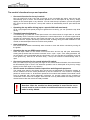
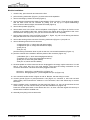
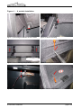
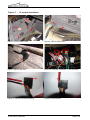
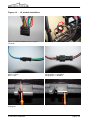
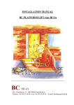
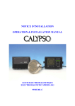
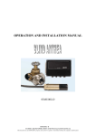
Dipl.-Inf. Andreas Reinhold · Blumenstr. 36 · D-97332 Volkach · Fax: +49-9381-710656 · Mobile: +49-170-8548257
Installation and Operating Instructions
VW EOS Comfort-Module
Before installation:
Please read these instructions carefully and take your time with the installation. Performing
the installation improperly can cause damage to the module or to electronic components in
your vehicle. Claims cannot be asserted for consequences which arise out of disregard for
these installation instructions. If you are not confident in doing the installation yourself, please
obtain the services of a vehicle specialist.
!
Attention: Installation of this module may be grounds to invalidate your
vehicle's homologation (general type certification) and/or its manufacturer's
warranty. Do not operate the convertible top without the presence of another
person – there is no entanglement protection.
The installation and operation of the module is at your own risk.
Functional description:
The module only uses functions which were originally built into the vehicle. All data relevant to
convertible top control (e.g. limit switches, window position, speed) will be continuously
monitored. All OEM safety functions (under / over voltage cut-off, thermal protection, etc.)
remain intact.
© www.cabrio-module.de
page 1 of 6
Dipl.-Inf. Andreas Reinhold · Blumenstr. 36 · D-97332 Volkach · Fax: +49-9381-710656 · Mobile: +49-170-8548257
The module's functional scope and operation:
•
One touch function for the top's switch:
Now you need only to tap (>2s) with your finger on the convertible top switch, then the top will
automatically open or close. This automatic operation can be interrupted at any time by simply
tapping on the switch again in any direction. You can start the top's operation, pull out the ignition
key, get out of the car and lock it – the top will continue to automatically close or open without the
ignition.
•
Operating the top while driving (up to a speed of 60 km/h maximum):
Up to a pre-programmed speed (though not greater than 60 km/h), you can operate the top while
driving.
•
Threshold speed adjustment:
If, while driving, you press the central open button in the drivers door for longer than 4s, this will
automatically set the vehicle's current speed as the new threshold limit. An acoustic signal will be
sounded as confirmation that the new speed has been set. The maximum permissible threshold
speed is 60 km/h. Anytime the battery is disconnected, including during the initial installation of the
module, a threshold speed of 50 km/h will be set by default.
•
Auto lock/unlock:
The vehicle will be locked automatically when it starts to move and will be unlocked by turning off
the ignition.
•
Operating the top per OEM remote control:
Press the Open switch on the remote control three times and the top will open automatically.
Closing the top works with the remote command "close – open – open". As a safety precaution, the
top movement can be terminated with the close button. You can start the top's operation, then pull
in the ignition key, start the car and drive away – the top will continue to automatically close or
open.
•
One touch operation for the central window lift switch:
Now you need only to tap (>2s) with your finger on the central window lift switch, then the windows
will automatically open or close. This automatic operation can be interrupted at any time by simply
tapping on the switch again in any direction.
•
Service mode for technical vehicle inspections and diagnostic purposes:
The central open switch in the drivers door can be held >4s depressed to activate the module, to
set the module into service mode (deactivate it) use the central lock. The module is completely
passive in service mode, i.e. all functions operate as if no module was installed. The module cannot
even be detected with vehicle diagnostic equipment. An acoustic signal will be sounded as
confirmation when mode has changed. Service mode is set by default after the battery has been
disconnected or after the module is initially installed.
!
Attention: After the module has been installed it must first be set to
normal mode in order to obtain its additional features because service
mode is set by default.
© www.cabrio-module.de
page 2 of 6
Dipl.-Inf. Andreas Reinhold · Blumenstr. 36 · D-97332 Volkach · Fax: +49-9381-710656 · Mobile: +49-170-8548257
Module installation:
1. close the top, open the trunk and remove the floor
2. pull out locking mechanism (Figure 1) to remove the trunk separation
3. remove mounting by loosen the screw (Figure 2)
4. remove warning triangle and 2 plastic rivets behind it (Figure 3 and 4). Then lift the trunk sealing
that the back cover can be removed by pulling it to the top (it is clipsed additionally).
Note: the wire to the trunk light must be disconnected (Figure 5)
5. remove bump rubber (Figure 6)
6. remove side cover in the trunk: remove all plastic rivets (Figure 7 and Figure 8). Pull the cover
carefully to the middle of the trunk, note the wire to the switch which is connected to the cover.
Disconnect the wire (Figure 9), now you can remove the side cover completely.
7. pull out right connector of the roof ECU (connector 1, Figure 10): pull out red locking mechanism
and push the black one to remove the connector
8. remove the housing of the connector: lift locking mechanism (Figure 11) and pull out
9. remove following wires from the connector:
- orange/green (Pin 1, orange wire with green stripe)
- orange/brown (Pin 2, orange wire with brown stripe)
- green (Pin 9)
- blue (Pin 10)
push the locking mechanism down to pull out the wire, use a small screwdriver (Figure 12)
10. push the contacts of the module in the free places of the connector (Figure 13):
- yellow/black (Pin 1, which was orange/green before)
- grey/black (Pin 2, which was orange/brown before)
- green (Pin 9, which was green before)
- blue (Pin 10, which was blue before)
11. the wires pulled out of the connector have to be plugged in the empty 2-pole connectors. You will
hear a “click” when they are in the right position. Then push the locking mechanism on the
connector downwards. The wires have to be plugged in like this:
connector 1: green (Pin 1) und blue (Pin 2) (Figure 15)
connector 2: orange/green (Pin 1) and orange/brown (Pin 2) (Figure 16)
12. now connect them like shown in figure 15 and 16. Be sure, that the wiring is correct.
13. connect ground (Figure 14) and permanent +12V (Figure 10, connector 2, wire color red with
yellow stripe). We recommend to solder the +12V connection, this is the safest way to connect
two wires.
14. test the module: push a screwdriver into the trunk lock (Figure 17), now you should hear the lock
motor running. You can unlock it when you stick the srewdriver in it (Figure 18)
Press the central open button in the drivers door for > 5s, then a acoustic signal will come up to
show that the module is enabled now.
15. assembly everything in the reverse order
© www.cabrio-module.de
page 3 of 6
Dipl.-Inf. Andreas Reinhold · Blumenstr. 36 · D-97332 Volkach · Fax: +49-9381-710656 · Mobile: +49-170-8548257
Figures 1 … 6, module installation:
Figure 1: pull locking mechanism as arrow shows
Figure 2: remove mounting
Figure 3: remove warning triangle and plastic rivets
Figure 4: remove plastic rivets
Figure 5: remove connector
Figure 6: remove bump rubber
© www.cabrio-module.de
page 4 of 6
Dipl.-Inf. Andreas Reinhold · Blumenstr. 36 · D-97332 Volkach · Fax: +49-9381-710656 · Mobile: +49-170-8548257
Figures 7 … 12, module installation:
Figure 7: remove plastic rivets
Figure 8: remove plastic rivets
2
1
Figure 9: pull out connector
Figure 10: roof ECU: connectors, +12V-connection
Figure 11: remove connector's housing
Figure 12: remove wires
© www.cabrio-module.de
page 5 of 6
Dipl.-Inf. Andreas Reinhold · Blumenstr. 36 · D-97332 Volkach · Fax: +49-9381-710656 · Mobile: +49-170-8548257
Figures 13 … 18, module installation:
Figure 13: wires of comfort-module plugged in
connector
Figure 14: ground connection
Figure 15: pinout connector 1:
green <> green
blue <> blue
Figure 16: pinout connector 2:
orange/brown <> grey/black
orange/green <> red/black
Figure 17: test the module, push screwdriver in
locking unit
Figure 18: release locking unit
© www.cabrio-module.de
page 6 of 6