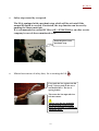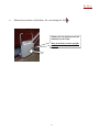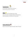
1
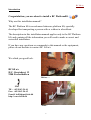
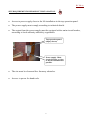
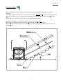
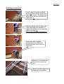
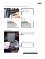
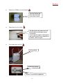
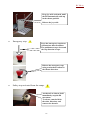
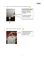
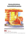
INSTALLATION MANUAL
BC PLATFORM LIFT type BCSA
BC lift a/s
H.C. Oerstedsvej 13 - DK-9900 Frederikshavn
Telefon +45 98 43 54 44 - Fax +45 98 43 54 45 – E-mail: [email protected]
BC lift a/s
Contents.
Text
Section
Introduction……..…………………….……………….
2
Tecnical details………………………………..………..
3
Site requirements before lift installation………….….
4
Arriving on installation site …………………………..
5
Check all lift parts before installation start…..……...
6
Installation………………………………………………
7
Test……………………………………………………..
25
Cleaning lift and site. Initial lubrication……………..
32
User instruction………………………………………..
33
Notes…………………………………….………………
34
1
BC lift a/s
Introduction
Congratulation, you are about to install a BC Platformlift.
Why use this installation manual?
The BC Platform lift is an advanced staircase platform lift, specially
developed for transporting a person with or without a wheelchair.
The description in this installation manual applies only to the BC Platform
lift, and contains all the information you will need to make a correct and
succesfull installation.
If you have any questions or commends to this manual or the equipment,
please do not hesitate to contact BC Lift a/s
We whish you good luck.
BC lift a/s
H.C. Oerstedsvej 13
9900 Frederikshavn
Before….
Tlf.: +45 98 43 54 44
Fax.: +45 98 43 54 45
E-mail: [email protected]
http:\\www.bclift.dk
After.
2
BC lift a/s
TECHNICAL DETAILS.
General
Power supply voltage
3x380 VAC/1x220VAC Rate of movement
12 cm/s
Frequency
50 Hz
Max. load on platform
225 kg
Current consumption
2.4 Amp
Relative humidity
10%-90%
Power consumption
0.55 kW
IP value
66
Fuses
8 Amp
3
BC lift a/s
SITE REQUIREMENTS BEFORE LIFT INSTALLATION.
•
Access to power supply close to the lift installation in the top operation panel.
•
The power supply must comply according to technical details.
•
The output from the power supply must be equipped with a main circuit breaker,
according to local authority and safety regulations.
Top operation panel
(empty shown)
Power supply. Main
circuit breaker as close
to the lift installation as
possible.
•
The site must be clean and free from any obstacles.
•
Access to power for hand tools.
4
BC lift a/s
ARRIVING ON INSTALLATION SITE.
•
Introduce yourself to the client.
•
Hand over the user manual to the client. The client can
then become familiar with the content of the manual, before
user instruction will take place.
•
Check that the staircase is the same as that shown on the
installation drawing.
•
Check that site requirements before installation has been fulfilled.
•
Bring in all the lift parts.
•
Bring in all tools needed.
5
BC lift a/s
CHECK ALL LIFT ITEMS BEFORE INSTALLATION START.
In order to reduce installation time and avoid unneccesary waste time,
following lift items must be present before installation start.
•
•
•
•
•
•
•
•
•
•
•
•
•
•
Main rail.
Main rail end covers.
Supporting rail.
Lift body.
Lift body shell.
Lift platform.
Top operating panel.
Bottom operating panel.
Platform kit.
Bolts with expansion plugs,
for either wall-or foot mounted rails.
Electrical cables
Safety bars
Support wheels
Emergency handle.
6
BC lift a/s
INSTALLATION.
Before installation can be initiated, the following basic measurements and conditions must be
observed.
According to enclosed drawing, it is important to locate the straight line X, starting from the top of the
staircase, called the top nose, down on top of the highest step and finally ending in point X on the
floor.
We already have the slope of the staircase, determined at order time.
Using enclosed table, we can now find the two measurements a and b.
Measure a is the angular distance from line X to the upper side of the main rail.
Measure b is the angular distance between the lower side of the main rail and the upper side of the
supporting rail.
7
BC lift a/s
Installing the main rail.
Use the supporting rail to establish
the line X. Make sure the rail is hold
tight on the top nose. The highest step
further down will then determine the
slope of line X.
When measuring from the upper side
of the supporting rail, remember to
suptract the thicknes of the supporting
rail from measure a.
Always take an angular measurement.
Always take min. 3 angular
measurements down the line to
position the main rail as accurate
as possible.
Remove cover on main rail,
to get access to the tooth
bar.
Mount ajustable supports for
lining up. (not standard).
8
BC lift a/s
Supporting rail.
Main rail with two supports.
Main rail is adjusted on the
two supports so the marking
on the wall, fits along with
the upper side of the main
rail.
The end of the main rail
should be vertical above the
top nose of the staircase.
Check for free space.
Make sure that nothing
exeeds the main rail
9
BC lift a/s
Drill all the holes.
Diameter: 12 mm.
Depth: min. 100 mm.
Insert: Plugs U12
and tight with screw:
M10 x 90.
In this situation,
a special designed
rail support is needed
for the lower end of
the main rail.
Support used: Type V
The main rail is now installed.
10
BC lift a/s
Installing the supporting rail.
The angular distance b from
under side of main rail to upper
side of supporting rail, is
marked.
Drill all the holes.
Diameter: 8 mm.
Depth: min. 100 mm.
Insert: Plugs U8
and tight with screw:
M6 x 100.
The supporting rail should
reach the ground/floor.
Rail installation completed.
Installation of Main - and Supporting rails are completed.
11
BC lift a/s
Installing operating panels and cable ducting.
Installation of operating
panel, downstairs.
Installation of operating
panel, upstairs.
Cable ducting.
Installation of operating panels and cable ducting are completed.
12
BC lift a/s
Installing lift body.
Remove the upper
end-stop.
Back side of the lift body.
Remember to loosen the cable,
before inserting the wheels in
the track of the main rail.
Insert from upper end.
Lift is inserted from the upper
end.
Lift is now hanging freely.
13
BC lift a/s
Installing support wheels on the lift body.
Use a spirit level, for the
horizontal alignment .
Tight this bolt in each side.
Liftbody is now hanging
vertical, and this hole must
point directly to middle of the
support rail.
Drill a hole that points direct to
the midle of the supporting rail.
See next picture.
14
BC lift a/s
The hole must be within the
penetration on the backplate,
and modified into a square of
approx. the shown size.
Support wheels installed.
Do not tight the bolts
yet.
Use a spirit level, for the
vertical alignment.
Use nuts and counter nuts to
set the vertical alignmentn
and tight all well.
Installation of lift body is now completed.
15
BC lift a/s
Installation of electrical cables.
Cable from lift body is
inserted in the free end of the
flexible cable ducting .
The free end of the flexible
ducting, is pulled up to the
back side of the lift body.
The free end of the flexible
ducting, is locked/clipsed on
the back side of the lift
body.
Cable from the lift, comming
from the flexible ducting, to
the upper control panel.
Cable to the lower control
panel, comming from the
upper control panel, is
inserted in track in the
aluminium rail, i.e. main
rail.
16
BC lift a/s
Lower Control panel.
The terminals are numbered
according to the wires in the
cable, i.e. 1-2-3-5-6-7-8-9-1011.
NOTE!! Wire number 4 and
Earth are not used in the
terminal.
Upper control panel.
Terminals to LIFT, are
numbered according to the
wires in the cable, i.e. 1-2-3-45-6-7-8-9-10-11 and Earth.
Upper control panel.
Terminals to SUPPLY.
Connect 3 phases + E+N
according to terminal marks.
Upper control panel.
Terminals to the LOWER
control panel, are numbered
according to the wires in the
cable, i.e. 1-2-3-5-6-7-8-9-1011.
NOTE!! Wire number 4 and
Earth are not used in the
terminal.
Installation of electrical cables are now completed.
17
BC lift a/s
Installation of lift platform.
Platform kit.
Bolt temporary inserted.
Platform on lift body.
Bolt temporary inserted.
Assembly of arm for platform
turning damper.
Arm for platform turning
damper.
Arm mounted between the lift
console and lift body flanges.
In the other side:
Arm for platform actuator
mounted between the lift
console and lift body flanges.
18
BC lift a/s
Arm in position.
Nylon shim inserted.
Bowden cable fixpoint.
Installation of Bowden cables to ramps.
Remove the rubber
gaskets from bowden
cable ends, and push
cable totally into the
fixpoint and lock it
with the centre screw.
Centre of screw must
hit this groove.
Bowden cable fixpoint
with center screw.
Rubber gaskets remounted.
Loosen the bowden
cable upper fixpoint
with an Allen key.
Turn the cable around,
so it lays flat to the lift
body. Tigh again.
See next picture.
19
BC lift a/s
Bowden cables are now
laying flat to the lift body,
so outwards pressure on
the body shell is avoided.
Electrical connection of platform to panel in lift body.
Remove the two short links
between terminal 33-34 and
35-36.
Cable from platform is
connected as follows:
Blue wire to terminal 33.
Brown wire to terminal 34.
Black wire to terminal 35.
Black wire to terminal 36.
20
BC lift a/s
Installation of safety bars.
Safety bar.
Insert the safety bar on the
spline shaft and use the bolt
to fasten the safety bar light
before alignment.
Use a spirit leveller to ajust
the safety bar into horizontal
position.
Tight the bolt as shown.
Ajustment of limit stop.
Ajust the lower limit stop
so the platform will hang
just above the
ground/surface when the
lift is stopped.
21
BC lift a/s
The lower ramp must have
good contact to the ground/
surface when the lift has
stopped in lower position and
the ramp is tilted down.
Ajust the upper limit stop so the platform
will hang just above the nose of the top
step when the lift is stopped.
Make sure the upper ramp
has good contact to the top
surface of the stair, when the
ramp is tilted down.
22
BC lift a/s
Ajustment of platform angle.
Use an Allen key and a
spirit leveller to ajust the
platform angle.
Platform angle on first time
ajustment: app. 2° above
horizontal.
Installing device for platform actuator.
Tools and bolt/nut.
Bolt/nut.
Do not tight too much,
since the parts must be
able to turn.
Arm already installed.
Actuators moving part.
23
BC lift a/s
Max. load adjustment on platform motor and safety bars.
Potentiometer.
Upper safety bar.
Adjustment of allowed
force of blockage, before
safety system breaks off
and stop the movement.
Potentiometer.
Lower safety bar.
Adjustment of allowed
force of blockage, before
safety system breaks off
and stop the movement.
Potentiometer.
Platform motor.
Adjustment of allowed
force of blockage, before
safety system breaks off
and stop the movement.
Mounting covers.
Lift body cover is mounted.
Covers on both ends on the
main rail is mounted, using
2 pcs. of selfcutting screws
per cover.
INSTALLATION COMPLETE.
24
TEST.
Test and check the following points:
•
Functions on Operating panels.
Activate this button
and the lift shall move
upstairs.
If the platform is in
horizontal position,
and safety bars are in
vertical position, the
bars will first move
into approx.
horizontal position,
before lift starts to
move.
Activate this button
and the lift platform
and the safety bars
shall move into
vertical position.
Green indicator lamp.
Activate this button
and the lift platform
shall move into
horizontal position,
and the safety bars
shall move into
vertical position.
Key switch.
Insert key and turn, until light in
the green lamp. The green lamp will
also lighten in the other panel.
Both panels has correspondence,
which means that the system can be
activated in either panel.
Lift is now in Stand-by.
Remove the key.
Activate this button
and the lift shall move
downstairs.
If the platform is in
horizontal position,
and safety bars are in
vertical position, the
bars will first move
into approx.
horizontal position,
before lift starts to
move.
Only the key can be used to close
the system again.
25
BC lift a/s
•
Function of Main circuit breaker.
Turn the button and
check that functions
on the lift are dead.
•
Functions on Joy stick.
The directional movement on both
the lift and joy-stick must always
correspond.
If not, open the upper control panel
and switch 2 phases on terminals for
SUPPLY, and test again.
•
User functions on lift.
Lift is parked.
Activate key switch.
Activate to switch down platform.
26
BC lift a/s
Safety bars open.
Platform down.
Ramps down.
Activate joy-stick i up-stairs
direction.
safety bars closes.
Ramps are lifted.
Keep joy-stick activated.
Keep joy-stick activated,
until the lift automatically
ends up in the shown
position.
Release the joy-stick.
Activate joy-stick in
down stairs direction.
27
BC lift a/s
Keep joy-stick activated, until
the lift automatically ends up
in the shown position.
Release the joy-stick.
•
Emergency stop.
Press the emergency stop down.
All functions must terminate.
The pushbutton stays down and
the stop function is kept.
Release the emergency stop,
using a twisted movement in
the shown direction.
•
Safety stop activated from the ramps.
An obstacle as shown, shall
immediately stop the lift
movement.
To release, run the lift in
the other direction, and
remove the obstacle.
28
BC lift a/s
•
Safety stop activated from the bottom part of platform.
An obstacle underneath the
platform, lift the movable
under part, and shall
immediately stop the lift
movement.
To release, run the lift in
the other direction, and
remove the obstacle.
•
Safety stop on safety bar movements.
If the automatic movement
on the safety arms are
blocked, the movement
immediately stops.
29
BC lift a/s
•
Safety stop caused by overspeed.
The lift is equipped with a mechanic stop, which will be activated if the
normal lift speed is exeeded. If activated, the stop function can be reset by
pushing the shown metal pin.
It is recommended to contact BC lift a/s tlf. +45 98435444 or an other service
company in case of above mentioned event.
Push the pin to reset
mechanic stop.
•
Manual movements of safety bars, for evacuating the lift.
First push the bar against the lift
body. Always push in the curve
and hold it there. The bar is
spring loaded.
Then turn the bar upwards in a
soft movement.
Always reset the bar manually
into horizontal position again,
before it is possible to continue in
automatic mode.
30
BC lift a/s
•
Manual movements of platform, for evacuating the lift.
Simply take the platform and lift
manually by the hand.
Must be hold by hand in upright
position.
31
BC lift a/s
Cleaning lift and site.
Clean the lift using a moisted cloth with a soft detergent.
Clean the site using a sweeper or a vacuum cleaner
NOTE!!!!!
NEVER CLEAN, USING A HIGH PRESSURE CLEANER.
NEVER CLEAN USING A HOSE WITH NORMAL WATER PRESSURE.
NEVER WASH DIRECT ON ELECTRICAL INSTALLATIONS.
INITIAL LUBRICATION.
Lubricate the tooth bar, using a low viscosity syntetic oil on spray.
32
BC lift a/s
USER INSTRUCTION.
NOTE !!! THIS PART OF THE WORK MUST ALWAYS BE DONE.
•
Explain the operation of the installation with the aid of the user`s manual.
•
Check that everything is fully understood, by letting the user demonstrate the
functions for you.
33
BC lift a/s
NOTES.
34