1
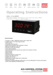
User manual M2 User manual M2 Strain gauge amplifier with a calibration for 350 Ω melt pressure sensors Strain gauge amplifier with a calibration for 350 Ω melt pressure sensors Operating Instructions DAL-111x900S Strain gauge amplifier with a calibration for 350 Ω melt pressure sensors Technical features: Technical features: • red display of -19999…99999 Digits (optional: green, orange or blue display) •• minimal installation depth: 70 mm without plug-in screw terminal red display of -19999…99999 Digits (optional: green, orange or blue display) •• min/max-memory minimal installation depth: 70 mm without plug-in screw terminal •• 30 additional adjustable supporting points min/max-memory •• display flashing at threshold value exceedance / threshold value undercut 30 additional adjustable supporting points •• zero-key for triggering of hold, Tara or sensor alignment display flashing at threshold value exceedance / threshold value undercut •• digital input triggering of hold, Tara or sensor alignment zero-key forfor triggering of hold, Tara or sensor alignment •• permanent min/max-value recording digital input for triggering of hold, Tara or sensor alignment •• sensor alignment with integrated switching output permanent min/max-value recording •• mathematic functions reciprocal value, square sensor alignment withlike integrated switching output root, squaring or rounding •• sliding average determination mathematic functions like reciprocal value, square root, squaring or rounding •• brightness control sliding average determination •• programming interlock via access code brightness control •• protection class IP65 atvia theaccess front side programming interlock code •• plug-in screw terminal protection class IP65 at the front side •• optional: 2 relay outputs plug-in screw terminal •• accessories: PC-based optional: 2 relay outputsconfiguration-kit PM-TOOL with CD & USB-adapter for devices without keypad andconfiguration-kit for a simple adjustment of with standard • accessories: PC-based PM-TOOL CD &devices USB-adapter for devices without keypad and for a simple adjustment of standard devices M2_1MGB.pdf update: 12.03.2015 96x48 M2_1MGB.pdf update: 12.03.2015 96x48 Order code 0 2 3 4 power supply 230V AC 10...30V DC galvanic seperated 230V AC with sensor supply 24V DC/50 mA and digital input (no analog output possible)1) 10...30V DC galvanic seperated with sensor supply 24V DC/ 50 mA and digital input (no analog output possible) 1) 9 function input weighing technology 0 DAL-111 2 9 0 function output display 0 standard configuration S 0 standard, protection IP65 . . . . . . . . . . . . . . . . . . . . . . . . . . . . . . . . . . . . . . . . S ACS-CONTROL-SYSTEM GmbH l Lauterbachstr. 57 l D-84307 Eggenfelden l www.acs-controlsystem.de l [email protected] Contents 1. Brief description 2 2. Assembly 3 3. Electrical connection 4 4. Functions and operation description 6 4.1. Programming software PM-TOOL 7 Setting up the device 8 5.1. Switching on 8 5.2. Standard parameterisation (flat operation level) 8 5. Value assigment for triggering of the singal input 5.3. Programming interlock „RUN“ 11 Activation/Deactivation of the programming interlock or change into the professional level respectively back into the flat operation level 5.4. Extended parameterisation (professional operation level) 5.4.1. Signal input parameter „INP“ 12 12 Value assigment for triggering of the singal input incl. linearisation 5.4.2. General device parameter „FCT“ 15 Higher device functions like Hold, Tara, min/max permanent, average determination, brightness control, as well as the control of the digital input and the keyboard configuration 5.4.3. Safety parameter „COD“ 18 Assignment of user and master code for locking or access to certain parameters like e.g. analog output and alarms, etc. 5.4.4. Relay functions „rel“ 19 Parameter for the definition of the setpoints 5.4.5. Alarm parameter „AL1…AL4“ 21 Activator and dependencies of the alarms 6. Reset to factory settings 22 Reset of the parameter to the factory default settings 7. Alarms / Relays 23 Function principle of the switching outputs 8. Sensor alignment 24 Function diagram for sensors with existing trimming resistor 9. Technical data 25 10. Safety advices 27 11. Error elimination 28 1 ACS-CONTROL-SYSTEM GmbH l Lauterbachstr. 57 l D-84307 Eggenfelden l www.acs-controlsystem.de l [email protected] 3 1. Brief description 1. Brief description Thepanel panelmeter meterDAL-111 M2-1M isisaa5-digit 5-digitdevice deviceforfor connection a 4-wire-measuring bridge calibration The connection to ato4-wire-measuring bridge with with calibration contact(80% (80%alignment) alignment)and andaavisual visualthreshold thresholdvalue valuemonitoring monitoring display. The configuration happens contact viavia thethe display. The configuration happens via via four viaoptional the optional PC software PM-TOOL. An integrated programming interlock prevents four frontfront keyskeys or viaorthe PC software PM-TOOL. An integrated programming interlock prevents unreunrequested changes the parameters and be unlocked again by an individual code. Optional the quested changes of theofparameters and can becan unlocked again by an individual code. Optional the following following are functions are available: a 10 bridge a feeding, a digital for the triggering Hold (Tara) or the functions available: a supply for theVsensor, digital input for input triggering of Hold (Tara)ofor an analog output 80%-alignment and two optional galvanic isolated setpoints, by which free adjustable threshold values can for further processing in the equipment. beuse controlled andoptional reportedgalvanic to a superior master display. By of the two isolated setpoints, free adjustable threshold values can be controlled and The electrical connection is carried outThe on electrical the back side via plug-in terminals. reported to a superior master display. connection is carried out on the back side via plug-in terSelectable functions like e.g. the request of the min/max-value, an average determination of the measuring minals. signals, a nominal respectively setpoint preset, a direct change of threshold value of in the operation mode Selectable functionspreset like e.g. the request of the min/max-value, an average determination measuring and additional measuring supporting points forpreset, linearisation complete modern device signals, a nominal preset respectively setpoint a direct changethe of threshold value concept. in operation mode and additional measuring supporting points for linearisation complete the modern device concept. 2 4 ACS-CONTROL-SYSTEM GmbH l Lauterbachstr. 57 l D-84307 Eggenfelden l www.acs-controlsystem.de l [email protected] 2. Assembly 2. Assembly Please read the Safety advices on page 27 before installation and keep this user manual for future reference. 48,0 3,0 M2 Se alin g ,0 89 Gap for physical unit 1. 2. 3. After removing the fixing elements, insert the device. Check the seal to make sure it fits securely. Click the fixing elements back into place and tighten the clamping screws by hand. Then use a screwdriver to tighten them another half a turn. CAUTION! The torque should not exceed 0.1 Nm! The dimension symbols can be exchanged before installation via a channel on the side! 3 ACS-CONTROL-SYSTEM GmbH l Lauterbachstr. 57 l D-84307 Eggenfelden l www.acs-controlsystem.de l [email protected] 5 3. Electrical connection 3. Electrical connection supply of 115 VAC Type M2-1MR5B.020X.470CD DAL-111x900S Type M2-1MR5B.020X.570CD DAL-111x900S supply of 230 VAC supply of 10-30 VDC Type M2-1MR5B.020X.670CD DAL-111x900S 6 ACS-CONTROL-SYSTEM GmbH l Lauterbachstr. 57 l D-843074Eggenfelden l www.acs-controlsystem.de l [email protected] 4. Function and operation description 4. Function and operation description Operation The operation is divided into three different levels. Menu level (delivery status) This level is for the standard settings of the device. Only menu items which are sufficent to set the device into operation are displayed. To get into the professional level, run through the menu level and parameterise “prof“ under menu item RUN. Menu group level (complete function volume) Suited for complex applications as e.g. linkage of alarms, setpoint treatment, totaliser function etc. In this level function groups which allow an extended parameterisation of the standard settings are availabe. To leave the menu group level, run through this level and parameterise „uloc„ under menu item RUN. Parameterisation level: Parameter deposited in the menu item can here be parameterised. Functions, that can be changed or adjusted, are always signalised by a flashing of the display. Settings that are made in the parameterisation level are confirmed with [P] and thus safed. By pressing the [O]-key (zero-key) it leads to a break-off of the value input and to a change into the menu level. All adjustments are safed automatically by the device and it changes into operating mode, if no further key operation is done within the next 10 seconds. Level Key Description Change to parameterisation level and deposited values. Menu level Keys for up and down navigation in the menu level. Change into operation mode. To confirm the changes made at the parameterization level. Parameterisation level Adjustment of the value / the setting. Change into menu level or break-off in value input. Change to menu level. Menu group level Keys for up and down navigation in the menu group level. Change into operation mode or back into menu level. 5 ACS-CONTROL-SYSTEM GmbH l Lauterbachstr. 57 l D-84307 Eggenfelden l www.acs-controlsystem.de l [email protected] 7 4. Function and operation description Function chart: 4.1 Parameterisation software PM-TOOL: Part of the PM-TOOL are the software on CD and one USB-cable with device adapter. The connection happens via a 4-pole micromatch-plug on the back side of the device, to the PC-side the connection happens via an USB plug. System requirements: PC incl. USB interface Software: Windows XP, Windows VISTA With this tool the device configuration can be generated, omitted and safed on the PC. The parameters can be changed via the easy to handle program surface, whereat the operating mode and the possible selection options can be preset by the program. CAUTION! During parameterisation with connected measuring signal, make sure that the measuring signal has no mass supply to the programming plug. The programming adapter is galvanic not isolated and directly connected with the PC. Via polarity of the input signal, a current can discharge via the adapter and destroy the device as well as other connected components! 8 ACS-CONTROL-SYSTEM GmbH l Lauterbachstr. 57 l D-84307 Eggenfelden l www.acs-controlsystem.de l [email protected] 6 5. Setting up the device 5. Setting up the device 5.1. Switching-on Once the installation is complete, start the device by applying the voltage supply. First, check once again that all electrical connections are correct. Starting sequence For 1 second during the switching-on process, the segment test (8 8 8 8 8) is displayed followed by an indication of the software type and, after that, also for 1 second the software version. After the starting sequence, the device switches to operation/display mode. 5.2. Standard parameterisation: (Flat operation level) To parameterise the display, press the [P]-key in operating mode for 1 second. The display then changes to the menu level with the first menu item TYPE. Menu level Parameterisation level Selection of the input signal, tYPE: Default: sens.f There are 3 measuring input options available for known sensor sensibilities: SENS.1 for 1mV/V, SENS.2 for 2mV/V and SENS.3 for 3.3mV/V. Each sensor is measured and calibrated up to 4mV/V via SEnS.F. Confirm the selection with [P] and the display switches back to menu level. Setting the measuring range end value, END: Default: 10000 Set the end value from the smallest to the highest digit with [▲] [▼] and confirm each digit with [P]. A minus sign can only be parameterized on the highest value digit. After the last digit, the display switches back to the menu level. If Sens was selected as input option, one can only select between noca and cal. With noca, only the previously set display value is taken over, and with cal, the device takes over both the display value and the analogue input value. Setting up the measuring range start/offset value, offs: Default: 0 Enter the start/offset value from the smallest to the highest digit with [▲] [▼] and confirm each digit with [P]. After the last digit the display switches back to the menu level. If Sens was selected as input option, one can only select between noca and cal. With noca, only the previously set display value is taken over, and with cal, the device takes over both the display value and the analogue input value. 7 ACS-CONTROL-SYSTEM GmbH l Lauterbachstr. 57 l D-84307 Eggenfelden l www.acs-controlsystem.de l [email protected] 9 5. Setting up the device Menu level Parameterisation level Setting the comma, decimal point, dot : Default: 0 The decimal point on the display can be moved with [▲] [▼] and confirmed with [P]. The display then switches back to the menu level again. Setting up the display time, SEC : Default: 1.0 then The display time is set with [▲] [▼]. The display moves up in increments of 0.1 up to 1 second and in increments of 1.0 up to 10.0 seconds. Confirm the selection by pressing the [P] button. The display then switches back to the menu level again. Special function [O]-key, tASt.4: Default: no … For the operation mode, special functions can be deposited on the [O]-key. Activate this function by pressing the key. With tArA the display is tared to zero und safed permanently as offset. The device acknowledges the correct taring with oo0oo in the display. Set.tA switches into the offset value and can thus be changed via the navigation keys [▲] [▼]. EHt.rE deletes the min/max memory. ActuA shows the measurand, then the display changes onto the parameterised display value. The same goes for AVG, here the sliding average value is displayed. If HOLD has been selected, the moment can be hold constant by pressing the [O]-key, and is updated by releasing the key. Advice: Hold is activated only, if HOLD was selected under parameter DISPL. If AbS.UA (absolute value) was selected, the display shows the values that have been measured since the voltage has been connected, without consideration of a previous taring. With t.tAra (temporarily Tara) the offset is determined by rising shoulder of the digital input and kept only for the period of the signal. Via SE.CAL a sensor calibration is done by pushing the zero-key, the flow diagram is shown in chapter 4.4. At AL-1…AL-8 an output can be set and therewith e.g. a switch of the metering point can be done. If no is selected, the [O]-key is without any function in the operation mode. 8 10 ACS-CONTROL-SYSTEM GmbH l Lauterbachstr. 57 l D-84307 Eggenfelden l www.acs-controlsystem.de l [email protected] 5. Setting up the device Menu level Parameterisation level Special function digital input, dIG.In: Default: se.cal … The above given parameters can be set for the operation mode onto the optional digital input aswell. See function description tASt.4. Threshold values / limit values, LI-1: Default: 2000 This limit value defines the threshold, that leads to an activation / deactivation of the alarm. Hysteresis for limit values, HY-1: Default: 0 The difference to the threshold value that causes the delay of the actuation of the alarm, is defined by the hysteresis. Function if display falls below / exceeds limit value, FU-1: Default: high The limit value undercut can be selected with Louu (LOW = lower limit value) and limit value exceedance can be selected with high (HIGH = upper limit value). If e.g. limit value 1 is on a switching threshold of 100 and occupied with function high, the alarm will be activated by reaching the threshold. If the limit value is allocated to Low, an alarm will be activated by undercut of the threshold. Threshold values / limit values, LI-2: Default: 3000 This limit value defines the threshold, that leads to an activation / deactivation of the alarm. 9 ACS-CONTROL-SYSTEM GmbH l Lauterbachstr. 57 l D-84307 Eggenfelden l www.acs-controlsystem.de l [email protected] 11 5. Setting up the device Menu level Parameterisation level Hysteresis for threshold values, HY-2: Default: 0 The difference to the threshold value that causes the delay of the actuation of the alarm, is defined by the hysteresis. Function if display falls below / exceeds limit value, FU-2 Default: high The limit value undercut can be selected with Louu (LOW = lower limit value) and limit value exceedance can be selected with high (HIGH = upper limit value). If e.g. limit value 1 is on a switching threshold of 100 and occupied with function high, the alarm will be activated by reaching the threshold. If the limit value is allocated to Low, an alarm will be activated by undercut of the threshold. User code (4-digit number-combination, free available), U.CodE: Default: 0000 If this code is set (>0000), all parameters are locked for the user, if LOC has been selected under menu item run. By pressing [P] for approx. 3 seconds in operation mode, the message CODE is shown in the display. Enter the preset u.code to get access to the set of parameters which are unlocked for the user. The code needs to be entered bevor each try of parameterisation, as long as A.Code (Master code) all parameters are unlocked again. Master code (4-digit number-combination free available), A.CodE: Default: 1234 After LOC has been activated under menu item Run, this code can be used for unlocking all parameters. By pressing [P] for approx. 3 seconds in operation mode, the message CODE is shown in the display and offer the user access to all parameters by entering A.codE. While leaving this parameterisation it can be unlocked permanently under run by selecting ULOC or ProF. So, at an anew pressing of [P] in operating mode, an anew entereing of the code is not needed. 12 10 ACS-CONTROL-SYSTEM GmbH l Lauterbachstr. 57 l D-84307 Eggenfelden l www.acs-controlsystem.de l [email protected] 5. Setting up the device Menu level Parameterisation level 5.3. Programming interlock Activation / Deactivation of the programming interlock or completion of the standard parameterisation with change into menu group level (complete function volume), run: Default: uloc Choose between the deactivated key lock Uloc (works setting), the activated key lock Loc, or the menu group level ProF with the navigation keys [▲] [▼]. Confirm the selection with [P]. After this, the display confirms the settings with "- - - - -", and automatically switches to operating mode. If Loc was selected, the keyboard is locked. To get back into the menu level, press [P] for 3 seconds in operating mode. Now enter the CODE (works setting 1234) that appears using [▲] [▼] plus [P] to unlock the keyboard. FAIL appears if the input is wrong. To parameterise further functions, ProF needs to be set. The device confirms this setting with „- - - - -„ and changes automatically into operation mode. By pressing [P] for approx. 3 seconds in operation mode, the first menu group InP is shown in the display and thus confirms the change into the extended parameterisation. It stays as long activated as ULOC is entered in menu group RUN, thus the display is set back in standard parameterisation again. 11 ACS-CONTROL-SYSTEM GmbH l Lauterbachstr. 57 l D-84307 Eggenfelden l www.acs-controlsystem.de l [email protected] 13 5. Setting up the device 5.4. Extended parameterisation (Professional operation level) 5.4.1. Signal input parameters Menu group level Menu level Menu level Parameterisation level Selection of the input signal, tYPE: Default: sens.f There are 3 measuring input options available for known sensor sensibilities: SENS.1 for 1mV/V, SENS.2 for 2mV/V and SENS.3 for 3,3mV/V. Each sensor is measured and calibrated up to 4mV/V via SEnS.F. Confirm the selection with [P] and the display switches back to menu level. Setting the measuring range end value, END: Default: 10000 Set the end value from the smallest to the highest digit with [▲] [▼] and confirm each digit with [P]. A minus sign can only be parameterized on the highest value digit. After the last digit, the display switches back to the menu level. If Sens was selected as input option, one can only select between noca and cal. With noca, only the previously set display value is taken over, and with cal, the device takes over both the display value and the analogue input value. Setting up the measuring range start/offset value, offs: Default: 0 Enter the start/offset value from the smallest to the highest digit with [▲] [▼] and confirm each digit with [P]. After the last digit the display switches back to the menu level. If Sens was selected as input option, one can only select between noca and cal. With noca, only the previously set display value is taken over, and with cal, the device takes over both the display value and the analogue input value. Setting up the display time, SEC: Default: 1.0 then The display time is set with [▲] [▼]. The display moves up in increments of 0.1 sec up to 1 sec and in increments of 1.0 sec up to 10.0 sec. Confirm the selection by pressing the [P] button. The display then switches back to the menu level again. 14 12 ACS-CONTROL-SYSTEM GmbH l Lauterbachstr. 57 l D-84307 Eggenfelden l www.acs-controlsystem.de l [email protected] 5. Setting up the device Menu level Parameterisation level Rescaling the measuring input values, EndA: Default: 10000 With this function, you can rescale the input value of e.g. 1.1 mV (works setting) without applying a measuring signal. Rescaling the measuring input values, OFFA: Default: 0 With this function, you can rescale the input value of e.g. 0.1 mV (works setting) without applying a measuring signal. Setting up the tare/offset value, tArA: Default: 0 The given value is added to the linearized value. In this way, the characteristic line can be shifted by the selected amount. Setting up the balance point, Adj.pt: Default: 80.00 The balance point is preset to 80%. Assume an 80% detuning while switching the alignment relay during an automatic sensor alignment. This value can be freely adjusted. Number of additional setpoints, SPCt: Default: 00 30 additional setpoints can be defined to the initial value and final value, so linear sensor values are not linearised. Only activated setpoint parameters are displayed. Display values for setpoints, dIS.01 … dIS.30: Under this parameter setpoints are defined according to their value. At the sensor calibration, like at final value/offset, one is asked at the end if a calibration shall be activated. 13 ACS-CONTROL-SYSTEM GmbH l Lauterbachstr. 57 l D-84307 Eggenfelden l www.acs-controlsystem.de l [email protected] 15 5. Setting up the device Menu level Parameterisation level Analog values for setpoints, InP.01 … InP.30: The setpoints are always preset according to the selected input signal mA/V. The demanded analog values can be freely adjusted in ascending order. Device undercut, dI.Und: Default: -i9999 With this function the device undercut (_ _ _ _ _) can be defined on a definite value. Exception is input type 4-20 mA, it already shows undercut at a signal <1 mA, so a sensor failure is marked. Display overflow, dI.OUE: Default: 99999 _____ With this function the display overflow ( ) can be defined on a definite value. Back to menu group level, rEt: With [P] the selection is confirmed and the device changes into menu group level „–INP–“. 14 16 ACS-CONTROL-SYSTEM GmbH l Lauterbachstr. 57 l D-84307 Eggenfelden l www.acs-controlsystem.de l [email protected] 5. Setting up the device 5.4.2. General device parameters Menu group level Menu level Menu level Parameterisation level Display time, DISEC: Default: 01.0 then The display time is set up with [▲] [▼]. Thereby you switch up to 1 second in increments of 0.1 and up to 10.0 seconds in increments of 1.0. With [P] the selection is confirmed and the device changes into menu level. Rounding of display values, round: Default: 00001 This function is for instable display values, where the display value is changed in 1-, 5-, 10- or 50-steps. This does not affect the resolution of the optional outputs. With [P] the selection is confirmed and the device changes into menu level. Arithmetics, ArItH: Default: no Reciprocal Root extraction Square With this function the calculated value, not the measuring value, is shown in the display. With no, no calculation is deposited. With [P] the selection is confirmed and the device changes into menu level. Sliding average determination, AVG: Default: 10 Under this menu item, the number of measurements that need to be averaged are preset. The averaging time results from the product of measuring time SEC and the averaged measurements AVG. With selection of AVG in menu level DISPL the result is shown in the display and evaluated when entered in the alarm AL1-Al4. Zero point slowdown, ZErO: Default: 00 At the zero point slowdown, a value range around the zero point can be preset, so the display shows a zero. If e.g.10 is set, the display would show a zero in the value range from -10 to +10; below continue with -11 and beyond with +11. The maximum adjustable range of value is 99. 15 ACS-CONTROL-SYSTEM GmbH l Lauterbachstr. 57 l D-84307 Eggenfelden l www.acs-controlsystem.de l [email protected] 17 5. Setting up the device Menu level Parameterisation level Display, dISPL: Default: actua With this function the current measuring value, the min/max-value, the totaliser, the processcontrolled hold-value, the sliding average value, the constant value or the difference between constant value and current value can be allocated to the display. With [P] the selection is confirmed and the device changes into menu level. Brightness control, Light: Default: 15 The brightness of the display can be adjusted in 16 levels from 00 = very dark to 15 = very bright via this parameter or alternatively via the navigation keys from the outside. During the start of the device the level that is deposited under this parameter will always be used, even though the brightness has been changed via the navigation keys in the meantime. Display flashing, FLASH: Default: no A display flashing can be added as additional alarm function either to single or to a combination of off-limit condition. With no, no flashing is allocated. Assignment (deposit) of key functions, tASt: Default: no For the operation mode, special functions can be deposited on the navigation keys [▲] [▼], in particular this function is made for devices in housing size 48x24mm which do not have a 4th key ([O]-key). If the min/max-memory is activated with EHtr, all measured min/max-values are safed during operation and can be recalled via the navigation keys. The values get lost by restart of the device. If the threshold value correction LI.12 or LI.34 is choosen, the values of the threshold can be changed during operation without disturbing the operating procedure. With tArA the device is tared to zero and safed permanently as Offset. The device confirms the correct taring by showing ooooo in the display. Set.tA changes into the offset value and can be changed via the navigation keys [▲] [▼]. The configuration of EHt.rE deletes the min/maxmemory. 16 18 ACS-CONTROL-SYSTEM GmbH l Lauterbachstr. 57 l D-84307 Eggenfelden l www.acs-controlsystem.de l [email protected] 5. Setting up the device Menu level Parameterisation level Continuation of „Assignment (deposit) of key functions, tASt“ Under ActuA the measurand is shown, after this the display returns to the parametrised display value. If AbS.UA (absolute value) was selected, the display shows the value that has been measured since voltage connection, without consideration of a previous taring. The adjustment of the brightness of display is done via light; this adjustment is not safed and gets lost by restart of the device. If no is selected, the navigation keys are without any function in the operation mode. Special function [O]-key, tASt.4: Default: no … For the operation mode, special functions can laid be on the [O]-key. Activate this function by pushing the key. With tArA the display is tared to zero and is safed permanently as offset. The display confirms the correct taring by showing ooooo in the display. Set.tA switches into the offset value and can be change via the navigation keys [▲] [▼]. EHt.rE deletes the min/maxmemory. ActuA shows the measuring value. Then the display switches to the parameterised display value. The same goes for AVG, here the sliding average value is displayed. At selected HOLD the instant value is held by pushing the [O]-key and updated by releasing the key. Advice: Hold can only be activated if HOLD was selected under parameter DISPL. If AbS.UA (absolute value) was selected, the display shows the values that have been measured since the voltage has been connected, without consideration of a previous taring. With t.tAra (temporarily Tara) the offset is determined by rising shoulder of the digital input and kept only for the period of the signal. Via SE.CAL a sensor calibration is done by pushing the zero-key, the flow diagram is shown in chapter 8. At AL-1…AL-8 an output can be set and therewith e.g. a switch of the metering point can be done. If no is selected, the [O]-key has no function in the operation mode. Special function digital input, dIG.In: Default: no … For the operation mode, the above shown parameters can be laid on the optional digital input, too. Functions description see tASt.4. Back to menu group level, rEt: With [P] the selection is confirmed and the device changes into menu group level „–fct–“. 17 ACS-CONTROL-SYSTEM GmbH l Lauterbachstr. 57 l D-84307 Eggenfelden l www.acs-controlsystem.de l [email protected] 19 5. Setting up the device 5.4.3. Safety parameters Menu group level Menu level Menu level Parameterisation level Adjustment of user code, U.Code: Default: 0000 Via this code reduced sets of parameters out.le and al.lev can be unlocked during locked programming. Further parameters are not available via this code. The U.CodE can only be changed via the correct input of the A.CodE (Master code). Master code, A.Code: Default: 1234 By entering A.CodE the device will be released and all parameters unlocked. Release/lock alarm parameters, AL.LEU: Default: all This parameter describes the user release/user lock of the alarm. - LIMIt, here only the range of value of the threshold values 1-4 can be changed - ALrM.L, here the range of value and the alarm trigger can be changed - ALL, all alarm parameters are released - no, all alarm parameters are locked Back to menu group level, rEt: With [P] the selection is confirmed and the device changes into menu group level „–cod–“. 20 ACS-CONTROL-SYSTEM GmbH l Lauterbachstr. 57 l D-84307 18Eggenfelden l www.acs-controlsystem.de l [email protected] 5. Setting up the device 5.4.4. Relay functions Menu group level Menu level Menu level Parameterisation level Alerting relay 1, rEL-1: Default: al-1 …. …. Each setpoint (optional) can be linked up via 4 alarms (by default). This can either be inserted at activated alarms AL1/4 or deactivated alarms ALN1/4. If LOGIC is selected, logical links are available in the menu level LoG-1 and CoM-1. Access to these two menu levels is via LOGIC, at all other selected functions, these two parameters are overleaped. Via On/OFF the setpoints can be activated/deactivated, in this case the output and the setpoint display are set/not set on the front of the device. With [P] the selection is confirmed and the device changes into menu level. Logic relay 1, Log-1 Default: or Here, the switching behavior of the relay is defined via a logic link, the following schema describes these functions with inclusion of AL-1 and AL-2: This parameter can only be selected if LOGIC was selected under REl-1 . A1 v A2 As soon as a selected alarm is activated, the relay operates. Equates to operating current principle. A1 v A2 = A1 Λ A2 The relay operates only, if no selected alarm is active. Equates to quiescent current principle. A1 Λ a2 The relay operates only, if all selected alarms are active. A1 Λ A2 = A1 v A2 As soon as a selected alarm is not activated, the relay operates. ____ _ _ ____ _ _ With [P] the selection is confirmed and the device changes into menu level. Alarms for relay 1, CoM-1: Default: a.1 …. The allocation of the alarms to relay 1 happens via this parameter, one alarm or a group of alarms can be chosen. This parameter can only be selected if LOGIC was selected under REl-1. With [P] the selection is confirmed and the device changes into menu level. 19 ACS-CONTROL-SYSTEM GmbH l Lauterbachstr. 57 l D-84307 Eggenfelden l www.acs-controlsystem.de l [email protected] 21 5. Setting up the device Menu level Parameterisation level Alerting relay 2, reL-2: Default: al-2 …. …. Each setpoint (optional) can be linked up via 4 alarms (by default). This can either be inserted at activated alarms AL1/4 or deactivated alarms ALN1/4. If LOGIC is selected, logical links are available in the menu level LoG-1 and CoM-1. Access to these two menu levels is via LOGIC, at all other selected functions, these two parameters are overleaped. Via On/OFF the setpoints can be activated/deactivated, in this case the output and the setpoint display are set/not set on the front of the device. With [P] the selection is confirmed and the device changes into menu level. Logic relay 2, LoG-2: Default: or Here, the switching behavior of the relay is defined via a logic link, the following schema describes these functions with inclusion of AL-1 and AL-2: This parameter can only be selected if LOGIC was selected under REl-1 . A1 v A2 As soon as a selected alarm is activated, the relay operates. Equates to operating current principle. A1 v A2 = A1 Λ A2 The relay operates only, if no selected alarm is active. Equates to quiescent current principle. A1 Λ a2 The relay operates only, if all selected alarms are active. A1 Λ A2 = A1 v A2 As soon as a selected alarm is not activated, the relay operates. ____ _ _ ____ _ _ With [P] the selection is confirmed and the device changes into menu level. Alarms for relay 2, CoM-2: Default: a.2 …. The allocation of the alarms to relay 1 happens via this parameter, one alarm or a group of alarms can be chosen. This parameter can only be selected if LOGIC was selected under REl-1. With [P] the selection is confirmed and the device changes into menu level. Back to menu group level, rEt: With [P] the selection is confirmed and the device changes into menu group level „–rel–“. 20 22 ACS-CONTROL-SYSTEM GmbH l Lauterbachstr. 57 l D-84307 Eggenfelden l www.acs-controlsystem.de l [email protected] 5. Setting up the device 5.4.5. Alarm parameters Menu group level Menu level Menu level Parameterisation level Depedency of alarm.1, ALrM.1: Default: actua The dependency of alarm.1 can be related to special functions, in detail these are the current measurand, the min-value, the max-value, the absolute value or the sliding average value. If Hold is selected the alarm is hold and processed just after deactivation of HOLD. EHtEr causes the dependency either by pressing the [O]-key on the front of the housing or by an external signal via the digital input. With [P] the selection is confirmed and the device changes into menu level. Example: By using the maximum value Alarm.1=Max.va in combination with a threshold monitoring Fu-1=High, an alarm confirmation can be realised. Use the navigation keys or the fourth key for confirmation. Threshold values / limits, LI-1: Default: 2000 This limit value defines the threshold, that leads to an activation / deactivation of the alarm. Hysteresis for threshold values, HY-1: Default: 00000 The difference to the threshold value that causes the delay of the actuation of the alarm, is defined by the hysteresis. Function for threshold value exceedance/-undercut, Fu-1: Default: high The limit value undercut can be selected with Louu (LOW = lower limit value) and limit value exceedance can be selected with high (HIGH = upper limit value). If e.g. limit value 1 is on a switching threshold of 100 and occupied with function high, the alarm will be activated by reaching the threshold. If the limit value is allocated to Low, an alarm will be activated by undercut of the threshold. 21 ACS-CONTROL-SYSTEM GmbH l Lauterbachstr. 57 l D-84307 Eggenfelden l www.acs-controlsystem.de l [email protected] 23 6. Reset to factory settings Menu level Parameterisation level Switching-on delay, ton-1: Default: 000 For limit value 1 one can preset a delayed switching-on of 0-100 seconds. Switching-off delay, toF-1: Default: 000 For limit value 1 one can preset a delayed switching-off of 0-100 seconds. Back to menu group level, rEt: With [P] the selection is confirmed and the device changes into menu group level „–Ali–“. The same applies to –Al2– to –Al4–. Programming interlock: Menu-group level Description see page 11, menu-level run 6. Reset to factoty settings To return the unit to a defined basic state, a reset can be carried out to the default values. The following procedure should be used: • Switch off the power supply • Press button [P] • Switch on voltage supply and press [P]-button until „- - - - -“ is shown in the display. With reset, the default values of the program table are loaded and used for subsequent operation. This sets the unit back to the state in which it was supplied. Caution! All application-related data are lost. 24 ACS-CONTROL-SYSTEM GmbH l Lauterbachstr. 57 l D-84307 Eggenfelden l www.acs-controlsystem.de l [email protected] 22 7. Alarms / Relays 7. Alarms / Relays This device has 4 virtual alarms that can monitor one limit value in regard of an undercut or exceedance. Each alarm can be allocated to an optional relay output S1-S2; furthermore alarms can be controlled by events like e.g. Hold or min/max-value. Function principle of alarms / relays Alarm / Relay x Deactivated, instantaneous value, min/max-value, Hold-value, sliding average value or an activation via the digital input or the [O]-key. Switching threshold Threshold / limit value of the change-over Hysteresis Broadness of the window between the switching thresholds Working principle Operating current / Quiescent current Operating current By operating current the alarm S1-S2 is off below the threshold and on on reaching the threshold. Quiescent current By quiescent current the alarm S1-S2 is on below the threshold and switched off on reaching the threshold. Switching-on delay The switching-on delay is activated via an alarm and e.g. switched 10 seconds after reaching the switching threshold, a shortterm exceedance of the switching value does not cause an alarm, respectively does not cause a switching operation of the relay. The switching-off delay operates in the same way, keeps the alarm / the relay switched longer for the parameterised time. 23 ACS-CONTROL-SYSTEM GmbH l Lauterbachstr. 57 l D-84307 Eggenfelden l www.acs-controlsystem.de l [email protected] 25 8. Sensor calibration offset / final value 8. Sensor calibration offset / final value The device has an automatic calibration at mass pressure sensors, where an integrated switching output operates an often available 80% calibration. Like this offset and final value are adjusted, and the sensor can be applied directly after this. The calibration can be done via the 4th key or the digital input, depending on the parameterisation. Push Trigger for minimum 3 seconds. For min. 1 measuring cycle, min. 1s or max. by trigger. Current measuring range value in per cent. For min. 1 measuring cycle, min. 1s or max. by trigger. Breached at +/- 20% range monitoring. 80%-switching output activated. For min. 1 measuring cycle, min. 1s or max. by trigger. Current measuring range value in per cent. For min. 1 measuring cycle, min. 1s or max. by trigger. Breached at +/20% range monitoring. Switch-off 80%-switching ouput and display for min. 1 measuring cycle or min. 1s waiting time. Back to regular operation mode. Back to regular operation mode after 1s or 1 measuring cycles. If a special input range SENS.1, SENS.2, SENS.3 was selected under type, a checking of the range is done for offset and final value. At an undercut/exceedance of ± 20% of adjustment range, an C.FAIl is given out. 26 24 ACS-CONTROL-SYSTEM GmbH l Lauterbachstr. 57 l D-84307 Eggenfelden l www.acs-controlsystem.de l [email protected] 9. Technical data 9. Technical data Housing Dimensions 96x48x70 mm (BxHxD) 96x48x89 mm (BxHxD) including plug-in terminal Panel cut-out 92.0+0.8 x 45.0+0.6 mm Wall thickness up to 15 mm Fixing screw elements Material PC Polycarbonate, black, UL94V-0 Sealing material EPDM, 65 Shore, black Protection class standard IP65 (front), IP00 (back side) Weight approx. 200 g Connection plug-in terminal; wire cross-section up to 2.5 mm2 Display Digit height 14 mm Segment colour red (optional green, orange or blue) Display range -19999 up to 99999 Setpoints one LED per setpoint Overflow horizontal bars at the top Underflow horizontal bars at the top Display time 0.1 to 10.0 seconds Input Sensor sensitivity 1mV/V, 2mV/V, 3.3mV/V, free up to 4 mV/V with 80% calibration Measuring bridge 250 – 500 Ω / 20 – 40 mA Measuring error 0,2% of measuring range in electromagnetic dominated environment, 1% of measuring range in industrial invironment with strong disturbing source Digital input < 2.4 V OFF, 10 V ON, max. 30 VDC RI ~ 5 kΩ Sensor calibration always required Accuracy Temperature drift 100 ppm / K Measuring time 0.1…10.0 seconds Measuring principle U/F-conversion Resolution approx. 18 bit at 1s measuring time, 3.3 mV/V measuring range 25 ACS-CONTROL-SYSTEM GmbH l Lauterbachstr. 57 l D-84307 Eggenfelden l www.acs-controlsystem.de l [email protected] 27 9. Technical data Output Switching outputs Relay with change-over contacts Switching cycles 250 VAC / 5 AAC; 30 VDC / 5 ADC 30 x 103 at 5 AAC, 5 ADC ohm resistive burden 10 x 106 mechanically Diversification according to DIN EN50178 / Characteristics according to DIN EN60255 Power supply 230 VAC ±10 % max. 10 VA 10-30 VDC galv. isolated, max. 4 VA Memory EEPROM Data life ≥ 100 years at 25°C Ambient conditions 28 Working temperature 0…50°C Storing temperature -20…80°C Weathering resistance relative humidity 0-80% on years average without dew EMV EN 61326 CE-sign Conformity according to directive 2004/108/EG Safety standard According to low voltage directive 2006/95/EG EN 61010; EN 60664-1 26 ACS-CONTROL-SYSTEM GmbH l Lauterbachstr. 57 l D-84307 Eggenfelden l www.acs-controlsystem.de l [email protected] 10. Safety advices 10. Safety advices Please read the following safety advices and the assembly chapter 2 before installation and keep it for future reference. Proper use The M2-1M DAL-111--device is designed for the evaluation display of sensor signals. The device is designed for the evaluation andand display of sensor signals. Attention! Careless use or improper operation can result in personal injury and/or cause damage to the equipment. Control of the device The panel meters are checked before dispatch and sent out in perfect condition. Should there be any visible damage, we recommend close examination of the packaging. Please inform the supplier immediately of any damage. Installation The device must be be installed by a qualified specialist The M2-1M DAL-111-device must installed bysuitably a suitably qualified specialist(e.g. (e.g.with witha aqualification qualificationinin industrial industrial electronics). electronics). Notes on installation • There must be no magnetic or electric fields in the vicinity of the device, e.g. due to transformers, mobile phones or electrostatic discharge. • The fuse rating of the supply voltage should not exceed a value of 6A N.B. fuse. • Do not install inductive consumers (relays, solenoid valves etc.) near the device and suppress any interference with the aid of RC spark extinguishing combinations or free-wheeling diodes. • Keep input, output and supply lines separate from one another and do not lay them parallel with each other. Position “go” and “return lines” next to one another. Where possible use twisted pair. So, you receive best measuring results. • Screen off and twist sensor lines. Do not lay current-carrying lines in the vicinity. Connect the screening on one side on a suitable potential equaliser (normally signal ground). • The device is not suitable for installation in areas where there is a risk of explosion. • Any electrical connection deviating from the connection diagram can endanger human life and/or can destroy the equipment. • The terminal area of the devices is part of the service. Here electrostatic discharge needs to be avoided. Attention! High voltages can cause dangerous body currents. • Galvanic isolated potentials within one complex need to be placed on an appropriate point (normally earth or machines ground). So, a lower disturbance sensibility against impacted energy can be reached and dangerous potentials, that can occur on long lines or due to faulty wiring, can be avoided. 27 ACS-CONTROL-SYSTEM GmbH l Lauterbachstr. 57 l D-84307 Eggenfelden l www.acs-controlsystem.de l [email protected] 29 11. Error elimination 11. Error elimination 30 Error description Measures 1. The unit permanently indicates overflow. • The input has a very high measurement, check the measuring circuit. • With a selected input with a low voltage signal, it is only connected on one side or the input is open. • Not all of the activated switching points are parameterised. Check if the relevant parameters are adjusted correctly. • An absolutely incorrect alignment has been done bevor, e.g. without connected sensor. In this case a reset to the factory setting should be carried out. 2. The unit permanently shows underflow. • The input has a very low measurement, check the measuring circuit . • With a selected input with a low voltage signal, it is only connected on one side or the input is open. • Not all of the activated switching points are parameterised. Check if the relevant parameters are adjusted correctly. • An absolutely incorrect alignment has been done bevor, e.g. without connected sensor. In this case a reset to the factory setting should be carried out. 3. The word "HELP " lights up in the 7-segment display. • The unit has found an error in the configuration memory. Perform a reset on the default values and reconfigure the unit according to your application. 4. Program numbers for parameterising of the input are not accessible. • Programming lock is activated • Enter correct code 5. "Err1" lights up in the 7-segment display • Please contact the manufacturer if errors of this kind occur. 6. The device does not react as expected. • If you are not sure that the device has been parameterised before, then follow the steps as written in chapter 6 and set it back to its delivery status. 28 ACS-CONTROL-SYSTEM GmbH l Lauterbachstr. 57 l D-84307 Eggenfelden l www.acs-controlsystem.de l [email protected] ACS-CONTROL-SYSTEM GmbH l Lauterbachstr. 57 l D-84307 Eggenfelden l www.acs-controlsystem.de l [email protected] 31 Pegel Druck Temperatur Durchfluss Registrierung Visualisierung ¸ Füllstand Messumformer Sensorik USV Wir erwarten Ihren Anruf. ACS-CONTROL-SYSTEM GmbH Lauterbachstr. 57 D- 84307 Eggenfelden know how mit System Ihr Partner für Messtechnik und Automation ¸ [email protected] www.acs-controlsystem.de Stand 03/2015 ACS-CONTROL-SYSTEM Tel: +49 (0) 8721-9668-0 Fax: +49 (0) 8721-9668-30