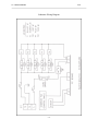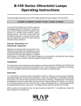
1
Ultraviolet Crosslinkers
Operating Instructions
and Service Manual
IMPORTANT: Please read these instructions before operating your UVP UV
Crosslinker to familiarize yourself with its operation.
81-0112-01 Rev C
UV CROSSLINKERS
UVP
CONTENTS
1.
Introduction
1
2.
Important Safety Information
1
3.
Description and Specifications
1
4.
Operation
3
5.
Applications
6
6.
Maintenance, Care and Cleaning
7
7.
Changing the UV Wavelength
8
8.
Calibration Procedure
10
9.
Replacement Parts
12
10. General Servicing Procedures
Schematic Diagram
13
19
UV CROSSLINKERS
1.
UVP
INTRODUCTION
UVP Crosslinkers offer researchers an instrument to quickly, safely and efficiently expose
samples to a controlled amount of ultraviolet radiation. CL-1000 series features a lay-down
type drawer while the CX-2000 has a pull-out drawer. Exposure of samples to UV provides for
the following:
•
•
•
•
•
•
•
Crosslinking of DNA or RNA to nitrocellulose, nylon or reinforced nitrocellulose.
PCR sample contamination control.
Photoniking of DNA
Testing RecA function
Rapid site mapping
UV sterilization and sanitization
UV curing
The crosslinkers are designed to measure and control the ultraviolet (UV) radiation within the
exposure chamber. A unique UV sensor continually measures the UV energy and automatically
adjusts to variations in UV intensity that occurs as the UV tubes age. This same UV sensor
feedback measurement system allows you to set UV sample exposure, which automatically
deactivates the UV sources when the set UV energy dose has been achieved.
2.
IMPORTANT SAFETY INFORMATION
Ultraviolet Crosslinkers are a powerful source of ultraviolet radiation. Even though they are not
easily accessible, do not attempt to disengage or override the internal safety interlocks.
Exposure to the UV radiation may result. If the UV sources remain on when the door is open,
the unit is malfunctioning and use should be discontinued until the unit is serviced. Do not
expose unprotected eyes or skin to UV radiation. Always disconnect the UV Crosslinker from
its electrical supply before servicing.
3.
DESCRIPTION AND SPECIFICATIONS
The dimensions of the CL-1000 Series UV Crosslinkers:
External: 8.75"H x 13.75"D x 15.75"W (22.2 x 34.9 x 40.0cm)
Interior chamber:
5"H x 12"D x 10"W (12.7 x 30.5 x 25.4cm)
Weight:
15.5 lbs. (7.5 kg)
Ultraviolet sources:
5 x 8 watt UV dual bipin discharge type tubes
CL-1000 Model:
254nm UV
CL-1000L Model:
365nm UV
CL-1000M Model:
302nm UV
CX-2000 Crosslinker
External:
Internal Chamber:
254nm UV
13.7D x 15.6W x 8.75H in. (348 x 396 x 222 mm)
11.3D x 11.4W x 3H in. (305 x 254 x 127 mm)
-1-
UV CROSSLINKERS
UVP
Features
•
•
•
•
•
•
•
•
•
•
•
•
Microprocessor controlled/UV sensor feedback system
Multiple set functionspreset UV energy exposure
preset UV time exposure
user set UV energy exposure
user set UV time exposure
Maximum UV energy exposure setting of 999,900 microjoules per cm2
Maximum UV time exposure setting of 999.9 minutes
Internal safety interlock
Large LED readout
Tactile membrane switch keypad
UV blocking viewing window
Large interior UV exposure chamber
Dual safety fused
Removable power cord
Laydown type door
Electrical
Part No.
Nominal Voltage/Hertz/Amp
CL-1000 Shortwave Crosslinker
95-0174-01
115V/60Hz/0.7A
95-0174-02
230V/50Hz/0.7A
95-0174-03
100V/50-60Hz/0.8A
CL-1000L Longwave Crosslinker
95-0228-01
115V/60Hz/0.7A
95-0228-02
230V/50Hz/0.7A
95-0228-03
100V/50-60Hz/0.8A
CL-1000M Midrange Crosslinker
95-0230-01
115V/60hz/0.7A
95-0230-02
230V/50Hz/0.7A
95-0230-03
100V/50-60Hz/0.8A
CX-2000 Shortwave Crosslinker
95-0339-01
115V/60Hz/0.7A
95-0339-02
230V/50Hz/0.7A
95-0339-03
100V/50-60Hz/0.8A
-2-
UV CROSSLINKERS
4.
UVP
OPERATION
1.
Place the crosslinker on a level work surface. Be sure there is enough room in front for
the door to open easily.
2.
Plug the female end of the power cord into the crosslinker.
3.
Plug the male end of the power cord into a properly grounded electrical outlet. The
proper operating voltage of the crosslinker is found on the product information label.
Note: For 230V models, or those requiring special power cord connectors, ensure that the
proper configuration of the male connector or the plug has been properly connected to the
power cord.
4.
Turn the On/Off switch to the ON position. Note: WHEN TURNED ON THE
CROSSLINKER DEFAULTS TO THE LAST USED UV EXPOSURE SETTING.
5.
The last UV exposure setting will now be displayed on the LED and the last function
setting will be noted by glowing red spot(s) on the display panel.
6.
Place your sample requiring exposure into the chamber.
7.
The UV Crosslinker can be operated on the following settings:
A. Preset ultraviolet energy exposure setting
Push the PRESET and then ENERGY on the tactile touchpad. The red light at each
position should now be lit and the preprogrammed UV exposure setting of 120,000
microjoules per cm² displayed in the LED as 1200. Note: THE LED DISPLAYS
1200. THIS MUST BE MULTIPLIED BY 100 TO OBTAIN THE EXPOSURE.
Push START. After a slight delay to energize the UV tubes, the LED will begin to
countdown. The unit automatically stops at the end of the exposure cycle and will
beep FIVE times. Exposure is now complete.
NOTE: Though the PRESET UV EXPOSURE SETTING is factory set at
120,000 microjoules per cm², it is possible to change this if necessary, as follows:
Push and hold the PRESET on the tactile touchpad until you hear an audible signal
then push ENERGY also on the touchpad.
Set your new Preset UV exposure by pushing the numbers on the touchpad.
-3-
Remember: THE LED DISPLAY MUST BE MULTIPLIED BY 100 TO OBTAIN
THE PROPER EXPOSURE SETTING.
UV CROSSLINKERS
UVP
The new setting will appear on the LED display.
Push ENTER on the touchpad.
The new setting is now installed.
B.
Preset ultraviolet time exposure
Push PRESET and then TIME on the tactile touchpad. The red light at each
position should now be lit and the preprogrammed UV exposure time of 2 minutes
should be displayed in the LED.
Push START on the touchpad. After a slight delay to energize the UV tubes, the
LED will begin to countdown. NOTE: THE TIME EXPOSURE IS SET IN
MINUTES AND TENTHS OF A MINUTE.
The unit will automatically stop at the end of the exposure cycle and will beep five
times. Exposure is now complete.
Information: Though the PRESET ULTRAVIOLET TIME EXPOSURE is
factory set to 2 minutes, it is possible to change this if necessary, as follows:
Push and hold the PRESET on the touchpad until you hear an audible signal, then
push TIME.
Set your new PRESET UV TIME EXPOSURE by pushing the numbers on the
tactile touchpad. The new setting will appear on the LED display.
Push ENTER and the new setting will be installed.
C. User set UV energy exposure
Sometimes it may be necessary for you to set your own standards for exposure. This
is easily accomplished as follows:
Push the ENERGY on the tactile touchpad then set your energy exposure
requirements by pushing the numbers on the touchpad.
The energy exposure settings should now be displayed on the LED in flashing mode.
-4-
REMEMBER: YOUR ENERGY EXPOSURE SETTINGS DISPLAYED MUST
BE MULTIPLIED BY 100. If settings are correct, push ENTER on the touchpad.
UV CROSSLINKERS
UVP
Push START on the touchpad. After a slight delay to energize the UV tubes, The
LED will begin to countdown. the unit will stop automatically at the end of the
exposure cycle and will beep five times. Exposure is now complete.
D. User set UV time exposure
Setting your own UV time exposure can be achieved as follows:
Push the TIME on the tactile touchpad and then set your requirements by pushing
the numbers. Your time exposure settings will be displayed on the LED in flashing
mode. REMEMBER THAT YOUR TIME EXPOSURE SETTINGS ARE SET IN
MINUTES AND TENTHS OF A MINUTE. If your settings are correct, push
ENTER on the tactile touchpad.
Push START.
After a slight delay to energize the UV tubes, the LED will begin to countdown. The
unit will stop automatically at the end of the exposure cycle and will beep five times.
Exposure is now complete.
8.
At the end of the exposure cycle, simply open the door and remove your sample.
9.
Operational Notes:
A. To abort an exposure, press STOP on the tactile touchpad. The LED will display the
remaining exposure.
B.
To restart an aborted exposure, press START on the touchpad. The exposure will
continue from the point at which the exposure was aborted.
C.
To reset an aborted exposure, press the RESET. The LED and touchpad will return
to the used last setting.
D. The unit will not operate with the door open. Opening the door during a cycle aborts
the cycle. Reclosing the door will reset the cycle to the last entered cycle used. To
restart, press the START key.
-5-
UV CROSSLINKERS
5.
UVP
APPLICATIONS
The Crosslinker is a multi-purpose ultraviolet exposure instrument for use in the laboratory. A
wide variety of applications for ultraviolet radiation exist in the laboratory.
A. UV crosslinking of DNA and RNA by covalently binding nucleic acids to transfer
membranes nitrocellulose, nylon or nylon-reinforced nitrocellulose membranes after
Northern, Southern, slot or dot blotting.
The PRESET ULTRAVIOLET EXPOSURE SETTING is factory set to a UV dose of 120,000
microjoules per cm² for this laboratory purpose. This setting has been found to be the optimal
dose for DNA retention and hybridization-signal sensitivity.
B.
C.
D.
E.
F.
G.
H.
Nicking ethidium-bromide stained DNA in Agarose Gels
Gene Mapping for creating cleavage-inhibiting thymine dimers
Testing RecA function
Ultraviolet Sterilization
Elimination of PCR contamination
UV Curing
Fluorescence of materials
Further Applications can be achieved with the Crosslinkers by changing the ultraviolet
wavelength (see Section 7 Changing the wavelength).
-6-
UV CROSSLINKERS
6.
UVP
MAINTENANCE, CARE AND CLEANING OF THE CROSSLINKER
The UVP UV Crosslinker is built to provide you with trouble-free operation. To ensure correct
service:
NOTE: ALWAYS UNPLUG UNIT FROM ELECTRICAL SUPPLY BEFORE CLEANING
OR DRYING.
1.
Wipe ANY water from inside and outside the unit with a soft cloth or sponge.
2.
Use soap and water with a soft cloth or sponge to clean the unit.
3.
Do not allow chemicals to remain on unit surfaces.
4.
Never clean unit with abrasive pads or cleaners.
5.
Never clean unit with acetone or chloroform.
6.
Clean the UV sensor regularly with a soft cloth and alcohol.
UVP offers technical support for all of its products. If you have any questions about product
use, operation or repair, please contact UVP Customer Service at the following numbers:
Corporate Headquarters:
UVP, Inc.
2066 W. 11th Street,
Upland, CA 91786
TOLL FREE USA (800) 452-6788
PHONE: (909) 946-3197
FAX:
(909) 946-3597
E-MAIL: [email protected]
European Operations:
Ultra-Violet Products Ltd.
Unit 1, Trinity Hall Estate
Nuffield Road
Cambridge CB4 1TG United Kingdom
PHONE: +44(0)1223 420022
FAX:
+44(0)1223 420561
E-MAIL: [email protected]
NOTE: A Returned Goods Authorization (RGA) number must be obtained before returning any
item to UVP.
-7-
UV CROSSLINKERS
7.
UVP
CHANGING THE UV WAVELENGTH
A UV Crosslinker is purchased with shortwave, longwave or midrange tubes. However, if user
requirements and applications change, the Crosslinkers provide you with the unique ability to
change the ultraviolet wavelength and recalibrate the UV sensor and microprocessor to the new
UV wavelength. This is accomplished by purchasing FIVE tubes of the NEW UV wavelength
and the proper UVP calibration sensor.
TUBE P/N WAVELENGTH
34-0006-01
34-0042-01
34-0007-01
UVP CALIBRATION SENSOR P/N
365 nm Longwave
302 nm Midrange
254 nm Shortwave
97-0016-02
97-0016-04
97-0016-01
UVX-36 Longwave
UVX-31 Midrange
UVX-25 Shortwave
UV Wavelength Calibration Procedure
1.
After disconnecting the unit from the electrical supply, install the FIVE NEW
WAVELENGTH Tubes as directed in Section 9A. (Changing tubes).
2.
Plug the corresponding UV calibration sensor into the TOP HOLE just inside of the door
at the upper right.
3.
Place the UV calibration sensor in the middle of the floor of the exposure chamber.
4.
Close the crosslinker door.
5.
Invoke the calibration mode of the Crosslinker by pushing/holding down STOP on the
tactile touchpad and turning the power to the unit ON.
6.
A sequence of tones will be heard from the Crosslinker and a 180 second count will
display on the LED when the calibration procedure has started.
7.
No calibration occurs during this 180-second period. This period allows a UV tube warmup and stabilization period.
8.
Upon completion of the 180-second period, measurements are automatically made with
the UV calibration sensor and the crosslinker sensor. These measurements are compared
to limits of acceptability and/or if sensor operation is within range.
9.
If sensor readings are unacceptable, an error code (01, 02, 03 or 04) will flash on the LED
Press any key to stop.
-8-
10. Check all connections and redo calibration. If the same error message appears, call UVP.
UV CROSSLINKERS
UVP
11. The previous calibrated operation of the crosslinker will continue following any
unsuccessful recalibration. Replace the new UV wavelength tubes with the previously
removed old wavelength tubes.
12. Successful recalibration to the NEW UV wavelength changes the values in the
microprocessor and numeric setting value is displayed on the LED. To return to original
or another wavelength the proper UV calibration sensor is needed.
-9-
UV CROSSLINKERS
8.
UVP
CROSSLINKER CALIBRATION PROCEDURE
Equipment necessary:
Chart recorder
Two probes with banana plug adapters
One radiometer with UVX-25 calibrated sensor
Cable with banana plug and jack adaptor to connect radiometer to chart-recorder
Power source (100V, 115V or 230V)
Procedure:
1.
Connect the crosslinker to the power source. Do not turn on the unit at this time.
2.
Connect the testing probes to the chart recorder and to the crosslinkers PCB as follows:
PEN 1 (red) to the right side of R7
PEN 2 (blue) to the right side of R6
Ground both pens at the lower part of R2
Note: while connecting these probes, the switches for both pens on the chart recorder
should be on ZERO position to avoid possible damage to the recorder.
3.
Place the UVX-25 sensor inside the crosslinker at the center and slide it through the upper
hole of the inner chassis. Plug the sensor into the PCB's jack.
4.
Select 5V scale for both pens. Turn the chart recorder on.
5.
Select a speed of 15mm/min.
6.
Switch both pens to MEASURE and DOWN positions so they can touch the chart paper.
7.
Adjust the ZERO position for both pens.
8.
Press the CHART DRIVE switch.
- 10 -
UV CROSSLINKERS
9.
UVP
Run the Crosslinker in calibration mode by depressing the STOP/RESET button and
turning the power switch on at the same time. At this point, both pens should start
recording information on paper. Sometimes either pen will record zero information
regardless of the lights in the crosslinker being on, if this is the case, check for bad
connections.
10. During calibration, check the voltage levels on both pens. By adjusting the
potentiometers on the PBC, adjust the values for U4 and U5. Depending on the voltage
used, from past units it has been found that the optimum values for these levels are:
VOLTAGE
115V
220V
100V
RANGE FOR U4
3.3-3.5V
3.5-3.7V
2.5-2.7V
RANGE FOR U5
2.1-2.3V
1.7-2.0V
2.6-2.9V
11. When the calibration cycle is finished, move both pens to UP and ZERO positions.
12. Unplug the UVX-25 sensor and disconnect the probe for PEN 2.
13. At this point, it is necessary to check the energy levels of the crosslinker to see if the unit
was calibrated properly. Slide the UVX-25's cable through the lower hole of the inner
chassis and plug it into the radiometer.
14. Connect the radiometer to PEN 2 of the chart recorder.
15. Select 1V scale for PEN 2 and a speed of 60mm/min.
16. Lower both pens, turn the CHART DRIVE switch on, change the pens' switches to
MEASURE position and adjust for zero level.
17. Select an energy level of 600 Joules on the crosslinker and press the START button.
18. When the cycle is completed, repeat for 1,200 and 2,000 Joules levels.
19. Calculate the actual amount of energy and compare it with the energy selected. They
should be within a range of +/- 10%. If this is not the case, adjustments should be made
during a repeat calibration. Repeat all the above procedures until the actual levels are
within range.
20. When the three levels of energy are acceptable, disconnect the sensor and the chart
recorder from the Crosslinker. At this point, the unit is ready to be tested.
- 11 -
UV CROSSLINKERS
9.
UVP
REPLACEMENT PARTS AND SERVICING PROCEDURES
PART NO.
A.
OPERATIONS WITHOUT REMOVING THE TOP COVER
Changing tubes
B.
OPERATIONS WITH TOP COVER REMOVED
Replacement of tube holders
Replacement of starters
Replacement of starter holders
Replacement of fuse holders
Replacement of main connector
Replacement of main switch
Replacement of UV sensor
Replacement of PCB
Replacement of membrane panel
5 x 34-0007-01
5 x 36-0003-01
5 x 53-0001-02
or 53-0132-01
5 x 36-0005-01
2 x 56-0023-02
55-0105-01
53-0134-01
39-0006-01
57-0014-01
53-0133-01
C.
OPERATIONS WITH THE INTERNAL CHASSIS ASSEMBLY REMOVED
Replacement of reflector
16-0095-01
D.
OPERATIONS WITH REFLECTOR REMOVED
Replacement of micro-switch
Replacement of ballasts
E.
Replacement of magnetic door holders
53-0072-01
5 x 42-0005-03 100V
5 x 42-0005-04 230V
5 x 42-0005-01 115V
2 x 67-0019-01
GENERAL ITEMS
Changing fuses
Changing plastic feet
2 x 56-0022-02
4 x 72-0004-01
- 12 -
UV CROSSLINKERS
UVP
10. GENERAL SERVICING PROCEDURES
A. Operations Without Removing The Top Cover
Changing the Tubes
It is recommended to change all FIVE 8-Watt 254nm UV tubes at the same time. The unit does
not require recalibration if you are replacing the old sources with new sources of the same
wavelength.
1.
Purchase five tubes from UVP.
2.
Unplug the unit from the electrical supply.
3.
Reach up to the inside top of unit and carefully rotate each UV tube a 1/4 to 1/3 turn and
pull gently downward.
4.
After removing all five old tubes, carefully install the five new tubes.
5.
Dispose of the old UV tubes properly.
B.
Operations With Top Cover Removed
Removal of top cover
Remove the four screws located on the two sides of the unit (2 each side).
Remove the cover, moving in an upwards direction and store safely.
All of the operations below are described as taking place within the unit unless otherwise
stated.
Replacement of tube holders
1.
Open front door on unit.
2.
Locate tube holders to be changed. (These will be seen at the front and back of the internal
chassis assembly - 5 at the front and 5 at the back).
3.
Loosen and remove screw on the tube holder(s). This screw is located in the main
chamber-at the top and just in front of the tube holder(s).
4.
The tube should now be loose.
- 13 -
UV CROSSLINKERS
UVP
5.
Cut all of the cable ties coming from the tube holder following the two wires from the
tube holder to where it terminates. Note: there will be two different termination points for
each tube holder. Once this has been located, cut the wires (marking them to ensure easy
replacement).
6.
The tube holder(s) can now be removed by pushing the holder into the main chamber and
feeding the wires through the cut-out.
7.
Replace tube holder(s). (Part number 36-0003-01)
8.
In order to refit the tube holder, reverse the above procedure using butt crimps to
reconnect the wires.
Note: If more than one tube holder is to be replaced, the wiring schematic diagram may be of
assistance.
Replacement of starters
1.
Locate the starter to be changed. These are positioned in a vertical row on the right hand
side of the internal chassis assembly.
2.
Turn starter(s) 30 degrees anti-clockwise and then pull out of the holder.
3.
Reverse above procedure with recommended starter.
Replacement of starter holder
1.
Locate the starter holder to be changed. It is located on the right hand side of the internal
chassis assembly.
2.
Lever off the starter holder using a flat bladed screwdriver. The holder should now be
loose.
3.
Replace unit (part number 36-0005-01). This is achieved by first loosening the internal
reflector which is held in place with eight screws. The screws can be located in the
chamber of the crosslinker - two on the left, two on the right and four on the top of the
chamber.
4.
To replace the starter holder first push the center of the two black spigots, which hold the
starter holder (x2) away from you i.e. towards the crosslinker chamber. As the reflector
has been loosened, this should be done fairly easily with a small, flat-bladed screwdriver.
5.
The starter can now be relocated.
- 14 -
UV CROSSLINKERS
UVP
6.
To secure the starter holder, place the holder in your right hand and with your left hand in
the chamber, press the now loosened reflector adjacent to the holder inwards. This will
push the black spigots inwards thereby securing the starter holder.
7.
Re-fit the reflector.
Replacement of fuse holders
These are located at the back of the unit just above the mains connector. There are two fuses in
separate holders. Replacement is the same for both.
1. Cut back the heat shrink on the two wires.
2. Unsolder both connections and pull from the holder.
3. Unscrew the nylon nut and push the holder out through the back of the unit.
4. To replace-reverse the above procedure.
Replacement of main connector
This is located at the back of the unit below the fuse holders.
1. Cut back the heat shrink on the three wires.
2. Unsolder the three connections and pull from connector.
3. Release main connector by holding the nuts with a spanner and then on the outside back of
the unit, release the two screws one at a time (using a screwdriver). The main connector
should now be loose.
4. To replace-reverse the above procedure.
Replacement of main switch
This is located on the front panel below the membrane pad.
1. Remove the wires noting their position.
2. Remove the switch by pushing it out from the back towards the rear of the front panel.
3. Push in the new switch and re-connect.
- 15 -
UV CROSSLINKERS
UVP
Replacement of UV sensor
UVP recommends returning the Crosslinker to the UVP factory for service. This is located on
the right hand side of the internal chassis assembly at the back near the base.
1.
Unplug the sensor connector from the PCB board marked J2.
2.
Release the sensor by removing the location screw with a screwdriver and holding the nut
inside the main chamber with a spanner. Pull sensor clear.
3.
For replacement, reverse the above procedure.
Note: The crosslinker will now need recalibration-see section 8.
Replacement of PCB
The main PCB is located on the right of the unit directly behind the front membrane panel.
1. Disconnect the ribbon connector J4. See wiring diagram for position.
2. Unscrew the four screws located at the top and bottom. Note: if the membrane panel needs to
be replaced, it should be replaced now. See next paragraph.
3. For replacement-reverse the above procedure.
Replacement of membrane panel
Located on the front panel.
1. Carry out the above procedure-replacement of PCB.
2. Peel off membrane after first marking the position with a pencil, and feed out the ribbon
cable.
3. Replace membrane pad.
Note: Marking the position of the membrane will ensure that the new part will be in the exact
position as fitted from the factory.
- 16 -
UV CROSSLINKERS
UVP
C. Operations With The Internal Chassis Assembly Removed
Removal of the assembly
1. Release the wire to the micro switch located on the bottom left internal chassis assembly.
2. Release the main power cable to ballasts - black wire with connector (color red).
3. Release all eight nuts positioned four on top of the unit, two sets on either side of the unit.
See diagram for positions.
4. Slide unit out from the main frame.
Replacement of reflector
The reflector is located inside of the internal chassis assembly.
1. Release the eight screws-four on the top and two on either side of the unit.
2. Pull the reflector out towards the front of the unit. Note: for cleaning the reflector, refer to
Section 6 for maintenance/care/cleaning of the crosslinker.
3. For replacement-reverse the above procedure.
D. Operations With The Reflector Removed
Replacement of ballasts
The ballasts are fitted to the right hand side of the internal chassis assembly.
1.
Select the ballast(s) which need to be replaced.
2.
Cut the tie wraps to locate the ballast electrical connectors.
3.
Cut these wires and mark positions.
4.
Re-fit new ballasts using M4 posidrive screws with shake proof and plain washers with a
nut as fitted on the diagram.
- 17 -
UV CROSSLINKERS
E.
UVP
General Items
Changing fuses
The fuses are located on the back panel and are marked with a self-adhesive sticker.
1. Turn fuse cap 15 degrees anti-clockwise.
2. Pull fuse and cap from the holder.
3. Pull fuse from the cap.
4. Replace the fuse.
5. Replace fuse cap and fuse into holder and turn 15 degrees clockwise.
Changing plastic feet
The feet are fitted to the bottom of the cabinet. They are removed by unscrewing the screw
mounted inside each foot.
- 18 -
UV CROSSLINKERS
UVP
Schematic Wiring Diagram
- 19 -
UV CROSSLINKERS
UVP
Internet: www.uvp.com
Corporate Headquarters: UVP, Inc.
2066 W. 11th Street
Upland, CA 91786
Tel: (800)452-6788 or (909)946-3197
Fax: (909)946-3597 / E-Mail: [email protected]
European Operations:
Ultra-Violet Products Ltd.
Unit 1, Trinity Hall Estate, Nuffield Road
Cambridge CB4 1TG United Kingdom
Tel: +44(0)1223 420022
Fax: +44(0)1223 420561 / E-Mail: [email protected]