1
Operating Instructions
Differential pressure transmitter DPT-10
Metallic measurement diaphragm
Foundation Fieldbus
Differential pressure transmitter DPT-10
Contents
Contents
1 About this document
1.1 Function............................................................................................................................ 4
1.2 Target group...................................................................................................................... 4
1.3 Symbolism used................................................................................................................ 4
2 For your safety
2.1 Authorised personnel........................................................................................................ 5
2.2 Appropriate use................................................................................................................. 5
2.3 Warning about incorrect use.............................................................................................. 5
2.4 General safety instructions................................................................................................ 5
2.5 Safety label on the instrument........................................................................................... 5
2.6 CE conformity.................................................................................................................... 6
2.7 Fulfillment of NAMUR recommendations.......................................................................... 6
2.8 Safety instructions for oxygen applications........................................................................ 6
3 Product description
3.1 Configuration..................................................................................................................... 7
3.2 Principle of operation........................................................................................................ 8
3.3 Adjustment...................................................................................................................... 11
3.4 Packaging, transport and storage.................................................................................... 11
4Mounting
4.1 General instructions to use the instrument...................................................................... 13
4.2 Instructions for oxygen applications................................................................................ 14
4.3 Mounting and connection instructions............................................................................. 14
4.4 Measurement setup flow................................................................................................. 18
4.5 Measurement setup level................................................................................................ 21
4.6 Measurement setup density and interface....................................................................... 25
4.7 Measurement setup differential pressure........................................................................ 27
4.8 Mounting external housing.............................................................................................. 29
4.9 Installation control........................................................................................................... 30
5 Connecting to power supply
5.1 Preparing the connection................................................................................................ 31
5.2 Connection procedure..................................................................................................... 32
5.3 Single chamber housing.................................................................................................. 33
5.4 Wiring plan, double chamber housing............................................................................. 33
5.5 Double chamber housing Ex d........................................................................................ 36
5.6 Version IP 66/IP 68, 1 bar................................................................................................ 37
5.7 Switch-on phase............................................................................................................. 38
6 Adjustment with the display and adjustment module
6.1 Short description............................................................................................................. 39
6.2 Insert display and adjustment module............................................................................. 39
6.3 Adjustment system.......................................................................................................... 40
6.4 Parameter description..................................................................................................... 41
6.5 Menu schematic.............................................................................................................. 49
6.12 Saving the parameter adjustment data............................................................................ 52
7 Setup with the adjustment program AMS™
7.1 Parameter adjustment with AMS™................................................................................. 53
2
WIKA Operating Instructions - Differential pressure transmitter DPT-10
Contents
8Setup
8.1 Select the mode.............................................................................................................. 54
8.2 Flow measurement.......................................................................................................... 54
8.3 Level measurement......................................................................................................... 56
8.4 Density and interface measurement................................................................................ 60
8.5 Differential pressure measurement................................................................................. 60
9 Maintenance and fault rectification
9.1 Maintenance................................................................................................................... 63
9.2 Rectify faults.................................................................................................................... 63
9.3 Instrument repair............................................................................................................. 64
10 Dismounting
10.1 Dismounting steps.......................................................................................................... 65
10.2 Disposal.......................................................................................................................... 65
11 Supplement
11.1 Technical data................................................................................................................. 66
11.2 Information on Foundation Fieldbus................................................................................ 74
11.3 Dimensions..................................................................................................................... 78
Safety instructions for Ex areas
Please note the Ex-specific safety information for installation and operation in Ex areas. These safety instructions are part of the operating
instructions manual and come with the Ex-approved instruments.
Editing status: 2013-07-11
WIKA Operating Instructions - Differential pressure transmitter DPT-10
3
1 About this document
1 About this document
1.1 Function
This operating instructions manual provides all the information you
need for mounting, connection and setup as well as important instructions for maintenance and fault rectification. Please read this information before putting the instrument into operation and keep this manual
accessible in the immediate vicinity of the device.
1.2 Target group
This operating instructions manual is directed to trained specialist
personnel. The contents of this manual should be made available to
these personnel and put into practice by them.
1.3 Symbolism used
Information, tip, note
This symbol indicates helpful additional information.
Caution: If this warning is ignored, faults or malfunctions can result.
Warning: If this warning is ignored, injury to persons and/or serious
damage to the instrument can result.
Danger: If this warning is ignored, serious injury to persons and/or
destruction of the instrument can result.
Ex applications
This symbol indicates special instructions for Ex applications.
•
→
1
List
The dot set in front indicates a list with no implied sequence.
Action
This arrow indicates a single action.
Sequence of actions
Numbers set in front indicate successive steps in a procedure.
Battery disposal
This symbol indicates special information about the disposal of batteries and accumulators.
4
WIKA Operating Instructions - Differential pressure transmitter DPT-10
2 For your safety
2 For your safety
2.1 Authorised personnel
Mount and set up the pressure transmitter only if you know the applicable national regulations and have the appropriate qualification. You
must be aquainted with the regulations and instructions for hazardous areas, measurement and control technology as well as electrical
circuits because the pressure transmitter is "electrical equipment"
according to EN 50178. Depending on the application conditions, it
is necessary that you have appropriate knowledge, e.g. concerning
corrosive products or high pressure.
2.2 Appropriate use
DPT10 is a differential pressure transmitter for measurement of flow,
level, differential pressure, density and interface.
You can find detailed information on the application range in chapter
"Product description".
Operational reliability is ensured only if the instrument is properly
used according to the specifications in the operating instructions
manual as well as possible supplementary instructions.
For safety and warranty reasons, any invasive work on the device
beyond that described in the operating instructions manual may be
carried out only by personnel authorised by the manufacturer. Arbitrary conversions or modifications are explicitly forbidden.
2.3 Warning about incorrect use
Inappropriate or incorrect use of the instrument can give rise to
application-specific hazards, e.g. vessel overfill or damage to system
components through incorrect mounting or adjustment.
2.4 General safety instructions
This is a high-tech instrument requiring the strict observance of standard regulations and guidelines. The user must take note of the safety
instructions in this operating instructions manual, the country-specific
installation standards as well as all prevailing safety regulations and
accident prevention rules.
The instrument must only be operated in a technically flawless and
reliable condition. The operator is responsible for trouble-free operation of the instrument.
During the entire duration of use, the user is obliged to determine the
compliance of the necessary occupational safety measures with the
current valid rules and regulations and also take note of new regulations.
2.5 Safety label on the instrument
The safety approval markings and safety tips on the device must be
observed.
WIKA Operating Instructions - Differential pressure transmitter DPT-10
5
2 For your safety
2.6 CE conformity
The device fulfills the legal requirements of the applicable EC guidelines. By affixing the CE marking, we confirm successful testing of the
product.
2.7 Fulfillment of NAMUR recommendations
The device fulfills the requirements of the applicable NAMUR recommendations.
2.8 Safety instructions for oxygen applications
For instruments in oxygen applications the special instructions in
chapters "Storage and transport", "Mounting" as well as "Technical
data" under "Process conditions"must be noted. Furthermore the valid
national regulations, implementation instructions and memorandums
of the professional assocations must be noted.
6
WIKA Operating Instructions - Differential pressure transmitter DPT-10
3 Product description
3 Product description
Scope of delivery
3.1 Configuration
The scope of delivery encompasses:
•
•
•
•
Constituent parts
DPT10 differential pressure transmitter
Depending on the version, ventilation valves and/or screw plugs
(details see chapter "Dimensions")
Optional accessory
Documentation
–– this operating instructions manual
–– Test certificate for pressure transmitters
–– Operating instructions manual "Display and adjustment module" (optional)
–– Ex-specific "Safety instructions" (with Ex versions)
–– if necessary, further certificates
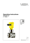
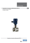
The following illustration shows the components of DPT10:
1
2
3
+ –
Fig. 1: DPT10 in basic version
1 Housing cover, optionally with integrated display and adjustment module
2 Housing with electronics
3 Process component with measuring cell
The components are available in different versions.
The nameplate contains the most important data for identification and
use of the instrument:
WIKA Operating Instructions - Differential pressure transmitter DPT-10
7
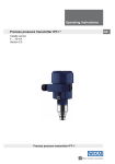
3 Product description
1
2
3
4
10
5
6
7
8
9
Fig. 2: Layout of the type label (example)
1 Instrument type
2 Field for approvals
3 Measuring range
4 Signal output/Supply voltage
5 Process pressure - Process temperature
6 Seal material
7 Product code
8 Order number
9 Serial number of the instrument
10 ID numbers, instrument documentation
Application area
3.2 Principle of operation
DPT10 is a differential pressure transmitter for measurement of flow,
level, differential pressure, density and interface. Measured products
are gases, vapours and liquids.
Flow measurement
Q ~ ∆p
+
p1
Q
–
p2
Q ~ ∆p
+
p1
–
p2
Q
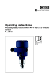
1
2
Fig. 3: Flow measurement with DPT10 and DP flow element, Q = flow, Δp = differential pressure, Δp = p1 - p2
1 Orifice
2 Pitot tube
8
WIKA Operating Instructions - Differential pressure transmitter DPT-10
3 Product description
Level measurement
–
h
–
∆p
h= ρ g
+
+ –
+
1
2
3
Fig. 4: Level measurement with DPT10. Δp = differential pressure, ρ = density of
the medium, g = acceleration of gravity
1 Basic version with effective pressure lines
2 Version with flange chemical seal
3 Version with capillaries and cell chemical seals
Differential pressure measurement
2
+
1
Fig. 5: Differential pressure measurement with DPT10
1Filter
2DPT10
Density measurement
h
–
=
∆p
h g
+
1
Fig. 6: Density measurement with DPT10, h = defined mounting distance, Δp =
differential pressure, ρ = density of the medium, g = acceleration of gravity
1DPT10
WIKA Operating Instructions - Differential pressure transmitter DPT-10
9
3 Product description
h
Interface measurement
3
–
2
+
1
Fig. 7: Interface measurement with DPT10
1DPT10
2 Liquid with higher density
3 Liquid with lower density
Functional principle
A metallic measuring cell is used as sensor element. The process
pressures are transmitted via the separating diaphragms and filling
oils to a resistance measuring bridge (semi-conductor technology).
The difference between the acting pressures generates a change in
the bridge voltage. This change is measured, further processed and
converted into a corresponding output signal.
The markings "+" and "-" on the process component in chapter
"Mounting and connection instructions" must therefore be noted when
connecting to the process. The pressure acting on "+" goes positive,
the pressure acting on "-" goes negative into the calculation of the
pressure difference.
The configuration of the measuring cells differs depending on the
measuring range:
1
2
p1
3
4
p2
5
Fig. 8: Metallic measuring cell 10 mbar and 30 mbar - p1 and p2 process pressures
1
2
3
4
5
10
Measuring element
Silicone diaphragm
Separating diaphragm
Filling oil
Integrated overvoltage arrester
WIKA Operating Instructions - Differential pressure transmitter DPT-10
3 Product description
1
p1
2
3
4
p2
Fig. 9: Metallic measuring cell from 100 mbar - p1 and p2 process pressures
1
2
3
4
Power supply and bus
communication
Power is supplied via the H1 Fieldbus. A two-wire cable according to
Fieldbus specification serves as carrier of both power and digital data
for multiple sensors. This cable can be operated in two versions:
•
•
DD/CFF
Measuring element
Overload diaphragm/Middle diaphragm
Filling oil
Separating diaphragm
via an H1 interface card in the control system and additional power
supply
via a Linking device with HSE (High speed Ethernet) and additional power supply according to IEC 61158-2
The DD (Device Descriptions) and CFF (capability files) necessary
for planning and configuration of your FF (Foundation Fieldbus) communication network are available in the download area of the WIKA
homepage www.wika.com under "Services". The appropriate certificates are also available there. A CD with the appropriate files and
certificates can be ordered by phone from one of the WIKA agencies.
The backlight of the display and adjustment module is powered by the
sensor. Prerequisite is a certain level of operating voltage.
The data for power supply are specified in chapter "Technical data".
3.3 Adjustment
The instrument can be adjusted with the following adjustment media:
•
•
With the display and adjustment module
a configuration tool
The entered parameters are generally saved in DPT10, optionally
also in the indicating/adjustment module.
Packaging
3.4 Packaging, transport and storage
Your instrument was protected by packaging during transport. Its
capacity to handle normal loads during transport is assured by a test
based on ISO 4180.
The packaging of standard instruments consists of environmentfriendly, recyclable cardboard. For special versions, PE foam or PE
foil is also used. Dispose of the packaging material via specialised
recycling companies.
WIKA Operating Instructions - Differential pressure transmitter DPT-10
11
3 Product description
Caution:
Instruments for oxygen applications are sealed in PE foil and provided
with a label "Oxygen! Use no Oil". Remove this foil just before mounting the instrument! See instruction under "Mounting".
Transport
Transport must be carried out in due consideration of the notes on the
transport packaging. Nonobservance of these instructions can cause
damage to the device.
Transport inspection
The delivery must be checked for completeness and possible transit
damage immediately at receipt. Ascertained transit damage or concealed defects must be appropriately dealt with.
Storage
Up to the time of installation, the packages must be left closed and
stored according to the orientation and storage markings on the
outside.
Unless otherwise indicated, the packages must be stored only under
the following conditions:
Storage and transport
temperature
12
•
•
•
•
•
•
•
Not in the open
Dry and dust free
Not exposed to corrosive media
Protected against solar radiation
Avoiding mechanical shock and vibration
Storage and transport temperature see chapter "Supplement Technical data - Ambient conditions"
Relative humidity 20 … 85 %
WIKA Operating Instructions - Differential pressure transmitter DPT-10
4 Mounting
4Mounting
4.1 General instructions to use the instrument
Suitability for the process Make sure that all parts of the instrument coming in direct contact
conditions
with the process, especially the sensor element, process seal and
process fitting, are suitable for the existing process conditions, such
as process pressure, process temperature as well as the chemical
properties of the medium.
You can find the specifications in chapter "Technical data" and on the
nameplate.
Moisture
Use the recommended cables (see chapter "Connecting to power
supply") and tighten the cable gland.
You can give the instrument additional protection against moisture
penetration by leading the connection cable downward in front of the
cable entry. Rain and condensation water can thus drain off. This applies mainly to outdoor mounting as well as installation in areas where
high humidity is expected (e.g. through cleaning processes) or on
cooled or heated vessels.
Ventilation
The ventilation for the electronics housing is realised via a filter element in the vicinity of the cable glands.
1
2
1
Fig. 10: Position of the filter element with single and double chamber housing
1 Filter element for ventilation of the electronics housing
2 Blind plug
Information:
Make sure that the filter element is always free of buildup during
operation. A high-pressure cleaner may not be used for cleaning.
Effective pressure transmitter
DP flow elements are calculated for certain pipeline and operating
data. Therefore, check the pipeline data before installation at the
measuring point and compare the measurement loop number.
Detailed instructions for mounting the DP flow element are stated in
DIN EN ISO 5167 as well as in the instrument documentation from the
respective manufacturer.
Effective pressure lines
You will find general recommendations for the installation of effective
pressure lines in the corresponding national or international standards. When installing effective pressure lines outdoors, consider
applying suitable anti-freeze protection, e.g. tube heating. Install
effective pressure lines with a monotonic downward slope of at least
10 %.
WIKA Operating Instructions - Differential pressure transmitter DPT-10
13
4 Mounting
Vibrations
In case of strong vibrations at the application position, the instrument
version with external electronics should be used.
Temperature limits
Higher process temperatures often mean also higher ambient temperatures for electronics and connection cable. Make sure that the
upper temperature limits stated in chapter "Technical data" for the
environment of the electronics housing and connection cable are not
exceeded.
Oxygen applications
4.2 Instructions for oxygen applications
Oxygen and other gases can be explosive when brought into contact
with oils, grease and plastics, so the following measures must also be
taken:
•
•
All components of the plant, such as e.g. measuring instruments must be cleaned according to the requirements of BAM
(DIN 19247)
Depending on the seal material, certain temperatures and pressures must not be exceeded in oxygen applications, see chapter
"Technical data"
Danger:
Instruments for oxygen applications must be unpacked just before
mounting. After removing the protective cover of the process fitting,
the label "O2" will be visible on the process fitting. Penetration of oil,
grease and dirt should be avoided. Danger of explosion!
Connection plus/minus
side
4.3 Mounting and connection instructions
When connecting the DPT10 to the measurement loop, take note
of the plus/minus side of the process component. The plus side is
marked with a "+", the minus side with a "-" on the process component next to the oval flanges.
+ –
1
2
Fig. 11: Marking for plus/minus side on the process component
1 Plus side
2 Minus side
Mounting arrangement
14
The following illustration shows the elements for a tube mounting and
an example for a mounting arrangement with valve block.
WIKA Operating Instructions - Differential pressure transmitter DPT-10
4 Mounting
1 2
3
4
5
6
7
8
9
10
Fig. 12: Mounting arrangement with tube mounting
1 Strap for tube mounting
2 Mounting bracket
3 Ventilation valve
4 Fixing screws
5DPT10
6 PTFE seal
7 Valve block
8 Oval flange adapter
9 Fixing screws
10 Effective pressure line
Valve blocks
Valve blocks enable the simple installation and setup of the differential
pressure transmitter. They separate the pressure transmitter from the
process side and enable also a check of the measurement loop. They
are available as 3-fold and 5-fold version. The integrated equalization
valve enables a pressure compensation between plus and minus side
during the setup. Thanks to the valve block it is possible to dismount
the DPT10 without interrupting the process. This means higher plant
availability and simpler setup or maintenance.
The 3-fold valve block with flanging on both sides enables a mechanically stable connection between the DPT10 and e.g. the tapping
points or the flange plate of a pitot tube. With the five-fold valve block,
two additional valves allow blowing out the process lines or checking
the DPT10 in installed condition.
Connect 3-fold valve
block
The following illustration shows the connection of the 3-fold valve
block.
WIKA Operating Instructions - Differential pressure transmitter DPT-10
15
4 Mounting
A
A:
3
5
1
2
1
3
4
2
5 4
2
Fig. 13: Connection of a 3-fold valve block
1
2
3
4
5
3-fold valve block, flanging on both sides
16
Process fitting
Process fitting
Inlet valve
Inlet valve
Breather valve
The following illustration shows the connection of the 3-fold valve
block, flanging on both sides.
WIKA Operating Instructions - Differential pressure transmitter DPT-10
4 Mounting
A
A:
3
1
2 5 2
1
3
5 4
4
2
Fig. 14: Connection of a 3-fold valve block, flanging on both sides
1
2
3
4
5
5-fold valve block
Process fitting
Process fitting
Inlet valve
Inlet valve
Breather valve
The following illustration shows the connection of the 5-fold valve
block.
WIKA Operating Instructions - Differential pressure transmitter DPT-10
17
4 Mounting
A
7
A:
9
3 1
2
5
8
2
4 6
3
4
5
1
7
9 8
2
6
Fig. 15: Connection of a 5-fold valve block
1 Process fitting
2 Process fitting
3Check/Ventilate
4Check/Ventilate
5 Valve for checking/ventilating
6 Valve for checking/ventilating
7 Inlet valve
8 Inlet valve
9 Breather valve
In gases
18
4.4 Measurement setup flow
→ Mount DPT10 above the measurement loop so that condensate
can drain off in the process cable.
WIKA Operating Instructions - Differential pressure transmitter DPT-10
4 Mounting
1
2
3
+
–
4
Fig. 16: Measurement setup with flow measurement of gases, connection via
3-fold valve block
1DPT10
2 3-fold valve block
3 Blocking valves
4 Orifice or impact pressure probe
1
2
+
3
Fig. 17: Measurement setup with flow measurement of gases, connection via
3-fold valve block, flanging on both sides
1DPT10
2 3-fold valve block, flanging on both sides
3 Orifice or impact pressure probe
In vapours
1. Mount DPT10 below the measurement loop
2. Mount condensate vessels at the same height with the discharge
socket and at the same distance to DPT10
3. Fill the effective pressure lines to the height of the condensate
vessels before setup
WIKA Operating Instructions - Differential pressure transmitter DPT-10
19
4 Mounting
1
3
2
+
5
4
–
3
5
6
Fig. 18: Measurement setup, flow measurement in vapours
1 Condensate vessels
2 Orifice or impact pressure probe
3 Blocking valves
4DPT10
5 Drain or blow-off valves
6 3-fold valve block
In liquids
When using a 5-fold valve block, the drain or blow-off valves are
already integrated.
1. Mount DPT10 below the measurement loop so that the effective
pressure lines are always filled with liquid and gas bubbles can
bubble up to the process line
2. For measurements in products with solid content such as e.g.
dirty liquids, the installation of separators and drain valves is
recommended to enable collection and removal of debris and
sediment.
3. Fill the effective pressure lines to the height of the condensate
vessels before setup
20
WIKA Operating Instructions - Differential pressure transmitter DPT-10
4 Mounting
1
2
3
+
2
–
4
4
5
5
6
Fig. 19: Measurement setup, flow measurement in liquids
1 Orifice or impact pressure probe
2 Blocking valves
3DPT10
4Precipitator
5 Drain valves
6 3-fold valve block
In open vessels with effective pressure line
4.5 Measurement setup level
1. Mount DPT10 below the lower measurement connection so that
the effective pressure lines are always filled with liquid
2. Minus side is open to the atmospheric pressure
3. When measuring liquids with solid content, the mounting of separators and drain valves is useful to be able to avoid and remove
buildup.
patm
+
min.
4
5
patm 1
2
3
Fig. 20: Measurement setup, level measurement in the open vessel
1DPT10
2 Minus side is open to the atmospheric pressure
3 Blocking valve
4Precipitator
5 Drain valve
WIKA Operating Instructions - Differential pressure transmitter DPT-10
21
4 Mounting
In open vessels with
single chemical seal
1. Mount DPT10 directly to the vessel
2. Minus side is open to the atmospheric pressure
patm
min.
1
+
+ –
patm 2
Fig. 21: Measurement setup, level measurement in the open vessel
1DPT10
2 Minus side is open to the atmospheric pressure
In closed vessels with effective pressure lines
1. Mount DPT10 below the lower measurement connection so that
the effective pressure lines are always filled with liquid
2. Connect minus side always above the max. level
3. For measurements in products with solid content such as e.g.
dirty liquids, the installation of separators and drain valves is
recommended to enable collection and removal of debris and
sediment.
max.
min.
–
+
1
1
2
3
3
4
4
5
Fig. 22: Measurement setup, level measurement in closed vessel
1 Blocking valves
2DPT10
3Precipitator
4 Drain valves
5 3-fold valve block
22
WIKA Operating Instructions - Differential pressure transmitter DPT-10
4 Mounting
In closed vessels with
single chemical seal
1. Mount DPT10 directly to the vessel
2. Connect minus side always above the max. level
3. For measurements in products with solid content such as e.g.
dirty liquids, the installation of separators and drain valves is
recommended to enable collection and removal of debris and
sediment.
1
–
max.
min.
2
+ –
+
3
4
Fig. 23: Measurement setup, level measurement in closed vessel
1 Blocking valve
2Precipitator
3 Drain valve
4DPT10
In closed vessels with
double chemical seal
1. Mount DPT10 below the lower chemical seal
2. The ambient temperature should be the same for both capillaries
Information:
Level measurement is only ensured between the upper edge of the
lower and the lower edge of the upper chemical seal.
–
max.
min.
+
1
Fig. 24: Measurement setup, level measurement in closed vessel
1DPT10
In closed vessels with
1. Mount DPT10 below the lower measurement connection so that
steam layering with effecthe effective pressure lines are always filled with liquid
tive pressure line
2. Connect minus side always above the max. level
WIKA Operating Instructions - Differential pressure transmitter DPT-10
23
4 Mounting
3. The condensate vessel ensures a constant pressure on the
minus side
4. For measurements in products with solid content such as e.g.
dirty liquids, the installation of separators and drain valves is
recommended to enable collection and removal of debris and
sediment.
max.
min.
–
1
2
+
4
5
2
3
5
6
Fig. 25: Measurement setup in closed vessel with superimposed steam
1 Condensate vessel
2 Blocking valves
3DPT10
4Precipitator
5 Drain valves
6 3-fold valve block
In closed vessels with
1. Mount DPT10 directly to the vessel
superimposed steam with 2. Connect minus side always above the max. level
single chemical seal
3. The condensate vessel ensures a constant pressure on the
minus side
4. For measurements in products with solid content such as e.g.
dirty liquids, the installation of separators and drain valves is
recommended to enable collection and removal of debris and
sediment.
24
WIKA Operating Instructions - Differential pressure transmitter DPT-10
4 Mounting
max.
–
1
2
min.
3
+ –
+
5
4
Fig. 26: Measurement setup in closed vessel with superimposed steam
1 Condensate vessel
2 Blocking valve
3Precipitator
4 Drain valve
5DPT10
4.6 Measurement setup density and interface
Density measurement
In a vessel with varying level and homogeneous density distribution,
density measurement with a differential pressure transmitter can be
realized. The connection to the vessel is made via a chemical seal on
two measuring points. To reach a high accuracy, the distance between
these points must be as big as possible. The density measurement is
only ensured with a level above the upper measuring point. If the level
drops below the upper measuring point, the density measurement is
interrupted.
This density measurement functions with open but also with closed
vessels. Make sure that small density changes cause only small
changes to the measured differential pressure. Select a suitable
measuring range.
The density measurement is carried out in the mode level measurement.
1. Mount DPT10 below the lower chemical seal
2. The ambient temperature should be the same for both capillaries
Example for a density measurement:
Distance between the two measurement points: 0.3 m
Min. density: 1000 kg/m³
Max. density: 1200 kg/m³
Measured differential pressure: Δp = ρ • g • h
The min. adjustment is carried out for the differential pressure measured at density 1.0:
Δp = ρ • g • h
= 1000 kg/m³ • 9.81 m/s2 • 0,3 m
= 2943 Pa = 29.43 mbar
WIKA Operating Instructions - Differential pressure transmitter DPT-10
25
4 Mounting
The max. adjustment is carried out for the differential pressure measured at density 1.2:
Δp = ρ • g • h
= 1200 kg/m³ • 9.81 m/s2 • 0.3 m
= 3531 Pa = 35.31 mbar
0,3 m
–
=
∆p
h g
+
Fig. 27: Measurement setup with density measurement
Interface measurement
In a vessel with varying level, an interface measurement with a differential pressure transmitter can be realized. The connection on the
vessel is carried out via a chemical seal on two measuring points.
An interface measurement is only possible if the densities of the two
products remain the same and the interface is always between the
two measuring points. The total level must always be above the upper
measuring point.
This density measurement functions with open but also with closed
vessel.
Example for an interface measurement:
Distance between the two measurement points: 0.3 m
Min. density: 800 kg/m³
Max. density: 1000 kg/m³
The min. adjustment is carried out for the differential pressure occuring with density 0.8:
Δp = ρ • g • h
= 800 kg/m³ • 9.81 m/s • 0.3 m
= 2354 Pa = 23.54 mbar
The max. adjustment is carried out for the differential pressure occuring with density 1.0:
Δp = ρ • g • h
= 1000 kg/m³ • 9.81 m/s • 0.3 m
= 2943 Pa = 29.43 mbar
3. Mount DPT10 below the lower chemical seal
4. The ambient temperature should be the same for both capillaries
26
WIKA Operating Instructions - Differential pressure transmitter DPT-10
4 Mounting
0,3 m
0,8
1,0
–
+
1
Fig. 28: Measurement setup with interface measurement
In gases and vapours
4.7 Measurement setup differential pressure
→ Mount DPT10 above the measurement loop so that condensate
can drain off in the process cable.
1
2
+
3
4
3
4
Fig. 29: Measurement setup with differential pressure measurement between
two pipelines in gases and vapours
1DPT10
2 3-fold valve block
3 Blocking valves
4Pipelines
In vapour and condensate plants
→ Mount DPT10 below the measurement loop so that some condensate can collect in the effective pressure lines.
The ventilation is carried out via the ventilation valves on the instrument, the 5-fold valve block enables blowing out the cables.
WIKA Operating Instructions - Differential pressure transmitter DPT-10
27
4 Mounting
4
3
4
3
1
6
2
5
Fig. 30: Measurement setup with differential pressure measurement between a
vapour and a condensate cable
1 Vapour cable
2 Condensate cable
3 Blocking valves
4 Condensate vessels
5 5-fold valve block
6DPT10
In liquids
1. Mount DPT10 below the measurement loop so that the effective
pressure lines are always filled with liquid and gas bubbles can
bubble up to the process line
2. For measurements in products with solid content such as e.g.
dirty liquids, the installation of separators and drain valves is
recommended to enable collection and removal of debris and
sediment.
2
1
+
3
–
2
4
4
5
5
6
Fig. 31: Measurement setup, flow measurement in liquids
1 E.g. filter
2 Blocking valves
3DPT10
4Precipitator
5 Drain valves
6 3-fold valve block
28
WIKA Operating Instructions - Differential pressure transmitter DPT-10
4 Mounting
When chemical seal
systems are used in all
products
1. Mount chemical seal with capillaries on top or laterally on the
pipeline
2. In vacuum applications: Mount DPT10 below the measurement
loop
3. The ambient temperature should be the same for both capillaries
1
2
+
2
–
3
4
Fig. 32: Measurement setup, differential pressure measurement in gases,
vapours and liquids
1 Chemical seal with bolting
2Capillaries
3 E.g. filter
4DPT10
4.8 Mounting external housing
1. Mark the holes according to the following drilling template
2. Depending on the mounting surface, fasten the wall mounting
plate with 4 screws
90 mm (3.54")
70 mm (2.76")
3 mm
(0.12")
8 mm
(0.32")
93 mm (3.66")
110 mm (4.33")
mm
,5 ")
R3 0.14
(
Fig. 33: Drilling template - wall mounting plate
WIKA Operating Instructions - Differential pressure transmitter DPT-10
29
4 Mounting
Mount the wall mounting plate so that the cable entry of the socket
housing points downward. The socket housing can be displaced by
180° to the wall mounting plate.
4.9 Installation control
Check the following after mounting the instrument:
•
•
30
Did you tighten all screws?
Closing screws and ventilation valves closed
WIKA Operating Instructions - Differential pressure transmitter DPT-10
5 Connecting to power supply
5 Connecting to power supply
Note safety instructions
5.1 Preparing the connection
Always keep in mind the following safety instructions:
•
•
Connect only in the complete absence of line voltage
If overvoltage surges are expected, overvoltage arresters should
be installed according to Fieldbus specifications
Take note of safety
instructions for Ex
applications
In hazardous areas you must take note of the respective regulations,
conformity and type approval certificates of the sensors and power
supply units.
Select power supply
DPT10 requires a supply voltage of 9 … 24 V DC. Supply voltage and
the digital bus signal are carried on the same two-wire connection
cable. Power is supplied via the H1 power supply.
Select connection cable
DPT10 is connected with screened cable according to Fieldbus
specification.
Use cable with round cross-section. A cable outer diameter of
5 … 9 mm (0.2 … 0.35 in) ensures the seal effect of the cable gland.
If you are using cable with a different diameter or cross-section,
exchange the seal or use a suitable cable gland.
Make sure that the entire installation is carried out according to the
Fieldbus specification. In particular, make sure that the bus is terminated with suitable terminating resistors.
Cable screening and
grounding
With systems with potential equalisation, connect the cable screen
directly to ground potential at the power supply unit, in the connection
box and at the sensor. The screen in the sensor must be connected
directly to the internal ground terminal. The ground terminal outside
on the housing must be connected to the potential equalisation (low
impedance).
In systems without potential equalisation, connect the cable screen
directly to ground potential at the power supply unit and at the sensor.
In the connection box or T-distributor, the screen of the short stub to
the sensor must not be connected to ground potential or to another
cable screen. The cable screens to the power supply unit and to the
next distributor must be connected to each other and also connected
to ground potential via a ceramic capacitor (e.g. 1 nF, 1500 V). The
low frequency potential equalisation currents are thus suppressed,
but the protective effect against high frequency interference signals
remains.
The total capacitance of the cable and of all capacitors must not
exceed 10 nF in Ex applications.
Select connection
cable for Ex applications
Take note of the corresponding installation regulations for Ex applications. In particular, make sure that no potential equalisation currents
flow over the cable screen. In case of grounding on both sides this
can be achieved by the use of a capacitor or a separate potential
equalisation.
WIKA Operating Instructions - Differential pressure transmitter DPT-10
31
5 Connecting to power supply
Single/Double chamber
housing
5.2 Connection procedure
Proceed as follows:
1. Unscrew the housing cover
2. If a display and adjustment module is installed, remove it by turning it to the left.
3. Loosen compression nut of the cable entry
4. Remove approx. 10 cm of the cable mantle, strip approx. 1 cm
insulation from the individual wires
5. Insert the cable into the sensor through the cable entry
6. Lift the opening levers of the terminals with a screwdriver (see
following illustration)
7. Insert the wire ends into the open terminals according to the wiring plan
8. Press down the opening levers of the terminals, you will hear the
terminal spring closing
9. Check the hold of the wires in the terminals by lightly pulling on
them
10. Connect the screen to the internal ground terminal, connect the
outer ground terminal to potential equalisation
11. Tighten the compression nut of the cable entry. The seal ring must
completely encircle the cable
12. Screw the housing cover back on
The electrical connection is hence finished.
Fig. 34: Connection steps 6 and 7
32
WIKA Operating Instructions - Differential pressure transmitter DPT-10
5 Connecting to power supply
5.3 Single chamber housing
The following illustrations apply to the non-Ex as well as to the Ex-ia
version.
Electronics and connection compartment
Typ:
Bus
Sim.
Display
5
4
I2C
1
2
5 6 7 8
1
2
3
Fig. 35: Electronics and connection compartment, single chamber housing
1
2
3
4
5
Plug connector for service interface
Spring-loaded terminals for connection of the external indication
Ground terminal for connection of the cable screen
Spring-loaded terminals for Foundation Fieldbus connection
Simulation switch ("on" = simulation mode)
Wiring plan
Display
I2C
1
2
5
6
7
8
1
Fig. 36: Wiring plan, single chamber housing
1 Voltage supply, signal output
5.4 Wiring plan, double chamber housing
The following illustrations apply to the non-Ex as well as to the Ex-ia
version.
WIKA Operating Instructions - Differential pressure transmitter DPT-10
33
5 Connecting to power supply
Electronics compartment
1
Typ:
Sim.
Bus
1
2
Display
2
I²C
5 6 7 8
3
Fig. 37: Electronics compartment, double chamber housing
1 Simulation switch ("on" = simulation mode)
2 Connection for service
3 Internal connection cable to the connection compartment
Display
Connection compartment
2
1
1
2
I2C
3
Fig. 38: Connection compartment, double chamber housing
1 Spring-loaded terminals for voltage supply
2 Plug connector for service interface
3 Ground terminal for connection of the cable screen
34
WIKA Operating Instructions - Differential pressure transmitter DPT-10
5 Connecting to power supply
Wiring plan
I2C
1
2
1
Fig. 39: Wiring plan, double chamber housing
1 Voltage supply, signal output
Plug M12 x 1 for external
display and adjustment
unit
4
3
1
2
Fig. 40: Top view of the plug connector
1
2
3
4
Pin 1
Pin 2
Pin 3
Pin 4
Contact pin
Colour connection cable in the sensor
Terminal, electronics
module
Pin 1
Brown
5
Pin 2
White
6
Pin 3
Blue
7
Pin 4
Black
8
WIKA Operating Instructions - Differential pressure transmitter DPT-10
35
5 Connecting to power supply
5.5 Double chamber housing Ex d
Electronics compartment
1
Typ:
Sim.
Bus
1
2
Display
2
I²C
5 6 7 8
3
Fig. 41: Electronics compartment, double chamber housing
1 Simulation switch ("on" = simulation mode)
2 Connection for service
3 Internal connection cable to the connection compartment
Connection compartment
1
1 2
2
Fig. 42: Connection compartment, Ex-d double chamber housing
1 Spring-loaded terminals for power supply and cable screen
2 Ground terminal for connection of the cable screen
36
WIKA Operating Instructions - Differential pressure transmitter DPT-10
5 Connecting to power supply
Wiring plan
1
2
1
Fig. 43: Wiring plan, Ex-d double chamber housing
1 Voltage supply, signal output
Plug M12 x 1 for external
display and adjustment
unit
4
3
1
2
Fig. 44: Top view of the plug connector
1
2
3
4
Wire assignment, connection cable
Pin 1
Pin 2
Pin 3
Pin 4
Contact pin
Colour connection cable in the sensor
Terminal, electronics
module
Pin 1
Brown
5
Pin 2
White
6
Pin 3
Blue
7
Pin 4
Black
8
5.6 Version IP 66/IP 68, 1 bar
1
2
Fig. 45: Wire assignment, connection cable
1 brown (+) and blue (-) to power supply or to the processing system
2Shielding
WIKA Operating Instructions - Differential pressure transmitter DPT-10
37
5 Connecting to power supply
Switch-on phase
5.7 Switch-on phase
After DPT10 is connected to voltage supply or after voltage recurrence, the instrument carries out a self-check for approx. 30 seconds.
The following steps are carried out:
•
•
•
Internal check of the electronics
Indication of the instrument type, the firmware as well as the sensor TAGs (sensor designation)
Status byte goes briefly to fault value
Then the current measured value will be displayed and the corresponding digital output signal will be outputted to the cable.1)
1)
38
The values correspond to the actual measured level as well as to the settings
already carried out, e.g. default setting.
WIKA Operating Instructions - Differential pressure transmitter DPT-10
6 Adjustment with the display and adjustment module
6 Adjustment with the display and
adjustment module
Function/Configuration
6.1 Short description
The display and adjustment module is used for measured value
display, adjustment and diagnosis. It can be mounted in the following
housing versions and instruments:
•
•
All sensors DPT-10 and IPT-1*, in the single as well as double
chamber housing (optionally in the electronics or connection
compartment)
External display and adjustment unit
Note:
You can find detailed information on the adjustment in the operating
instructions manual "Display and adjustment module".
Mount/Dismount display
and adjustment module
6.2 Insert display and adjustment module
The display and adjustment module can be inserted and removed at
any time. It is not necessary to interrupt the voltage supply.
For installation, proceed as follows:
1. Unscrew the housing cover
2. Place the display and adjustment module in the desired position
on the electronics (you can choose any one of four different positions - each displaced by 90°)
3. Press the display and adjustment module onto the electronics
and turn it to the right until it snaps in.
4. Screw housing cover with inspection window tightly back on
Removal is carried out in reverse order.
The display and adjustment module is powered by the sensor, an additional connection is not necessary.
WIKA Operating Instructions - Differential pressure transmitter DPT-10
39
6 Adjustment with the display and adjustment module
Fig. 46: Insert display and adjustment module
Note:
If you intend to retrofit the instrument with a display and adjustment
module for continuous measured value indication, a higher cover with
an inspection glass is required.
6.3 Adjustment system
2
1
1.1
3
Fig. 47: Display and adjustment elements
1 LC display
2 Indication of the menu item number
3 Adjustment keys
40
WIKA Operating Instructions - Differential pressure transmitter DPT-10
6 Adjustment with the display and adjustment module
Key functions
•
•
•
•
Adjustment system
Introduction
[OK] key:
–– Move to the menu overview
–– Confirm selected menu
–– Edit parameter
–– Save value
[->] key to select:
–– Menu change
–– Select list entry
–– Select editing position
[+] key:
–– Change value of the parameter
[ESC] key:
–– Interrupt input
–– Jump to next higher menu
The sensor is adjusted via the four keys of the display and adjustment module. The LC display indicates the individual menu items. The
functions of the individual keys are shown in the above illustration.
Approx. 10 minutes after the last pressing of a key, an automatic reset
to measured value indication is triggered. Any values not confirmed
with [OK] will not be saved.
6.4 Parameter description
DPT10 has general adjustment parameters which are also used for
other measuring principles as well as instrument-specific adjustment
parameters. The general adjustment parameters are described in the
operating instructions manual "Display and adjustment module".
The instrument-specific adjustment parameters are described in this
chapter.
Information:
If the adjustment limits of the adjustment parameters are exceeded,
the message "Outside parameter limits" appears. The editing procedure can be aborted with [ESC] or the displayed limit value can be
accepted with [OK].
Application
The DPT10 can be used for differential pressure, level, flow as well as
density and interface measurement. The selection of the respective
application is carried out in the menu item "Application". Dependent
on the selected application, the adjustment is carried out as zero/
span or min./max. adjustment.
Information:
The applications density and interface measurement are also realized
via the application level measurement.
Proceed as follows to switch over to the application differential pressure or flow measurement:
1. Push the [OK] button in the measured value display, the menu
overview is displayed.
WIKA Operating Instructions - Differential pressure transmitter DPT-10
41
6 Adjustment with the display and adjustment module
▶ Basic adjustment
Display
Diagnostics
Service
Info
2. Confirm the menu "Basic adjustment" with [OK].
Application
Level ▼
3. Confirm the menu item "Application" with [OK].
Warning:
Note the warning: "Output can change".
4. Select with [->] "OK" and confirm with [OK].
5. Select the requested application in the selection list, for example
"Flow" and confirm with [OK].
Unit of measurement
In this menu item you select the adjustment unit as well as the unit for
the temperature indication in the display.
To select the adjustment unit (in the example switching over from
mbar to bar), proceed as follows:
1. Push the [OK] button in the measured value display, the menu
overview is displayed.
▶ Basic adjustment
Display
Diagnostics
Service
Info
2. Confirm the menu "Basic adjustment" with [OK], the menu item
"Unit" will be displayed.
Unit
Unit of measurement
mbar ▼
Temperature unit
°C ▼
3. Activate the selection with [OK] and select "Units of measurement with [->].
4. Activate the selection with [OK] and select the requested unit with
[->] (in the example bar).
5. Confirm with [OK] and move to position correction with [->].
The adjustment unit is thus switched over from mbar to bar.
Information:
When switching over to adjustment in a height unit (for example for
level measurement), the density also has to be entered.
Proceed as follows to enter the density:
1. Push the [OK] button in the measured value display, the menu
overview is displayed.
42
WIKA Operating Instructions - Differential pressure transmitter DPT-10
6 Adjustment with the display and adjustment module
2. Confirm the menu "Basic adjustment" with [OK], the menu item
"Units of measurement" will be displayed.
3. Activate the selection with [OK] and select the requested unit with
[->] (in the example m).
4. Confirm with [OK], the submenu "Density unit" appears.
Unit of measurement
Density unit
▶ kg/dm³
pcf
5. Select the requested unit, e.g. kg/dm³ with [->] and confirm with
[OK], the submenu "Density" appears.
Unit of measurement
Density
0001000
kg/dm³
6. Enter the requested density value with [->] and [+], confirm with
[OK] and move to position correction with [->].
The adjustment unit is thus switched over from bar to m.
Proceed as follows to select the temperature unit:
1. Activate the selection with [OK] and select "Temperature unit
with [->].
2. Activate the selection with [OK] and select the requested unit with
[->] (e.g. °F).
3. Confirm with [OK].
The temperature unit is hence switched over from °C to °F.
Position correction
The position correction compensates the influence of the installation
position of the instrument on the measured value. In this menu item,
the offset value as well as the current measured value are displayed.
Proceed as follows:
1. Activate in the menu item "Position correction" the selection with
[OK].
Position correction
Offset
=
0.0000 bar
0.0035 bar
DP
2. Select with [->], e.g. to accept the actual measured value
0.0035 bar.
Position correction
Accept current measured
value?
▶ Accept
Edit
3. Confirm with [OK].
WIKA Operating Instructions - Differential pressure transmitter DPT-10
43
6 Adjustment with the display and adjustment module
Position correction
Offset
=
-0.0035 bar
0.0000 bar
DP
4. Move to min. (zero) adjustment with [->].
The current measured value was corrected to 0, the corrective value
is available in the display as offset value with sign reversal.
If a known value should be taken over as position correction which is
not the current value, then you have to select the function "Edit" and
enter the requested value.
Zero adjustment with differential pressure
In this menu item, the min. differential pressure is entered.
Proceed as follows:
1. Edit the bar value in the menu item "zero" with [OK].
Zero adjustment
0.00 %
=
0.0000 bar
0.0000 bar
DP
2. Set the requested value with [+] and [->].
3. Confirm with [OK] and move to span adjustment with [->].
For an adjustment with pressure, simply enter the actual measured
value indicated at the bottom of the display.
The zero adjustment is finished.
Information:
The zero adjustment shifts the value of the span adjustment. The
span, i.e. the difference between these values, however, remains
unchanged.
Span adjustment with dif- In this menu item, the max. differential pressure is entered.
ferential pressure
Proceed as follows:
1. Edit the bar value in the menu item "span" with [OK].
Span adjustment
100.00 %
=
0.5000 bar
0.0000 bar
DP
Information:
If the instrument has not yet been adjusted, the displayed pressure for
100 % corresponds to the nominal measuring range of the sensor (in
the above example 500 mbar).
2. Set the requested value with [+] and [->].
3. Confirm with [OK] and move to the menu overview with [ESC].
For an adjustment with pressure, simply enter the actual measured
value indicated at the bottom of the display.
The span adjustment is finished.
44
WIKA Operating Instructions - Differential pressure transmitter DPT-10
6 Adjustment with the display and adjustment module
Min. adjustment with level Proceed as follows:
1. Edit the % value in the menu item "Min. adjustment" with [OK].
Min. adjustment
0.00 %
=
0.0000 bar
0.0000 bar
2. Set the requested value with [+] and [->].
3. Confirm with [OK] and edit the requested bar value.
4. Set the requested bar value with [+] and [->].
5. Confirm with [OK] and move to max. adjustment with [->].
For an adjustment with filling, simply enter the actual measured value
indicated at the bottom of the display.
The min. adjustment is finished.
Max. adjustment with
level
Proceed as follows:
1. Edit the % value in the menu item "Max. adjustment" with [OK].
100.00 %
=
0.5000 bar
0.0000 bar
Information:
If the instrument has not yet been adjusted, the displayed pressure for
100 % corresponds to the nominal measuring range of the sensor (in
the above example 500 mbar).
2. Set the requested value with [->] and [OK].
3. Confirm with [OK] and edit the requested mbar value.
4. Set the requested value with [+] and [->].
5. Confirm with [OK] and move to the menu overview with [ESC].
For an adjustment with filling, simply enter the actual measured value
indicated at the bottom of the display.
The max. adjustment is finished.
Min. adjustment with
density
For the min. adjustment with density, a filling of the vessel is not
necessary. The numeric examples are stated in chapter Mounting,
Measurement setup, Density and interface of this instructions manual.
Proceed as follows:
1. Edit the % value in the menu item "Min. adjustment" with [OK].
Min. adjustment
0.00 %
=
0.0000 bar
0.0000 bar
2. Set the requested value with [+] and [->], for example 100 %.
3. Confirm with [OK] and edit the requested bar value.
4. Set the requested bar value with [+] and [->], for example
29.4 mbar.
WIKA Operating Instructions - Differential pressure transmitter DPT-10
45
6 Adjustment with the display and adjustment module
5. Confirm with [OK] and move to max. adjustment with [->].
For an adjustment with filling, simply enter the actual measured value
indicated at the bottom of the display.
The min. adjustment is finished.
Max. adjustment with
density
For the max. adjustment with density, a filling of the vessel is not
necessary. The numeric examples are stated in chapter Mounting,
Measurement setup, Density and interface of this instructions manual.
Proceed as follows:
1. Edit the % value in the menu item "Max. adjustment" with [OK].
100.00 %
=
0.1000 bar
0.0000 bar
Information:
If the instrument has not yet been adjusted, the displayed pressure for
100 % corresponds to the nominal measuring range of the sensor (in
the above example 100 mbar).
2. Set the requested value with [->] and [OK], for example 0.0 %.
3. Confirm with [OK] and edit the requested mbar value.
4. Set the requested value with [+] and [->], for example 35.3 mbar.
5. Confirm with [OK] and move to the menu overview with [ESC].
For an adjustment with filling, simply enter the actual measured value
indicated at the bottom of the display.
The max. adjustment is finished.
Max. adjustment with flow Proceed as follows:
1. Edit the bar value in the menu item "Max. adjustment" with [OK].
Max. adjustment
100.00 %
=
0.5000 bar
0.0000 bar
-
+
DP
Information:
If the instrument has not yet been adjusted, the displayed pressure for
100 % corresponds to the nominal measuring range of the sensor (in
the above example 500 mbar).
2. Set the requested mbar value with [->] and [OK].
3. Confirm with [OK] and move to the menu overview with [ESC].
For an adjustment with flow, simply enter the actual measured value
indicated at the bottom of the display.
The max. adjustment is finished.
Linearization curve with
level
46
For level measurement, a linearization is necessary for all vessels in
which the vessel volume does not increase linearly with the level - e.g.
in a cylindrical or spherical tank - and the indication or output of the
volume is requested.
WIKA Operating Instructions - Differential pressure transmitter DPT-10
6 Adjustment with the display and adjustment module
Respective linearisation curves are stored for these vessels. They
indicate the relation between the percentage level and the vessel volume. By activating the suitable curve, the percentage vessel volume
is displayed correctly.
Linearization curve
Linear
Enter the requested parameters via the appropriate keys, save your
settings and jump to the next menu item with the [->] key.
Caution:
Note the following if the DPT10 with corresponding approval is used
as part of an overfill protection system according to WHG (Water
Resources Act):
If a linearization curve is selected, the measuring signal is no longer
necessarily linear to the filling height. This must be considered by the
user especially when adjusting the switching point on the limit signal
transmitter.
Leak flow volume suppression with flow
In some application, small flow quantities should not be detected.
With the creeping quantity suppression, the flow value can be suppressed up to a certain % value. The default value is 5 % of the max.
flow value, corresponding to 0.25 % of the max. differential pressure
value. The limit value is 50 %. This function depends on the selected
linearization function and is only available with root extracted characteristics.
The square root/bidirectional square root characteristics is very steep
at the zero point. This means that small changes in the measured
differential pressure cause big changes in the output signal. The leak
volume suppression stabilises the signal output.
Total amounts counter
The DPT10 has two internal totalizers. For both you can adjust volume
and subtotalizer with flow or mass as count function as well as separately the unit.
Proceed as follows:
1. Select, for example, menu item "Part sum counter".
Part sum counter
0.0000 1000
gal
Modify settings?
2. Activate the function "Modify settings?" with [OK].
Part sum counter
▶ Effective pressure transmitter
Unit
3. Confirm with [OK] "Effective pressure transmitter".
WIKA Operating Instructions - Differential pressure transmitter DPT-10
47
6 Adjustment with the display and adjustment module
Part sum counter
▶ Mass flow
▶ Volume flow
Without unit
4. Select the requested variable with [->] and confirm with [OK].
5. Select calibration unit of the effective pressure transmitter with
[->], for example m3/s and confirm with [OK].
Part sum counter
0 % = +0000
m3/s=
100 % = +0000
m3/s=
6. Edit with [OK] and set the requested values with [+] and [->].
7. Confirm with [OK] and jump back to the indication of the part sum
counter.
8. Select with [->] the unit of the sum counter, adjust the requested
unit with [->], for example m3/s and confirm with [OK].
The setting of the part sum counter is hence terminated, the counting
function is activated.
The procedure of the total sum counter is the same.
Copy sensor data
This function enables reading out parameter adjustment data as well
as writing parameter adjustment data into the sensor via the display
and adjustment module. A description of the function is available in
the operating instructions manual "Display and adjustment module".
The following data are read out or written with this function:
•
•
•
•
•
•
•
•
•
•
•
Measured value presentation
Application
Unit of measurement
Adjustment
Damping
Linearization curve
Leak flow volume suppression
Sensor-TAG
Displayed value
Display unit
Language
•
PIN
The following safety-relevant data are not read out or written:
Copy sensor data
Copy sensor data?
Reset
48
Basic adjustment
The reset "Basic adjustment" resets the following menu items to the
reset values (see chart):
WIKA Operating Instructions - Differential pressure transmitter DPT-10
6 Adjustment with the display and adjustment module
Menu section
Menu item
Reset value
Basic settings
Zero/Min. adjustment
Measuring range begin
Span/Max. adjustment
Measuring range end
Density
1 kg/l
Density unit
kg/l
Damping
1 s
Linearization
Linear
Sensor-TAG
Sensor
Display
Displayed value
AI-Out
Diagnostics
Totalizer
0.0000 1000 gal
Part sum counter
0.0000 1000 gal
Menu section
Menu item
Reset value
Basic settings
Unit of measurement
bar
Temperature unit
°C
Position correction
No reset
Display
Backlight
No reset
Service
Language
No reset
Application
No reset
The values of the following menu items are not reset with "Reset:
Peak value
The min. and max. temperature or pressure values are each reset to
the actual value.
Totalizer
The total and part sum counter are reset to zero.
Optional settings
Additional adjustment and diagnosis options such as e.g. scaling,
simulation or trend curve presentation are shown in the following
menu schematic. You will find a detailed description of these menu
items in the operating instructions manual "Display and adjustment
module".
6.5 Menu schematic
Information:
Depending on the version and application, the highlighted menu
windows may not always be available.
WIKA Operating Instructions - Differential pressure transmitter DPT-10
49
6 Adjustment with the display and adjustment module
Basic adjustment differential pressure
▶ Basic adjustment
1
Display
Diagnostics
Service
Info
Application
1.1
Differential pressure ▼
Unit
Unit of measurement
1.1
bar ▼
Temperature unit
1.4
100.00 %
=
0.5000 bar
Damping
-0.0035 bar
0.0000 bar
0.0000 bar
1.5
1.2
Linearization curve
▶ Linear
Zero
1.3
000.0 %
=
DP
1.6
0.0000 bar
DP
0.0000 bar
Sensor-TAG
Horizontal cylindrical tank
1 s
DP
Offset
=
°C ▼
Span
Position correction
1.7
Sensor
Spherical tank
User programmable
Basic adjustment flow
▶ Basic adjustment
1
Display
Diagnostics
Service
Info
Application
1.1
Flow ▼
Unit
Unit of measurement
1.1
bar ▼
Temperature unit
100.00 %
=
1.4
-
0.5000 bar
+
DP
0.0000 bar
Sensor-TAG
Damping
-0.0035 bar
0.0000 bar
1.5
1 s
Offset
1.2
=
°C ▼
Max. adjustment
Position correction
Linearization curve
▶ Linear
Extracted by root
Bidirectionally linear
▼
Min. adjustment
000.0 %
=
DP
1.6
1.3
-
0.0000 bar
0.0000 bar
Creeping distance
suppres.
+
DP
1.7
Activated ▼
1.8
Sensor
50
WIKA Operating Instructions - Differential pressure transmitter DPT-10
6 Adjustment with the display and adjustment module
Basic setting level
▶ Basic adjustment
Display
1
Diagnostics
Service
Info
Application
1.1
Level ▼
Unit
Unit of measurement
1.1
bar ▼
Temperature unit
100.00 %
1.4
Damping
=
-0.0035 bar
0.0000 bar
1.5
Min. adjustment
000.0 %
Linearization curve
▶ Linear
1.6
0.0000 bar
0.0000 bar
Sensor-TAG
1.7
Sensor
Spherical tank
0.0000 bar
1.3
=
DP
Horizontal cylindrical tank
1 s
0.5000 bar
1.2
Offset
=
°C ▼
Max. adjustment
Position correction
User programmable
Display
Basic adjustment
▶ Display
2
Diagnostics
Service
Info
Displayed value
2.1
Differential pressure ▼
Displayed value
2.1
Backlight
2.4
Switched off ▼
AI-Out
Diagnostics
Basic adjustment
Display
3
▶ Diagnostics
Service
Info
Peak value
p-min.: -5.8 mbar
3.1
p-max.: 167.5 mbar
Sensor status
3.2
OK
T-min.: -12.5 °C
Trend curve
Start trend curve?
0.0000 1000
Totalizer
0.0000 1000
3.4
gal
Modify settings?
T-max.: +85.5 °C
Part sum counter
3.3
3.5
gal
Modify settings?
WIKA Operating Instructions - Differential pressure transmitter DPT-10
51
6 Adjustment with the display and adjustment module
Service
Basic adjustment
Display
4
Diagnostics
▶ Service
Info
Simulation
4.2
Start simulation ▼
PIN
Reset
4.3
Select reset ▼
Language
4.4
Deutsch ▼
Copy sensor data
4.7
Copy sensor data?
4.8
Enable?
Info
Basic adjustment
Display
5
Diagnostics
Service
▶ Info
Instrument type
Serial number
12345678
5.1
Date of manufacture
Software version
5.2
Last change using PC
5.3
Sensor characteristics
5.4
Display now?
6.12 Saving the parameter adjustment data
We recommended noting the adjusted data, e.g. in this operating
instructions manual, and archiving them afterwards. They are thus
available for multiple use or service purposes.
If DPT10 is equipped with a display and adjustment module, the
most important data can be read out of the sensor into the display
and adjustment module. The procedure is described in the operating
instructions manual "Display and adjustment module" in the menu
item "Copy sensor data". The data remain there permanently even if
the sensor power supply fails.
If it is necessary to exchange the sensor, the display and adjustment
module is inserted into the replacement instrument and the data are
written into the sensor under the menu item "Copy sensor data".
52
WIKA Operating Instructions - Differential pressure transmitter DPT-10
7 Setup with the adjustment program AMS™
7 Setup with the adjustment program AMS™
7.1 Parameter adjustment with AMS™
For WIKA sensors, instrument descriptions for the adjustment program AMS™ are available as DD. The instrument descriptions are
already implemented in the current version of AMS™. For older versions of AMS™, a free-of-charge download is available via Internet.
Go via www.WIKA.com and "Downloads" to the item "Software".
WIKA Operating Instructions - Differential pressure transmitter DPT-10
53
8 Setup
8Setup
8.1 Select the mode
The following operating modes can be set on DPT10:
•
•
•
Instructions
Flow measurement
Level measurement
Differential pressure measurement
8.2 Flow measurement
In flow measurement, DPT10 is normally used without a chemical
seal.
Before adjusting DPT10, you have to clean the effective pressure
lines and the instrument must be filled with the medium.
Measurement setup for
gases
I
II
6
7
+
–
3
2
4
A
B
+
Fig. 48: Preferred measurment setup for gases
IDPT10
II 3-fold valve block
2.4Inlet valves
3 Breather valve
6.7Vent valves on DPT10
A, BBlocking valves
54
WIKA Operating Instructions - Differential pressure transmitter DPT-10
8 Setup
6
7
I
+
–
3
II
2
4
+
Fig. 49: Prefered measurement setup for gases, connection via 3-fold valve
block, flanging on both sides
IDPT10
II 3-fold valve block
2.4Inlet valves
3 Breather valve
6.7Vent valves on DPT10
Measurement setup for
liquids
A
B
7
6
+
I
III
+
II
1
2
3
III
–
4
5
Fig. 50: Preferred measurement setup for liquids
IDPT10
II 3-fold valve block
IIIPrecipitator
1.5Drain valves
2.4Inlet valves
3 Breather valve
6.7Vent valves on DPT10
A, BBlocking valves
Prepare the adjustment
Proceed as follows:
1. Close valve 3
WIKA Operating Instructions - Differential pressure transmitter DPT-10
55
8 Setup
2. Fill measuring system with medium.
For this purpose, open valves A, B (if available) as well as 2, 4:
Medium flows in
If necessary, clean the differential pressure lines: - with gases by
blowing out with compressed air - with liquids by rinsing.2)
For this purpose close valve 2 and 4, i.e. block the instrument.
Then open valve 1 and 5 so that the effective pressure lines blow
out/rinse.
Close valves 1 and 5 (if available) after cleaning
3. Remove air from instrument:
Open valves 2 and 4: Medium flows in
Close valve 4: Minus side is closed
Open valve 3: Equalisation plus and minus side
Briefly open valve 6 and 7, then close again: Fill the measuring
instrument completely with the medium and remove air
4. Carry out a position correction if the following conditions apply. If
the conditions are not fulfilled, then carry out the position correction after step 6.
Conditions:
The process cannot be sealed off.
The pressure extraction points (A and B) are at the same geodesic height.
5. Put measurement loop into operation:
Close valve 3: Separate plus and minus side
Open valve 4: Connect minus side
Now:
Valves 1, 3, 5, 6 and 7 are closed3)
Valves 2 and 4 are open
Valves A and B open
6. Carry out position correction, if flow can be blocked. In this case,
step 5 is not required.
Then carry out adjustment, see chapter "Set parameters".
Instructions
8.3 Level measurement
For level measurements, all versions of DPT10 are employed.
DPT10 with double chemical seal is immediately ready for operation.
The DPT10 without chemical seal or with single chemical seal is
ready for operation after opening a blocking valve, in case one is
present.
Before you adjust DPT10 without chemical seal or with single chemical seal, the effective pressure lines must be cleaned and the instrument filled with the medium.
2)
3)
56
Arrangement with 5 valves.
Valves 1, 3, 5: Configuration with 5 valves.
WIKA Operating Instructions - Differential pressure transmitter DPT-10
8 Setup
Measurement setup for
open vessels
Fig. 51: Preferred measurement setup for open vessels
IDPT10
IIPrecipitator
1 Drain valve
6.7Vent valves on DPT10
A Blocking valve
Prepare the adjustment
Proceed as follows:
1. Fill the vessel to just over the lower tap.
2. Fill measuring system with medium.
Open valve A: Medium flows in.
3. Vent instrument
Briefly open valve 6, then close it: Fill the measuring instrument
completely with the medium and remove air.
4. Set measurement loop to operation
Now:
Valve A open and valve 6 closed
Then carry out adjustment, see below.
WIKA Operating Instructions - Differential pressure transmitter DPT-10
57
8 Setup
Measurement setup for
closed vessels
B
+
A
I
II
III
6
7
+
–
3
2
III
4
1
5
Fig. 52: Preferred measurement setup for closed vessels
IDPT10
II 3-fold valve block
IIIPrecipitator
1, 5 Drain valves
2, 4 Inlet valves
6, 7 Vent valves on DPT10
A, BBlocking valves
Prepare the adjustment
Proceed as follows:
1. Fill the vessel to just above the lower tap
2. Fill measuring system with medium
Close valve 3: Separate plus and minus side
Open valve A and B: Open block valves
3. Vent plus side (probably empty minus side)
Open valve 2 and 4: Discharge medium on the plus side
Briefly open valve 6 and 7, then close again: Fill the plus side
completely with the medium and remove air.
4. Set measurement loop to operation
Now:
Valve 3, 6 and 7 are closed
Valves 2, 4, A and B are open
Then carry out adjustment, see below.
58
WIKA Operating Instructions - Differential pressure transmitter DPT-10
8 Setup
Measurement setup
for closed vessels with
steam overlay
IV
+
B
A
I
II
III
6
7
+
–
3
2
III
4
1
5
Fig. 53: Preferred measurement setup for closed vessels with steam overlay
IDPT10
II 3-fold valve block
IIIPrecipitator
IV Condensate vessel
1, 5 Drain valves
2, 4 Inlet valves
3 Breather valve
6, 7 Vent valves on DPT10
A, BBlocking valves
Prepare the adjustment
Proceed as follows:
1. Fill the vessel to just above the lower tap
2. Fill measuring system with medium
Open valve A and B: Open block valves
Fill the minus effective pressure line on the height of the condensation pot
3. Remove air from instrument:
Open valve 2 and 4: Discharge medium
Open valve 3: Equalisation plus and minus side
Briefly open valve 6 and 7, then close again: Fill the measuring
instrument completely with the medium and remove air
4. Put measurement loop into operation:
Close valve 3: Separate plus and minus side
Open valve 4: Connect minus side
Now:
Valve 3, 6 and 7 are closed
WIKA Operating Instructions - Differential pressure transmitter DPT-10
59
8 Setup
Valves 2, 4, A and B are open.
Then carry out adjustment, see chapter "Set parameters".
8.4 Density and interface measurement
For density and interface measurements, DPT10 with double chemical seal is used.
DPT10 in this version is immediately ready for operation.
Instructions
8.5 Differential pressure measurement
For differential pressure measurements, DPT10 without chemical seal
or with double chemical seal is used.
DPT10 with double chemical seal is immediately ready for operation.
Before adjusting DPT10 without chemical seal, the effective pressure
lines must be cleaned and the instrument filled with medium.
Measurement setup for
gases
6
I
+
II
7
3
–
2
4
A
B
+
Fig. 54: Preferred measurment setup for gases
IDPT10
II 3-fold valve block
2, 4 Inlet valves
3 Breather valve
6, 7 Vent valves on DPT10
A, BBlocking valves
60
WIKA Operating Instructions - Differential pressure transmitter DPT-10
8 Setup
Measurement setup for
liquids
A
+
B
6
7
+
–
I
III
II
1
3
2
III
4
5
Fig. 55: Preferred measurement setup for liquids
IDPT10
II 3-fold valve block
IIIPrecipitator
1.5Drain valves
2.4Inlet valves
3 Breather valve
6, 7 Vent valves on DPT10
A, BBlocking valves
Prepare the adjustment
Proceed as follows:
1. Close valve 3
2. Fill measuring system with medium.
Open valves A, B, 2, 4: Medium flows in.
If necessary, clean the differential pressure lines: - with gases by
blowing out with compressed air - with liquids by rinsing.4)
Close valve 2 and 4, block the instrument
Open valve 1 and 5
Close valve 1 and 5
3. Remove air from instrument:
Open valves 2 and 4: Medium flows in
Close valve 4: Minus side is closed
Open valve 3: Equalisation plus and minus side
Briefly open valve 6 and 7, then close again: Fill the measuring
instrument completely with the medium and remove air
4. Put measurement loop into operation:
Close valve 3: Separate plus and minus side
Open valve 4: Connect minus side
Now:
4)
Arrangement with 5 valves.
WIKA Operating Instructions - Differential pressure transmitter DPT-10
61
8 Setup
Valves 1, 3, 5, 6 and 7 are closed5)
Valves 2 and 4 are open
Valves A and B open (if present)
Then carry out adjustment, see chapter "Set parameters".
5)
62
Valves 1, 3, 5: Configuration with 5 valves.
WIKA Operating Instructions - Differential pressure transmitter DPT-10
9 Maintenance and fault rectification
9 Maintenance and fault rectification
Maintenance
9.1 Maintenance
If the instrument is used properly, no special maintenance is required
in normal operation.
In some applications, product buildup on the separating diaphragms
can influence the measuring result. Depending on the sensor and
application, take precautions to ensure that heavy buildup, and especially a hardening thereof, is avoided.
9.2 Rectify faults
Reaction when malfunctions occur
The operator of the system is responsible for taking suitable measures to rectify faults.
Failure reasons
DPT10 offers maximum reliability. Nevertheless, faults can occur during operation. These may be caused by the following, e.g.:
•
•
•
•
Sensor
Process
Voltage supply
Signal processing
Fault rectification
The first measures to be taken are to check the output signals as well
as to evaluate the error messages via the display and adjustment
module. The procedure is described below. Further comprehensive
diagnostics can be carried out on a PC with the software PACTware
and the suitable DTM. In many cases, the causes can be determined
and the faults rectified this way.
Checking Foundation
Fieldbus
The following table describes possible errors and helps to remove
them:
Error
Cause
When an additional instrument is
connected, the H1
segment fails.
Max. supply
Measure the current consumption, recurrent of the seg- duce size of segment
ment coupler
exceeded
Rectification
Measured value on the display
and adjustment
module does not
correspond to the
value in the PLC
The menu item
Check values and correct, if neces"Display - Display sary
value" is not set to
"AI-Out"
WIKA Operating Instructions - Differential pressure transmitter DPT-10
63
9 Maintenance and fault rectification
Error
Cause
Rectification
Instrument does
Profibus DP cable Check cable and correct, if necessary
not appear during pole-reversed
connection setup
Incorrect termiCheck termination at the beginning
nation
and end points of the bus and terminate, if necessary, according to the
specification
Instrument not
connected to the
segment
Error messages via the
display and adjustment
module
Reaction after fault rectification
Check and correct, if necessary
In Ex applications, the regulations for the wiring of intrinsically safe
circuits must be observed.
Error code
Cause
Rectification
E013
no measured value
available1)
–– Exchange the instrument or send it
in for repair
E017
Adjustment span too
small
–– repeat with modified values
E036
no operable sensor
software
–– Carry out a software update or send
instrument for repair
E041
Hardware error
–– Exchange the instrument or send it
in for repair
Depending on the reason for the fault and the measures taken, the
steps described in chapter "Set up" may have to be carried out again.
9.3 Instrument repair
You can find information for a return shipment under "Service" on our
local website.
If a repair is necessary, please proceed as follows:
•
•
•
•
64
Complete one form for each instrument
If necessary, state a contamination
Clean the instrument and pack it damage-proof
Attach the completed form and possibly also a safety data sheet to
the instrument
WIKA Operating Instructions - Differential pressure transmitter DPT-10
10 Dismounting
10 Dismounting
10.1 Dismounting steps
Warning:
Before dismounting, be aware of dangerous process conditions such
as e.g. pressure in the vessel or pipeline, high temperatures, corrosive or toxic products etc.
Take note of chapters "Mounting" and "Connecting to power supply"
and carry out the listed steps in reverse order.
10.2 Disposal
The instrument consists of materials which can be recycled by specialised recycling companies. We use recyclable materials and have
designed the parts to be easily separable.
WEEE directive 2002/96/EG
This instrument is not subject to the WEEE directive 2002/96/EG and
the respective national laws. Pass the instrument directly on to a specialised recycling company and do not use the municipal collecting
points. These may be used only for privately used products according
to the WEEE directive.
Correct disposal avoids negative effects on humans and the environment and ensures recycling of useful raw materials.
Materials: see chapter "Technical data"
If you have no way to dispose of the old instrument properly, please
contact us concerning return and disposal.
WIKA Operating Instructions - Differential pressure transmitter DPT-10
65
11 Supplement
11 Supplement
11.1 Technical data
General data
Pressure type
Differential pressure
Communication interface
I²C bus
Measuring principle
Piezoresistive
Materials and weights
Material 316L corresponds to stainless steel 1.4404 or 1.4435
Materials, wetted parts
ƲƲ Process fitting with lateral flanges
C22.8, 316L, Alloy C276
ƲƲ Seal
FKM (Viton), FKM cleaned from oil and grease, FKM for
oxygen application, PTFE, PTFE for oxygen application,
NBR, copper, copper for oxygen application
ƲƲ Separating diaphragm
ƲƲ Screw plugs
316L, Alloy C-276, Tantalum, Alloy C-276 gold-rhodium
coated
316L
Internal transmission liquid
Synthetic oil, Halocarbon oil1)
Materials, non-wetted parts
ƲƲ Electronics housing
Plastic PBT (polyester), Alu die-casting powder-coated
ƲƲ Socket, wall mounting plate external
electronics housing
plastic PBT (Polyester)
ƲƲ External electronics housing
plastic PBT (Polyester)
ƲƲ Seal between housing socket and wall TPE (fixed connected)
mounting plate
ƲƲ Seal ring, housing cover
Silicone
ƲƲ Screws and nuts for lateral flange
PN 160: hexagon screw ISO 4014-M12 x 90-A4, PN 420:
hexagon nut ISO 4032-M12-A4-bs
ƲƲ Inspection window in housing cover
for display and adjustment module
ƲƲ Ground terminal
Polycarbonate (UL-746-C listed)
316Ti/316L
ƲƲ Ohmic contact
ƲƲ Connection cable with version IP 68
(1 bar)
Between ground terminal and process fitting
PE
ƲƲ Connection between IP 68 transmitter PUR
and external electronics housing
ƲƲ Type label support with IP 68 version
on cable
PE hard
Max. torque screws mounting strap
30 Nm
Weight approx.
4.2 … 4.5 kg (9.26 … 9.92 lbs), depending on process
fitting
Max. torque screws socket external
housing
66
5 Nm (3.688 lbf ft)
WIKA Operating Instructions - Differential pressure transmitter DPT-10
11 Supplement
Output variable
Output
ƲƲ Signal
digital output signal, Foundation Fieldbus protocol
ƲƲ Physical layer
according to IEC 61158-2
Channel Numbers
ƲƲ Channel 1
Primary value
ƲƲ Channel 3
Secondary value 2
ƲƲ Channel 2
Secondary value 1
ƲƲ Channel 4
Temperature value
Transmission rate
31.25 Kbit/s
Current value
10 mA, ±0.5 mA
Dynamic behaviour output
Run-up time
≤ 20 s
I
100 %
63 %
t1
t2
t
Fig. 56: Presentation of the dead time t1 and the time constant t2
Version, nominal measuring range
Dead time t1
Time constant t2
Basic version 100 mbar
100 ms
180 ms
Basic version 500 mbar
100 ms
180 ms
Basic version, 3 bar
100 ms
180 ms
Basic version 16 bar and 40 bar
100 ms
180 ms
Chemical seal version, all nominal measuring ranges
Dependent on the chemical seal
Dependent on the chemical seal
Basic version 10 bar and 30 bar
100 ms
250 ms
Bus response time with Foundation Fieldbus
ƲƲ cyclically approx.
ƲƲ acyclically approx.
10 ms
50 ms
WIKA Operating Instructions - Differential pressure transmitter DPT-10
67
11 Supplement
Damping (63 % of the input variable)
0 … 999 s, adjustable
Additional output parameter - temperature
Processing is made via output signal HART multidrop, Profibus PA and Foundation Fieldbus
Range
-50 … +150 °C (-58 … +302 °F)
Accuracy in the range of 0 … +100 °C
(+32 … +212 °F)
±3 K
Resolution
Accuracy in the range of -50 … 0 °C
(-58 … +32 °F) and +100 … +150 °C
(+212 … +302 °F)
Input variable
Measured variable
Adjustment differential pressure
1 °C (1.8 °F)
typ. ±3 K
Differential pressure, flow and level derived from it
Adjustment range of the zero/span adjustment relating to the nominal measuring range:
ƲƲ Pressure value zero
-120 … +120 %
ƲƲ Pressure value span
zero + (-220 … +220 %)2)
Adjustment level
Adjustment range of the min./max. adjustment relating to the nominal measuring range:
ƲƲ Percentage value
-10 … +110 %
ƲƲ Pressure value
-120 … +120 %3)
Adjustment flow
Adjustment range of the zero/span adjustment relating to the nominal measuring range:
ƲƲ Pressure value zero
-120 … +120 %
ƲƲ Pressure value span
Recommended max. turn down
-120 … +120 %4)
15 : 1 (no limitation)
Nominal measuring ranges, measurement limits and smallest spans to be calibrated
Nominal range
Lower measurement
limit
Upper measuring limit
Smallest adjustable
span
10 mbar (1 kPa)
-10 mbar (-1 kPa)
+10 mbar (+1 kPa)
0.25 mbar (25 Pa)
30 mbar (3 kPa)
-30 mbar (-3 kPa)
+30 mbar (+3 kPa)
0.3 mbar (30 Pa)
100 mbar (10 kPa)
-100 mbar (-10 kPa)
+100 mbar (+10 kPa)
1 mbar (100 Pa)
500 mbar (50 kPa)
-500 mbar (-50 kPa)
+500 mbar (+50 kPa)
5 mbar (500 Pa)
3 bar (300 kPa)
-3 bar (-300 kPa)
+3 bar (+300 kPa)
30 mbar (3 kPa)
16 bar (1600 kPa)
-16 bar (-1600 kPa)
+16 bar (+1600 kPa)
160 mbar (16 kPa)
40 bar (4000 kPa)
-40 bar (-4000 kPa)
+40 bar (+4000 kPa)
400 mbar (40 kPa)
Reference conditions and actuating variables (according to DIN EN 60770-1)
Reference conditions according to DIN EN 61298-1
ƲƲ Temperature
+18 … +30 °C (+64 … +86 °F)
ƲƲ Air pressure
860 … 1060 mbar/86 … 106 kPa (12.5 … 15.4 psig)
ƲƲ Relative humidity
68
45 … 75 %
WIKA Operating Instructions - Differential pressure transmitter DPT-10
11 Supplement
Determination of characteristics
Characterstic curve
Limit point adjustment according to IEC 61298-2
Linear
Calibration position of the measuring cell Vertical, i.e. upright process component
Influence of the installation position to the ≤ 4 mbar5)6)
zero point
A position-dependent zero-point shift can be corrected (see also chapter "Adjust parameter").
Position of the span in the measuring
range
Based on the zero point
Filling oil
Silicone oil
Diaphragm material
316L, Alloy C276, gold rhodium plated, Monel
Material, lateral flanges
316L
A position-dependent zero-point shift can be corrected (see also chapter "Adjust parameter").
Deviation determined according to the limit point method according to IEC 607707)
Applies to digital interfaces (HART, Profibus PA, Foundation Fieldbus) as well as to analogue
current output 4 … 20 mA. Specifications refer to the set span. Turn down (TD) is the ratio nominal
measuring range/set span.
Deviation - All versions
The following applies to square root extracted characteristics: The accuracy data of DPT10 are
entered with factor 0.5 in the accuracy calculation of the flow.
Deviation - Basic version
10 mbar, 30 mbar measuring cell
ƲƲ Turn down 1 : 1
ƲƲ Turn down > 1 : 1
100 mbar measuring cell
ƲƲ Turn down 1 : 1 to 4 : 1
ƲƲ Turn down > 4 : 1
Measuring cells ≥ 500 mbar
ƲƲ Turn down 1 : 1 to 15 : 1
ƲƲ Turn down > 15 : 1
Deviation - Chemical seal versions
100 mbar measuring cell
ƲƲ Turn down 1 : 1 to 4 : 1
ƲƲ Turn down > 4 : 1
Measuring cells ≥ 500 mbar
ƲƲ Turn down 1 : 1 to 15 : 1
ƲƲ Turn down > 15 : 1
±0.15 % of the set span
±0.15 % of the set span x TD
±0.075 % of the set span
±(0.012 x TD + 0.027) % of the set span
±0.075 % of the set span
±(0.0015 x TD + 0.053) % of the set span
±0.075 % of the set span + influence of the chemical
seal
±(0.012 x TD + 0.027) % of the set span + influence of
the chemical seal
±0.075 % of the set span + influence of the chemical
seal
±(0.0015 % x TD + 0.053 %) of the set span + influence
of the chemical seal
WIKA Operating Instructions - Differential pressure transmitter DPT-10
69
11 Supplement
Influence of the product or ambient temperature
Applies to instruments in basic version with digital signal output (HART, Profibus PA, Foundation
Fieldbus) as well as to instruments with analogue current output 4 … 20 mA. Specifications refer
to the set span. Turn down (TD) = nominal measuring range/set span.
Temperature range
Measuring range
Thermal changes of the zero signal and the output span relating
to the adjusted span
-10 … +60 °C (+14 … +140 °F)
10 mbar, 30 mbar
±(0.31 x TD + 0.06) %
100 mbar
±(0.18 x TD + 0.02) %
500 mbar, 3 bar
±(0.08 x TD + 0.05) %
16 bar
±(0.1 x TD + 0.1) %
16 bar
±(0.08 x TD + 0.05) %
10 mbar, 30 mbar
±(0.45 x TD + 0.1) %
100 mbar
±(0.3 x TD + 0.15) %
500 mbar, 3 bar
±(0.12 x TD + 0.1) %
16 bar
±(0.15 x TD + 0.2) %
40 bar
±(0.37 x TD + 0.1) %
-40 … +10 °C (-40 … +50 °F)
+60 … +85 °C (+140 … +185 °F)
Applies also to instruments with analogue 4 … 20 mA current output and refers to the set span.
Thermal change, current output
< 0.05 %/10 K, max. < 0.15 %, each with -40 … +80 °C
(-40 … +176 °F)
0,15 %
-40°C
-20°C
20°C
40°C
60°C
80°C
-0,15 %
Fig. 57: Thermal change, current output
Influence of the system pressure on the zero point and span
316L, Alloy C276-, Alloy C276 gold-rhodium coated diaphragm
Measuring cell
10 mbar
30 mbar
100 mbar
500 mbar
Influence of the system pressure to the
zero point
±0.15 % of
URL/7 bar
±0.35 % of
URL/70 bar
±0.15 % of
URL/70 bar
±0.075 % of
URL/70 bar
Influence of the system pressure to the
span
±0.035 % of
URL/7 bar
±0.14 % of
URL/70 bar
±0.14 % of
URL/70 bar
±0.14 % of
URL/70 bar
70
WIKA Operating Instructions - Differential pressure transmitter DPT-10
11 Supplement
Measuring cell
3 bar
16 bar
40 bar
Influence of the system
pressure to the zero point
±0.075 % of URL/7 bar
±0.075 % of URL/70 bar
±0.075 % of URL/70 bar
Influence of the system
pressure to the span
±0.14 % of URL/7 bar
±0.14 % of URL/70 bar
±0.14 % of URL/70 bar
Tantalum diaphragm
Measuring cell
10 mbar
30 mbar
100 mbar
500 mbar
Influence of the system pressure to the
zero point
±0.28 % of
URL/7 bar
±0.70 % of
URL/70 bar
±0.42 % of
URL/70 bar
±0.14 % of
URL/70 bar
Influence of the system pressure to the
span
±0.28 % of
URL/7 bar
±0.70 % of
URL/70 bar
±0.42 % of
URL/70 bar
±0.14 % of
URL/70 bar
Measuring cell
3 bar
16 bar
40 bar
Influence of the system
pressure to the zero point
±0.14 % of URL/7 bar
±0.14 % of URL/70 bar
±0.14 % of URL/70 bar
Influence of the system
pressure to the span
±0.14 % of URL/7 bar
±0.14 % of URL/70 bar
±0.14 % of URL/70 bar
Total accuracy
Total Performance - Basic version
The specification "Total Performance" comprises non-linearity incl. hysteresis and non-repeatability,
thermal change of the zero point and static pressure influence (pst = 70 bar).
Total Performance
ƲƲ 316L, Alloy, gold-rhodium diaphragm
ƲƲ Tantalum diaphragm
Total Error - basic version
±0.15 % of the set span8)9)
±0.30 % of the set span10)11)
The specification "Total Error" comprises the longterm stability and the total performance.
Diaphragm material
Measuring range
Total Error
316L, Alloy, gold rhodium
< 500 mbar
0.33 % of the measuring range end
value/year
from 500 mbar
0,20 % of the measuring range final value
< 500 mbar
0.48 % of the measuring range end
value/year
from 500 mbar
0.35 % of the measuring range end
value/year
Tantalum
Heating time - all versions
Warm-up time
≤ 10 s
Ambient conditions
Ambient, storage and transport temperature
ƲƲ Standard version
ƲƲ Version for oxygen applications12)
-40 … +80 °C (-40 … +176 °F)
-40 … +60 °C (-40 … +140 °F)
WIKA Operating Instructions - Differential pressure transmitter DPT-10
71
11 Supplement
ƲƲ Versions IP 66/IP 68 (1 bar) connection cable PE
-20 … +60 °C (-4 … +140 °F)
ƲƲ Versions IP 66/IP 68 (1 bar) and IP 68, -20 … +80 °C (-4 … +176 °F)
connection cable PUR
Process conditions
The pressure and temperature specifications are used as overview. In general, the max. pressure
for the pressure transmitter depends on the weakest (with regard to pressure) link. In detail, the
respective specifications of the type label apply.
Process temperature limits
Specifications apply to the basic version as well as to the minus side with version with single
chemical seal13)
ƲƲ With measuring cells PN 420
Lower temperature limit -10 °C (+14 °F).
ƲƲ With effective pressure lines longer
than 100 mm, process fitting steel
C22.8
-40 … +120 °C (-40 … +248 °F)
ƲƲ Chemical seal CSS plus side, CSB
both sides
-40 … +400 °C (-40 … +752 °F)
ƲƲ With effective pressure lines longer
than 100 mm
-40 … +120 °C (-40 … +248 °F)
Specifications apply to suitable chemical seals
Process temperature limits according to the seal material
Seal material
Temperature limits
FKM
-20 … +85 °C (-4 … +185 °F)
FFKM (Kalrez 6375)
-5 … +85 °C (23 … +185 °F)
EPDM
-40 … +85 °C (-40 … +185 °F)
PTFE
-40 … +85 °C (-40 … +185 °F)
NBR
-20 … +85 °C (-4 … +185 °F)
Copper
-40 … +85 °C (-40 … +185 °F)
Copper, for oxygen application
-20 … +60 °C (-4 … +140 °F)
FKM, cleaned
-10 … +85 °C (+14 … +185 °F)
FKM, for oxygen application
-10 … +60 °C (-4 … +140 °F)
PTFE, for oxygen application
-20 … +60 °C (-4 … +140 °F)
Process pressure limits according to measuring range
Nominal range
Nominal pressure
Overload one-sided
Overload two-sided
10 mbar (1 kPa)
160 bar (16000 kPa)
160 bar (16000 kPa)
240 bar (24000 kPa)
30 mbar (3 kPa)
160 bar (16000 kPa)
160 bar (16000 kPa)
240 bar (24000 kPa)
100 mbar (10 kPa)
160 bar (16000 kPa)
160 bar (16000 kPa)
240 bar (24000 kPa)
500 mbar (50 kPa)
160 bar (16000 kPa)
160 bar (16000 kPa)
240 bar (24000 kPa)
3 bar (300 kPa)
160 bar (16000 kPa)
160 bar (16000 kPa)
240 bar (24000 kPa)
72
420 bar (42000 kPa)
420 bar (42000 kPa)
420 bar (42000 kPa)
420 bar (42000 kPa)
630 bar (63000 kPa)
630 bar (63000 kPa)
WIKA Operating Instructions - Differential pressure transmitter DPT-10
11 Supplement
Nominal range
Nominal pressure
Overload one-sided
Overload two-sided
16 bar (1600 kPa)
160 bar (16000 kPa)
160 bar (16000 kPa)
240 bar (24000 kPa)
40 bar (4000 kPa)
160 bar (16000 kPa)
Plus side: 160 bar
(16000 kPa)
240 bar (24000 kPa)
420 bar (42000 kPa)
420 bar (42000 kPa)
420 bar (42000 kPa)
420 bar (42000 kPa)
630 bar (63000 kPa)
630 bar (63000 kPa)
Minus side: 100 bar
(10000 kPa)
Process pressure limits with seal material FFKM (Kalrez 6375)
Nominal pressure
Overload one-sided
Overload two-sided
100 bar (10000 kPa)
100 bar (10000 kPa)
150 bar (15000 kPa)
Min. system pressure with all measuring 0.1 mbarabs (10 Paabs)
ranges
Vibration resistance (mechanical vibrations with 5 … 100 Hz), depending on the version as well as
the material and series of the electronics housing14)
ƲƲ Single and double chamber plastic
housing, single chamber Aluminium
housing
ƲƲ Double chamber Aluminium housing, single chamber stainless steel
housing
4 g
1 g
ƲƲ Double chamber stainless steel hous- <1 g
ing
Shock resistance
Acceleration 100 g/6 ms15)
Electromechanical data - version IP 66/IP 67
Cable entry/plug16)
ƲƲ Single chamber housing
–– 1 x cable gland M20 x 1.5 (cable: ø 5 … 9 mm), 1 x
blind plug M20 x 1.5
or:
–– 1 x closing cap ½ NPT, 1 x blind plug ½ NPT
or:
ƲƲ Double chamber housing
–– 1␣x plug (depending on the version), 1␣x blind stopper
M20␣x␣1.5
–– 1 x cable entry M20 x 1.5 (cable: ø 5 … 9 mm), 1 x
blind plug M20 x 1.5; plug M12 x 1 for the external
display and adjustment unit (optional)
or:
–– 1 x closing cap ½ NPT, 1 x blind plug ½ NPT, plug
M12 x 1 for the external display and adjustment unit
(optional)
or:
–– 1 x plug (depending on the version), 1 x blind plug
M20 x 1.5; plug M12 x 1 for the external display and
adjustment unit (optional)
WIKA Operating Instructions - Differential pressure transmitter DPT-10
73
11 Supplement
Spring-loaded terminals for wire crosssection up to
2.5 mm² (AWG 14)
Display and adjustment module
Voltage supply and data transmission
through the sensor
Adjustment elements
4 keys
Indication
Protection rating
ƲƲ unassembled
LC display in dot matrix
IP 20
ƲƲ mounted into the sensor without cover IP 40
Material
ƲƲ Housing
ABS
ƲƲ Inspection window
Polyester foil
Voltage supply
Operating voltage
ƲƲ Non-Ex instrument
9 … 32 V DC
ƲƲ Ex d instrument
9 … 32 V DC
ƲƲ Ex ia instrument
9 … 24 V DC
Operating voltage with illuminated display and adjustment module
ƲƲ Non-Ex instrument
12 … 32 V DC
ƲƲ Ex-ia instrument
12 … 24 V DC
Ex d instrument
Power supply by/max. number of sensors
ƲƲ Fieldbus
Electrical protective measures
Protection rating
ƲƲ Housing, standard
Overvoltage category
Protection class
12 … 32 V DC
max. 32 (max. 10 with Ex)
IP 66/IP 67
III
II
Approvals
Depending on the version, instruments with approvals can have different technical data. For these
instruments, please note the corresponding approval documents. They are included in the scope of
delivery.
11.2 Information on Foundation Fieldbus
Block diagram, measured value processing
The following illustration shows the Transducer Block and Function block in simplified form.
74
WIKA Operating Instructions - Differential pressure transmitter DPT-10
11 Supplement
Sensor mounting
correction
Sensor_Value
adjustment
bar
Linearization
%
Lin%
Temperature
TB
ALARMS
PVF-TIME
L-TYPE
INDIRECT
Mode & Status
Simulate
DIRECT
Primary
Value
LOW-CUTOFF
Secondary
Value 2
OUT-SCALE
PV-SCALE
Secondary
Value 1
PV
Out
ti
INDIRECT
SQRT
FIELD-VALUE
AI 2
AI 1
Channel = 1: Primary Value
Channel = 2: Secondary Value 1
Channel = 3: Secondary Value 2
Channel = 4: Temperature
AI 3
Fig. 58: Transducer Block DPT10
TB Transducer Block
AI Function Block (AI =Analogue Input)
Diagram, adjustment
The following illustration shows the function of the adjustment:
Secondary_value_2
100 %
0%
scale_in_0 scale_in_100
scale_in_0
0
Sensor_value
scale_in_100
%
-0,500
0,500
100
%
bar
Fig. 59: Adjustment DPT10
Parameter list
The following list contains the most important parameters and their meaning:
•
primary_value
–– Process Value after min/max-adjustment and linearization. Selected as input to AIFB by setting
'Channel' = 1. Unit derives from 'Primary_value_unit'
• primary_value_unit
–– Unit code of 'Primary_value'
–– %
• secondary_value_1
–– Process pressure. Selected as input to AIFB by setting 'Channel' = 2. Unit derives from 'Secondary_value_1_unit'
• secondary_value_1_unit
–– Unit code of 'Secondary_value_1'
WIKA Operating Instructions - Differential pressure transmitter DPT-10
75
11 Supplement
–– bar, PSI, …, m, ft, …; in case of length type engineering unit and access to parameters the corresponding values will be converted by density factor
• secondary_value_2
–– Value after min/max-adjustment. Selected as input to AIFB by setting 'Channel' = 3. Unit
derives from 'Secondary_value_2_unit'
• secondary_value_2_unit
–– Selected unit code for "secondary_value_2"
• sensor_value
–– Raw sensor value, i.e. the uncalibrated measurement value from the sensor. Unit derives from
'Sensor_range.unit'
• sensor_range
–– "Sensor_range.unit' refers to 'Sensor_value', 'Max/Min_peak_sensor_value', 'Cal_point_hi/lo'
–– includes sensor unit: bar, PSI …; only unit part of DS-68 is writable
• simulate_primary_value
• simulate_secondary_value_1
• simulate_secondary_value_2
• device status
–– "0: ""OK"" 13: ""non-specific error"" 17: ""Cal span too small"" 34: ""EEPROM memory fault""
36: ""ROM memory fault"" 37: ""RAM memory fault"" 40: ""non-specific hardware fault"" 41:
""Sensor element not found"" 42: ""No leaking pulse"" 43: ""No trigger signal"" 44: ""EMI error""
113: ""Communication hardware fault"""
• linearization type
–– Possible types of linearization are: linear, user defined, cylindrical lying container, spherical
container
–– "0: ""Linear"" 1: ""User def"" 20: ""Cylindrical lying container"" 21: ""Spherical container"""
• curve_points_1_10
–– X and Y values for the user defined linearization curve
• curve_points_11_20
–– X and Y values for the user defined linearization curve
• curve_points_21_30
–– X and Y values for the user defined linearization curve
• curve_points_31_33
–– X and Y values for the user defined linearization curve
• curve status
–– Result of table plausibility check
–– "0: ""Uninitialized"" 1: ""Good"" 2: ""Not monotonous increasing"" 3: ""Not monotonous
decreasing"" 4: ""Not enough values transmitted"" 5: ""Too many values transmitted"" 6: ""Gradient of edge too high"" 7: ""Values not excepted"" 8: ""Table currently loaded"" 9: ""Sorting and
checking table"""
• SUB_DEVICE_NUMBER
• SENSOR_ELEMENT_TYPE
–– 0: "non-specific"
• display_source_selector
–– Selects the type of value that is displayed on the indication-/adjustement-module
–– "0: ""Physical value"" 1: ""Percent value"" 2: ""Lin percent value"" 6: ""Out(AI1)"" 7: ""Level"" 8:
""Out(AI2)"" 9: ""Out(AI3)"""
• max_peak_sensor_value
–– Holds the maximum sensor value. Write access resets to current value. Unit derives from 'Sensor_range.unit'
–– Write access resets to current value
• min_peak_sensor_value
–– Holds the minimum sensor value. Write access resets to current value. Unit derives from 'Sensor_range.unit'
76
WIKA Operating Instructions - Differential pressure transmitter DPT-10
11 Supplement
–– Write access resets to current value
CAL_POINT_HI
–– Highest calibrated value. For calibration of the high limit point you give the high measurement
value (pressure) to the sensor and transfer this point as HIGH to the transmitter. Unit derives
from 'Sensor_range.unit'
• CAL_POINT_LO
–– Lowest calibrated value. For calibration of the low limit point you give the low measurement
value (pressure) to the sensor and transfer this point as LOW to the transmitter. Unit derives
from 'Sensor_range.unit'
• CAL_MIN_SPAN
–– Minimum calibration span value allowed. Necessary to ensure that when calibration is done,
the two calibrated points (high and low) are not too close together. Unit derives from 'Sensor_range.unit'
• SCALE_IN
–– Min/max-adjustment: Upper and lower calibrated points of the sensor. Unit derives from 'Sensor_range.unit'
• trimmed_value
–– Sensor value after the trim processing. Unit derives from 'Sensor_range.unit'
• sensor_sn
–– Sensor serial number
• temperature
–– Process temperature. Selected as input to AIFB by setting 'Channel' = 4. Unit derives from
'Temperature.unit'
• temperature_unit
–– Unit code of 'Temperature', 'Max/Min_peak_temperature_value'
–– °C, °F, K, °R
• max_peak_temperature_value
–– Holds the maximum process temperature. Write access resets to current value. Unit derives
from 'Temperature.unit'
–– Write access resets to current value
• min_peak_temperature_value
–– Holds the minimum process temperature. Write access resets to current value. Unit derives
from 'Temperature.unit'
–– Write access resets to current value
•
WIKA Operating Instructions - Differential pressure transmitter DPT-10
77
11 Supplement
11.3 Dimensions
Plastic housing
~ 69 mm
(2.72")
ø 77 mm
(3.03")
~ 84 mm (3.31")
M20x1,5/
½ NPT
M16x1,5
112 mm (4.41")
112 mm (4.41")
ø 84 mm
(3.31")
M20x1,5/
½ NPT
1
2
Fig. 60: Housing versions in protection IP 66/IP 68 (0.2 bar) - with integrated display and adjustment module the
housing is 9 mm/0.35 in higher
1
2
Single chamber version
Double chamber version
Aluminium housing
~ 87 mm (3.43")
~ 116 mm (4.57")
ø 84 mm
(3.31")
M16x1,5
120 mm (4.72")
116 mm (4.57")
ø 84 mm (3.31")
M20x1,5
M20x1,5/
½ NPT
1
M20x1,5/
½ NPT
2
Fig. 61: Housing versions in protection IP 66/IP 68 (0.2 bar) - with integrated display and adjustment module the
housing is 9 mm/0.35 in higher
1
2
78
Single chamber version
Double chamber version
WIKA Operating Instructions - Differential pressure transmitter DPT-10
11 Supplement
Aluminium housing in protection rating IP 66/IP 68 (1 bar)
~ 105 mm
(4.13")
~ 150 mm
(5.91")
ø 84 mm
(3.31")
ø 84 mm
(3.31")
M20x1,5
120 mm
(4.72")
116 mm
(4.57")
M16x1,5
M20x1,5
M20x1,5/
½ NPT
1
2
Fig. 62: Housing versions in protection IP␣66/IP␣68 (1␣bar) - with integrated display and adjustment module the
housing is 9␣mm/0.35␣in higher
1
2
Single chamber version
Double chamber version
Stainless steel housing
~ 69 mm
(2.72")
ø 77 mm
(3.03")
~ 59 mm
(2.32")
ø 80 mm
(3.15")
~ 87 mm (3.43")
ø 84 mm
(3.31")
117 mm (4.61")
112 mm (4.41")
M20x1,5/
½ NPT
120 mm (4.72")
M16x1,5
M20x1,5/
½ NPT
1
2
M20x1,5/
½ NPT
3
Fig. 63: Housing versions in protection IP 66/IP 68 (0.2 bar) - with integrated display and adjustment module the
housing is 9 mm/0.35 in higher
1
2
3
Single chamber version, electropolished
Single chamber version, precision casting
Double chamber version, precision casting
WIKA Operating Instructions - Differential pressure transmitter DPT-10
79
11 Supplement
41,3 mm
(1.63")
7/16-20 UNF
M 10
85 mm
(3.35")
134,5 mm (5.3")
Oval flange, connection ¼-18 NPT or RC ¼
+ –
1/4-18 NPT
RC1/4
106 mm
(4.17")
41,3 mm
(1.63")
7/16-20 UNF
M 10 (M12)
72 mm
(2.84")
128 mm (5.04")
54 mm
(2.13")
100 mm
(3.94")
+ –
1/4-18 NPT
RC1/4
54 mm
(2.13")
98 mm
(3.94")
100 mm
(3.94")
Fig. 64: Top: 10 mbar and 30 mbar measuring cell. Bottom: Measuring cell ≥ 100 mbar
Version
Connection
Fastening
Material
Scope of delivery
B
1/4-18 NPT
IEC 61518
7/16-20 UNF
Steel C 22.8
incl. 2 vent valves
(316L)
D
1/4-18 NPT
IEC 61518
7/16-20 UNF
AISI 316L
incl. 2 vent valves
(316L)
F
1/4-18 NPT
IEC 61518
7/16-20 UNF
Alloy C276
without valves/closing screws
U
RC 1/4
7/16-20 UNF
AISI 316L
incl. 2 vent valves
(316L)
1
1/4-18 NPT
IEC 61518
PN 160: M10, PN
420: M12
Steel C 22.8
incl. 2 vent valves
(316L)
80
WIKA Operating Instructions - Differential pressure transmitter DPT-10
11 Supplement
Version
Connection
Fastening
Material
Scope of delivery
2
1/4-18 NPT
IEC 61518
PN 160: M10, PN
420: M12
AISI 316L
incl. 2 vent valves
(316L)
3
1/4-18 NPT
IEC 61518
PN 160: M10, PN
420: M12
Alloy C276
without valves/closing screws
1/4-18NPT
RC1/4
7/16-20 UNF
M 10
+ –
1/4-18 NPT
RC1/4
54 mm
(2.13")
100 mm
(3.94")
106 mm
(4.17")
42 mm
(1.65")
41,3 mm
(1.63")
85 mm
(3.35")
134,5 mm (5.3")
Oval flange, connection ¼-18 NPT or RC ¼, with lateral ventilation
Fig. 65: 10 mbar and 30 mbar measuring cell
Version
Connection
Fastening
Material
Scope of delivery
C
1/4-18 NPT
IEC 61518
7/16-20 UNF
Steel C 22.8
incl. 4 closing screws
(AISI 316L) and 2
ventilation valves
E
1/4-18 NPT
IEC 61518
7/16-20 UNF
AISI 316L
incl. 4 closing screws
(AISI 316L) and 2
ventilation valves
H
1/4-18 NPT
IEC 61518
7/16-20 UNF
Alloy C276
without valves/closing screws
V
RC 1/4
7/16-20 UNF
AISI 316L
incl. 4 closing screws
(AISI 316L) and 2
ventilation valves
WIKA Operating Instructions - Differential pressure transmitter DPT-10
81
11 Supplement
1
+ –
7/16-20 UNF
M 10 (M12)
41,3 mm
(1.63")
128 mm (5.04")
72 mm
(2.84")
Oval flange, prepared for chemical seal connection
+ –
54 mm
(2.13")
98 mm
(3.94")
2
3
54 mm
(2.13")
98 mm
(3.94")
Fig. 66: left: Process fitting DPT10 prepared for chemical seal assembly. right: Position of the copper ring seal
1
2
3
82
Chemical seal connection
Copper ring seal
Cup diaphragm
WIKA Operating Instructions - Differential pressure transmitter DPT-10
INDEX
INDEX
A
Adjustment
––Unit 42
––with density 45, 46
––with differential pressure 44
––with flow 46
––with level 45
Application area
––Density measurement 9
––Differential pressure measurement 9
––Flow measurement 8
––Interface measurement 10
––Level measurement 9
C
Check signal 63
Connection compartment 36
D
Density measurement 25
Differential pressure measurement
––In gases and vapours 27
––In liquids 28
––In vapour and condensate plants 27
Disposal 65
E
Effective pressure lines 13
Effective pressure transmitter 13
Electronics and connection compartment 33
Electronics compartment
––Double chamber 34, 36
Error messages 64
F
Fault rectification 63
Flow measurement
––In gases 18
––In liquids 20
––In vapours 19
Functional principle 10
Linearization curve
––with level 47
M
Maintenance 63
Mounting arrangement 14
O
Oxygen applications 14
P
Position correction 43
Process conditions 13
R
Recycling 65
S
Setup
––Differential pressure measurement 60, 61
––Flow measurement 54, 55
––Level measurement 57, 58, 59
T
Totalizer 47
Tube mounting 14
Type plate 7
V
Valve blocks
––3-fold valve block 15, 17
––3-fold valve block, flanging on both sides
16
––Introduction 15
W
WEEE directive 65
Wiring plan
––Double chamber housing 35
––Single chamber housing 33
I
Interface measurement 26
L
Leak flow volume suppression 47
Level measurement
––In the closed vessel 22, 23, 24
––In the open vessel 21, 22
WIKA Operating Instructions - Differential pressure transmitter DPT-10
83
Printing date:
All statements concerning scope of delivery, application, practical use and operating conditions of the sensors and processing
systems correspond to the information available at the time of
printing.
84
Differential pressure transmitter DPT-10
37246-EN-130712
WIKA Alexander Wiegand SE & Co. KG
Alexander-Wiegand-Straße 30
63911 Klingenberg
Germany
Phone (+49) 9372/132-0
Fax (+49) 9372 132-406
E-mail: [email protected]
www.wika.de