1
Operating instructions 473 48
4
Page 2/3
Components
5
Setting up on the base plate for laser optics
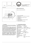
Shifting unit with micrometer screw:
1e
1d 1c
1f
1a
1b
1c
1d
1e
1f
1g
1b
1a
1g
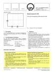
– Fix the shifting unit and the gearbox support into an optics
base (473 421).
– With the magnet strip pointing downwards attach the gearbox
onto the gearbox support.
– Carefully clamp the coupling to the joint head on the fine
adjustment drive.
– Choose the position of the gearbox for gearing down so that
the coupling rods are neither fully extended nor pushed together and so that the angle between the elements of the
universal joint is as small as possible (and never larger than
45°).
swivel head
micrometer screw
horizontal hole
vertical hole
thumb screw
return spring
stem
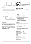
Gearbox for gearing down:
6
Note
Because the gearbox for gearing down with the universal joint
has an "inactive" gear approx. 6 rotations of the gear button are
necessary when the direction of rotation is changed until the
clamped component is shifted.
2a
2b
2c
2a universal joint
2b attachment magnet strip
2c rotary button with lever
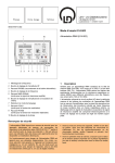
Gearbox support:
3a
3a support plate
3b stem
3b