1
Betriebsanleitung
BOCKWOLDT
Operating Instructions
GETRIEBEMOTORENWERK
BFK458
Spring-loaded brakes with electromagnetic release
3. Accessories
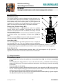
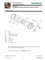
Hand Release ( 8 )
The manual release is used to release the brake by hand (e.g.
at a power failure) and can be retrofitted. It springs back to the
base positon automatically after operation. By pulling at the
hand release lever, the armature plate is pulled against the
magnetic coil, leading to an air gap between rotor and armature
plate. The rotor can be turned easily. The brake is released.
Flange ( 9a ), Friction Sheet ( 9b )
An intermediate flange ( 9a ) can be used if no suitable
counter friction face is available. This flange can be fitted by
screws on two reference circles. In addition, the flange can hold
the dust protection ring.
If a smooth and machined counter surface is available, but suitable
as a friction surface (e.g. aluminium), a friction sheet ( 9b ) is
used.
The friction sheet ( 9b ) of rust-proof steel also protects against
contact corrosion, even at longer machine downtimes.
8
Image 2
7
13
11
9b
9a
10
Cover Ring ( 10 )
h 1 max.
The cover ring protects the brake against the exit or ingress of
dust, humidity, dirt, etc. The ring is pulled over the completely
assembled brake, with the sealing lips being inserted into the respective grooves. In case that
no intermediate flange is used, the counter surface must be equipped with a receiving groove.
Brass Plate ( 13 )
A brass plate can be inserted between armature plate ( 1 ) and magnetic coil ( 5 ) for fast
separation, which leads to reduced incidence times of the brake.
4. Fitting Information
4.1 Installation of Brake
If no suitable friction surface is available, an intermediate flange ( 9a ) or a friction sheet ( 9b )
is used.
Draw hub ( 4 ) onto shaft [ fit feature k6 up to Ø 50, more than Ø 50 m6 ] aufziehen and fix axially by
means of a locking ring. The torque transmission takes place via a fitting key connection according
to DIN 6885.
Push rotor ( 3 ) onto hub ( 4 ).
Insert the fastening screws ( 11 ) through the bore holes in the magnetic coil ( 5 ) and screw them
into the relevant tapped bores of the counter friction surface. Please remove the assembly clips
which protect the sleeve bolts ( 7 ) against torsion during transport.
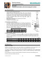
For safety reasons, please now control the air gap sLÜ between armature plate ( 1 ) and magnetic
coil ( 5 ) at three points, by using a feeler gauge.
Operating Instructions
-2-
BOCKWOLDT