1
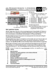
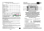
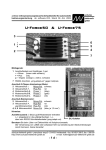
Betriebsanleitung
Typ
Eingangsspannung
Input voltage
Ladezeit
Charging time
Ausgangsspannung
Output voltage
Nennausgangsstrom
Nominal output current
Operating instructions
SSE90
Bitte sorgfältig beachten!
Please observe carefully!
SSE901205
SSE902405
SSE904805
85VAC....270VAC
120VDC....400VDC
85VAC....270VAC
120VDC....400VDC
85VAC....270VAC
120VDC....400VDC
ca. 200s
ca. 200s
ca. 200s
12VDC (11,0V im Pufferbetrieb)
12VDC (11,0V in buffering mode)
Pufferzeit
Hold-up-time
Vorsicherung - träge
Fuse for input - delayed
BxHxT
Maße
dimensions WxHxD
Gewicht
weight
24VDC (22,5V im Pufferbetrieb)
24VDC (22,5V in buffering mode)
48VDC (46,0V im Pufferbetrieb)
48VDC (46,0V in buffering mode)
8,0A
5,0A
2,5A
typ. 1,0A 60s
typ. 1,0A 37s
typ. 1,0A 16s
bei 115VAC 2,5Amp. / bei 230VAC 1,25Amp.
at 115VAC 2,5Amp. / at 230VAC 1,25Amp.
94mm x 99mm x 118mm
ca. 2,20kg
ca. 2,20kg
Allgemeine Sicherheitsvorschriften :
General safety rules :
Beim Umgang mit Produkten, die mit elektrischen Spannungen in Berührung kommen,
müssen die gültigen VDE / IEC / EN Vorschriften beachtet werden. Besonders sei auf folgende
Vorschriften hingewiesen:
VDE 0100, VDE 0550 / 0551, VDE 0711, VDE 0860, IEC 664, IEC 742, IEC 570, IEC 65
Bei Nichtbeachtung der Bedienungsanleitung oder der Anschlußvorschrift, z.B. bei
Vertauschen der Anschlußklemmen, kann das Gerät oder die Anlage beschädigt werden und
der Betreiber verliert seinen möglichen Haftungsanspruch.
Werkzeuge dürfen an Geräten, Bauteilen oder Baugruppen nur benutzt werden, wenn
sichergestellt ist, daß die Geräte von der Versorgungsspannung getrennt
sind und elektrische Ladungen die in im Gerät befindlichen Bauteile gespeichert
sind, vorher entladen wurden.
Vor dem Öffnen des Gerätes den Netzstecker ziehen oder sicherstellen, daß das Gerät
stromlos ist. Bauteile, Baugruppen oder Geräte dürfen nur in Betrieb genommen werden,
wenn sie vorher in ein berührungssicheres Gehäuse eingebaut wurden. Während des
Einbaus müssen sie stromlos sein.
Spannungsführende Kabel oder Leitungen mit denen das Gerät, das Bauteil oder die
Baugruppe verbunden sind müssen stets auf Isolationsfehler oder Bruchstellen untersucht
werden. Bei Feststellen eines Fehlers in der Zuleitung muß das Gerät unverzüglich aus dem
Verkehr genommen werden, bis die defekte Leitung ausgewechselt worden ist.
Der Anwender hat dafür Sorge zu tragen, daß die angegebenen Gerätedaten nicht
überschritten werden.
Wenn aus den vorgelegten Beschreibungen für den Anwender oder Erwerber nicht eindeutig
hervorgeht, welche Kennwerte für ein Gerät oder Bauteil gelten, so muß stets ein Fachmann
um Auskunft ersucht werden.
Im übrigen unterliegt die Einhaltung von Bau- und Sicherheitsvorschriften aller Art ( VDE, TÜV,
Berufsgenossenschaften ) dem Anwender / Käufer.
When working with products which are in contact to dangerous electrical voltages, attention
must be payed to the relevant valid VDE / IEC / EN regulations. Especialy with refrence to the
following rules:
VDE 0100, VDE 0550 / 0551, VDE 0711, VDE 0860, IEC 664, IEC 742, IEC 570, IEC 65
In case of non-observance of this instructions, the unit or other equipment might be damaged
and no warranty or liability could be accepted.
When it is necessary to use tools with the units, components parts or subassemblies make it
sure, that the power is disconnected from the units and all electric charge which is stored in
components inside the unit are discharged.
Before opening the equipment disconnect the power cord or make sure, that the power is off
and the unit is currentless. It is only allowed to set components parts, subassemblies or units
into operation, if they are mounted in a shockproof housing. During the installation the unit
has to be currentless and the power has to be off.
Lifeparts (power cords and leads) which are connected to the units, components or
subassemblies have to be inspected for damage insulation or breaking. If a failure at the
power cord is detected the unit or the subassembly has to be put out of service at once. It is not
allowed to reopen the unit or the subassembly before replacing the damaged power cord.
It is the user’s responsibility to see that the marginal values of the equipment are not exeeded.
If it is not to distinguished for the not industrial ultimate user by the presented operating
instruction, which electrical data are the correct for the unit or the subassembly, a technical
adviser has always to be asked for technical information.
The observance of construction requirements and safety rules (VDE, IEC, employers liability
insurenance i.e.) is subject to the user/customer.
Inductive consumers (contactors, motors, solenoid valves etc.)
which have not been correctly interference-suppressed in
accordance to the relevant guidelines (varistors, RC elements, etc.)
may cause buffering regulation to malfunction.
Induktive Verbraucher (Schütze, Motoren, Magnetventile, etc.) die
nicht ordnungsmäßig nach den relevanten Richtlinien entstört sind
(Varistoren, RC-Glieder, etc.), können zur Störung der
Pufferregelung führen.
ca. 2,20kg
Technische Daten
Technical Data
Sicherheitskleinspannung
Extra low safety potential
Tropentauglich - Gießharzvollverguß
Suitable for the tropics - Epoxy resin casted
Kurzschlußfest, überlast- und leerlaufsicher
Short- circuit proof, no-load and overload safe
Die gelbe LED “Laden” signalisiert das Laden des
Puffermoduls.
Die weiße Bi-Color LED “DC OK / DC Fail” signalisiert bei grün
die Ausgangsspannung ist OK (auch im Pufferbetrieb),
bei rot signalisiert die LED eine zu niedrige
Ausgangsspannung.
Zur besseren Wärmeabfuhr sollten die Geräte einen
Mindestabstand zu anderen Geräten von 15mm halten.
Die Gleichspannungspuffermodule eignen sich zur Montage
auf 35mm Hutprofilschienen. Befestigungsalternativen siehe
Rückseite dieser Bedienungsanleitung.
The yellow LED “Charging” signals the charging of the
buffermodule.
If the white bi-color LED lights green, it means the output voltage
is OK (even when running in buffering mode)
If the white bi-color LED lights red, it means the output voltage is
to low.
Ausgangsgrößen
Regelabweichung Last
< 0,5% bei Laständerung 0...100%
Control deviation load
< 0,5% with load variation 0...100%
To be better cooled, the devices should holds a minimum-distance
of 15mm to other appliances.
The DC-buffer modules are suitable to be fitted on 35mm DIN-rail.
Mounting alternatives are shown on backpage.
Regelabweichung Netz
< 0,5% bei Netzspannungsänderung + 10%
Control deviation supply
< 0,5% with supply variation + 10%
Regelzeit
< 1 mSek. bei Laständerung 10...90%
Control time
< 1 msec. with load variation 10...90%
Eingangsgrößen
Um den Schutz des Schaltnetzteiles vor Überspannung im Eingangskreis zu gewährleisten,
ist eine Vorsicherung vorzusehen
(Wert siehe Tabelle oben).
To protect the input of the power supply
against overvoltage, the input has to be fused
as shown in the table above.
Input data
Eingangswechselspannung
85 - 270VAC
Input voltage AC
Eingangsgleichspannung
85 - 270VAC
120 - 400VDC
Input voltage DC
120 - 400VDC
Ladezeit
ca. 200s
Charging time
approx. 200s
0 - 400Hz
Output data
Pufferspannung
siehe Tabelle links
Buffered voltage
see table left
Strombegrenzung
1,2 x I-Nenn
Current limiting
1,2 x I-nominal
Restwelligkeit
< 50 mVss
Residual ripple
< 50 mVpp
Regelgrößen
Control data
Betriebsdaten
Operating data
Einschaltdauer (ED)
100%
Duty circle
100%
Arbeitstemperatur
- 40°C bis +80°C
Operating temperature
-40°C to +80°C
Leistungsabweichung bei Temp.
ab 50°C
Derating
from 50°C
Lagertemperaturbereich
-40°C...+105°C
Storage temperature range
-40°C...+105°C
Kühlung
natürliche Konvektion
Cooling
selfcooling
empfohlener Freiraum je 15mm
Schutzeinrichtungen
Montage auf Hutschiene / Mounting on rail
z.B. SSE902405
i.e. SSE902405
L1
N
Netz
Line
Gleichstrom
versorgung
gepuffert
recommended respective distances 15mm each
Safety devices
Vorsicherung
siehe Tabelle links
Fuse recomended for input
see table left
Ausgangssicherung
nicht erforderlich da kurzschlussfest
Output fuse
not necessary - cont. short-circuit proof
Überlastschutz
im Gerät integriert
Overload protection
integrated into device
MTBF
>380.000 h
MTBF
> 380.000 h
Netzspannung
line-voltage
85VAC - 270 VAC
oder / or
120VDC - 400VDC
Sicherheitsdaten
N
PE
L1
Laden
Charging
Green / DC
OK
Red / DC
Fail
Klemmenbelegung / Terminal disposition
Safety data
Prüfspannung Trafo
5 kVac gemäß VDE 0551
Test voltage transformer
5 kVac in accordance to VDE 0551
Hochspannungsfestigkeit
Eingang / Ausgang 4,4 kVac
High-voltage resistance
Primary circuit - secondary circuit 4,4 kVac
acc. to VDE 0806 / IEC 380
nach VDE 0806 / IEC 380
DC Power
supply
buffered
0 - 400Hz
Funkenentstörgrad
gemäß VDE 0871 B, EN 55022/B
Degree of EMI suppression
in accordance to VDE 0871 B and EN 55022/B
Schutzkleinspannung
PELV (EN60204), SELV (EN 60950)
Extra low safety potential
PELV (EN60204), SELV (EN 60950)
Schutzklasse
Klasse 1, mit PE Anschluss (EN 60950)
protection class
Class 1, with PE connection (EN 60950)
Umgebungsfeuchte
95% relative Feuchte im Jahresdurchschnitt,
Ambient humidity
95% rel. humidity, yearly average dewing
Betauung möglich - tropentauglich
DC - Output
allowed for use in tropical ambient
DC - Output
Geeignet für
Hutschienenprofil
nach DIN 46277
Suitable for rail
acc. to DIN 46277
Derating
L1
Laden
Charging
Netz
Line
Green / DC OK
Red / DC Fail
N
1,2
Gleichstromversorgung
gepuffert
Ausgangsstrom
Output current
Protective class enclosure
IP 65
Schutzart Klemmen
IP 20 (VGB4)
Protective class terminals
IP 20 (VGB4)
Rüttelfestigkeit
>30g bei 33Hz in X,Y und Z,
Vibration proof
>30g at 33Hz in X, Y and Z,
Angewandte Bauvorschriften
DC Power supply
buffered
DC - Output
Verbraucher
Consumer
+
Dauerbetrieb
1,0
IP 65
nach IEC 68 und DIN 41640
Iout
Inenn
DC - Output
Schutzart Gehäuse
acc. to IEC 68 and DIN 41640
Applied construction regulations
gemäß VDE
VDE 0100, 0110, 0113, 0551, 0160/W2, 0806
according to VDE
VDE 0100, 0110, 0113, 0551, 0160/W2, 0806
IEC
IEC 60950,IEC61000-6-1-2-3-4,IEC60068-2-3
IEC
IEC 60950,IEC61000-6-1-2-3-4,IEC60068-2-3
IEC 60068-2-11-52,IEC 60529,IEC 380
EN
-
0,8
EN60950,EN61000-1-1,EN61000-1-2,
IEC 60068-2-11-52,IEC 60529,IEC 380
EN
EN61000-6-3,EN61000-6-3,EN50178,EN55022
EN55011,EN61000-3-2,EN61000-3-3,EN50204
EN55011,EN61000-3-2,EN61000-3-3,EN50204
EN60204,EN60529,EN61000-4-2-3-4-5-6-8-11
EN60204,EN60529,EN61000-4-2-3-4-5-6-8-11
EN60068-1,EN60068-2-1-2-3-6-27-30
EN60068-1,EN60068-2-1-2-3-6-27-30
EN45501,EN50021,EN61558-2-17
0,6
CSA / UL
0,4
CSA-C 22.2 / UL60950, UL508, UL1950
Mechanik
0,2
Befestigung
0
0
10
20 30 40 50 60 70 80 90 100
Temperatur in Celsius
T / C°
EN60950,EN61000-1-1,EN61000-1-2,
EN61000-6-3,EN61000-6-3,EN50178,EN55022
EN45501,EN50021,EN61558-2-17
CSA / UL
CSA-C 22.2 / UL60950, UL508, UL1950
Mechanics
Auf Schiene nach DIN 46277
Mounting
on rails acc. to DIN 46277
Stand / Updated: 12.April 2011
Postfach 1521
D - 22905 Ahrensburg
Phone: +49 4102 42082
Fax: +49 4102 40930
E-Mail: [email protected]
Internet: www.feas.com
3.
2.
Nut M3
Screw M3
Postfach 1521
D - 22905 Ahrensburg
Mutter M3
Schraube M3
Phone: +49 4102 42082
Fax: +49 4102 40930
Schraube M3x6
Screw M3x6
Mutter M3
Nut M3
Suitable for
M6 screws
Geeignet für M6
Schrauben
6,1 mm
Hutschiene
rail
1.
Befestigung Alternativen.
Mounting alternatives
E-Mail: [email protected]
Internet: www.feas.com