1
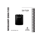
Agilent U1586B Temperature Adapter
Operating Instructions
The U1586B temperature adapter is designed for Agilent handheld digital multimeter (DMM), Agilent handheld
oscilloscope, and K-Type thermocouple.
OUTPUT: mV output proportional
to inside battery. °C and °F as the
position of slider switch
Slider switch:
• OFF: inside battery level
• °C: 1 mV/°C
• °F: 1 mV/°F
Conform to European Union Directives IEC/ EN
61010-12001 (2nd Edition)
INPUT: K-type thermocouple with
miniature connector
Assistance
For technical assistance, contact your nearest Agilent Sales Office or visit the Agilent website at
www.agilent.com/find/assist for further information.
Safety Informations
Please use the Agilent U1586B temperature adapter only as specified in this manual. Otherwise, the protection
provided may be impaired. Refer to the safety information below.
WARNING
To avoid possible electric shock, personal injury or damage to this instrument and ensure that you use the adapter
safely, follow these guidelines:
- Do not use the adapter if it is damaged. Before you use the adapter inspect the case. Look for cracks or missing
plastic. Pay particular attention to the insulation surrounding the connectors.
- Do not touch thermocouple probe to hazardous voltage.
- Do not operate the adapter around explosive gas, vapor or dust.
- When servicing the adapter, use only specified replacement parts.
- Removed all connections as battery replacement
- Use caution when working above 30 V ac rms, 42 V peak or 60 V dc. Such voltage pose a shock hazard.
- Avoid working alone.
- Do not operate the adapter as the cover removed or loosened.
CAUTION
To avoid possible damage to the temperature adapter or to the equipment under test, follow below guidelines:
- Do not connect output banana plugs to any power source.
- Use the proper terminals, function, and range for your measurements.
AC - Alternating Current
Caution, risk of danger (Refer to the user’s
and service guide for details)
Double Insulation
DC - Direct Current
Ground
Battery Voltage Test
Set the adapter’s slider switch to OFF position, the output will output the proportional mili-volt to represent the
battery voltage inside. The proportional scale is DC 9.9 mV per 1 V of battery voltage inside. The operating voltage
suggested is up to 7.5 V of battery. So, always make sure the mili-volt output is up to 74.2 mV before temperature
measurement.
Battery Voltage
Output of U1586B
10 V
9V
8V
7.5 V
99.0 mV
89.1 mV
79.2 mV
74.2 mV
Introductions
The U1586B temperature adapter accepts any K-Type thermocouple with miniature connector and converts it to 1
milli-volt per degree (Celsius or Fahrenheit).
Standard Item Purchased Checklist
The following items are included when you make a purchase:
•
U1586B temperature adapter
•
U1184A K-Type bead probe
•
Operation Instructions sheet (this sheet)
General Specifications
Specifications
Temperature Adapter
Operating Temperature
0 °C to 55 °C (14 °F to 131 °F)
Storage Temperature
–20 °C to 70 °C (–4 °F to 158 °F)
Relative Humidity
Max 80% RH for temperature up to 35 °C decreasing linearly to 50% RH at 55 °C
Battery life
1600 hours approximately based on alkaline battery
Altitude
2000 meters
EMC Compliance
Susceptibility and Emissions: Commercial Limits per EN61326-1
Dimensions (HxWxD)
31 mm (H) x 59 mm (W) x 113.5 mm (L)
Weight
120 grams
Power Supply:
Single standard 9 V Battery can use Alkaline or Carbon-zinc.
Battery Types
ANSI/NEDA
IEC
Alkaline
1604A
6LR61
Carbon-zinc
1604D
6F22
Electrical Specifications
Range
Resolution
–50 °C ~ 1000 ° C
1 mV/°C
–58 °F ~ 1832 °F
1 mV/°F
Accuracy
± (% of reading + no. of least significant digits) at 23 °C ± 5 °C, with relative
humidity less than 80% R.H.
–50 ~ –21 °C
2.5% + 2 °C
–20 ~ 350 °C
0.5% + 2 °C
351 ~ 500 °C
1.75% + 2 °C
501 ~ 1000 °C
2% + 2 °C
–58 ~ –5.8 °F
2.5% + 3.6 °F
–4 ~ 662 °F
0.5% + 3.6 °F
664 ~ 932 °F
1.75% + 3.5 °F
933 ~ 1832 °F
2% + 3.6 °F
• The accuracy specifications does not include the error of the probe or the digital multimeter, and this
adapter should be stabilized for at least one hour on the DUT to be measured. Please refer to the probe
accuracy specifications for additional details.
• Accuracy enhancement for 351 °C ~ 500 °C, subtract 3 degrees from the reading. The accuracy is now
0.75% ±2 °C.
• Accuracy enhancement for 663 °F ~ 932 °F, subtract 5.4 degrees from the reading. The accuracy is now
0.75% ±3.6 °F.
Operation
Follow the procedures provided to select Celsius or Fahrenheit temperature unit in proportion to mili-volt output
using slider switch:
1. Ensure the temperature adapter is stabilized in operating environment.
2. Switch the adapter slider’s switch to set °C or °F.
3. Plug the banana plugs into V/COM terminals on multimeter.
4. Set the DC voltage measurement and adequate range on multimeter or oscilloscope in use.
5. Plug the miniature K-Type thermocouple probe into adapter.
6. Observe the DC mili-volt on a multimeter which is proportional to the temperature. (1 mV is 1 °C or ° F)
7.
Select a better resolution to 0.1 mV on a multimeter if want to see the difference to 0.1 degree.
Calibration Equipment
The pre-calibration guide lines are shown as follows:
•
Be sure you are a qualified person to perform the calibration
•
The environment should be 23 °C ±2 °C and the relative humidity (RH) shall be < 80%.
The test equipment requirements listed in table below or equivalents are required to perform the calibration and
performance verification test procedures. Alternative equipment may be used as long as the accuracy is as good
as or better than the specifications listed.
Operating Range
Accuracy
Required
K-Type Thermocouple
Simulator or Calibrator
–50 ~ 1000 °C
–58 ~ 1832 °F
≤ ±0.1% + 1 °C
CL-300-1000C from OMEGA or Fluke-5520A
Multimeter
DC 1000.0 mV
≤ ±0.1%
Agilent-U1251A, U1252A or Agilent-34405A
–5 ~ 38 °C
≤ ±0.1% + 0.5 °C
Standard Source
Ice Point Reference
Chamber
Recommended
Equipment
TRCIII from OMEGA or Fluke -5520A
Adjustment Procedures
The following procedures are to be performed in sequence after another to ensure a correct calibration sequence.
Celsius Temperature Offset Adjustment
1.
2.
3.
4.
5.
Set the operating range of the digital multimeter to DC 1000.0 mV.
Set the reference standard to 0 ºC.
Switch the adapter’s slider to the ºC position.
Connect the K-type miniature connector from the reference standard into the input of U1586B adapter.
Plug in the banana ends of the adapter’s output to the V and COM input terminals of the digital
multimeter.
6. Wait for at least 30 seconds for the signal conversion from ºC to Volts to stabilize at the multimeter
display.
7. Observe that the multimeter reading should display a voltage of 0.0 mV ± 0.2 mV.
8. If the multimeter reading display does not meet the required voltage, unscrew 2 Phillips head screws
at the back panel of the adapter using a Phillips tip screwdriver and remove the rear cover.
9. Look for VR3 (refer to Figure 1 for the location of VR3 in the adjustment diagram) and carefully adjust
the variable resistor using a small Phillips tip screwdriver until the display of the multimeter meets
the required reading of 0.0 mV ± 0.2 mV.
10. After performing the adjustment of VR3, remember to replace the rear cover of the adapter or proceed
to the next calibration process.
Celsius Temperature Gain Adjustment
1.
2.
3.
4.
5.
Set the operating range of the digital multimeter to DC 1000.0 mV.
Set the reference standard to 300 ºC.
Switch the adapter’s slider to the ºC position.
Connect the K-type miniature connector from the reference standard into the input of U1586B adapter.
Plug in the banana ends of the adapter’s output to the V and COM input terminals of the digital
multimeter.
6. Wait for at least 30 seconds for the signal conversion from ºC to Volts to stabilize at the multimeter
display.
7. Observe that the multimeter reading should display a voltage of 300.0 mV ± 0.2 mV.
8. If the multimeter reading display does not meet the required voltage, unscrew 2 Phillips head screws
at the back panel of the adapter using a Phillips tip screwdriver and remove the rear cover.
9. Look for VR1 (refer to Figure 1 for the location of VR1 in the adjustment diagram) and carefully adjust
the variable resistor using a small Phillips tip screwdriver until the display of the multimeter meets
the required reading of 300.0 mV ± 0.2 mV.
10. After performing the adjustment of VR1, remember to replace the rear cover of the adapter or proceed
to the next calibration process.
Fahrenheit Temperature Offset Adjustment
1.
2.
3.
4.
5.
6.
7.
8.
Set the operating range of the digital multimeter to DC 1000.0 mV.
Set the reference standard to 32 ºF.
Switch the adapter’s slider to the ºF position.
Connect the K-type miniature connector from the reference standard into the input of U1586B adapter.
Plug in the banana ends of the adapter’s output to the V and COM input terminals of the digital
multimeter.
Wait for at least 30 seconds for the signal conversion from ºC to Volts to stabilize at the multimeter
display.
Observe that the multimeter reading should display a voltage of 32.0 mV ± 0.2 mV.
If the multimeter reading display does not meet the required voltage, unscrew 2 Phillips head screws
at the back panel of the adapter using a Phillips tip screwdriver and remove the rear cover.
9. Look for VR4 (refer to Figure 1 for the location of VR4 in the adjustment diagram) and carefully adjust
the variable resistor using a small Phillips tip screwdriver until the display of the multimeter meets
the required reading of 32.0 mV ± 0.2 mV.
10. After performing the adjustment of VR4, remember to replace the rear cover of the adapter or proceed
to the next calibration process.
VR3: To adjust °C
offset values
VR4: To adjust °F
offset values
Miniature
connector for
Temperature
source
VR2: To adjust °F
gain values
VR1: To adjust °C
gain values
Banana Ends to be
plugged into a
multi-meter
Figure 1: U1586B Adjustment Diagram
Always remember to adjust the gain of the temperature in Celsius before Fahrenheit.
Fahrenheit Temperature Gain Adjustment
1.
2.
3.
4.
5.
6.
Set the operating range of the digital multimeter to DC 1000.0 mV.
Set the reference standard to 572 ºF (300 ◦C).
Switch the adapter’s slider to the ºF position.
Connect the K-type miniature connector from the reference standard into the input of U1586B adapter.
Plug in the banana ends of the adapter’s output to the V and COM input terminals of the multimeter.
Wait for at least 30 seconds for the signal conversion from ºF to Volts to stabilize at the multimeter
display.
7. Observe that the multimeter reading should display a voltage of 572.0 mV ± 0.2 mV.
8. If the multimeter reading display does not meet the required voltage, unscrew 2 Phillips head screws
at the back panel of the adapter using a Phillips tip screwdriver and remove the rear cover.
9. Look for VR2 (refer to Figure 1 for the location of VR2 in the circuit diagram) and carefully adjust the
variable resistor using a small Phillips tip screwdriver until the display of the multimeter meets the
required reading of 572.0 mV ± 0.2 mV.
10. After performing the adjustment of VR2, remember to replace the rear cover of the adapter.
Maintenance
Repair or service not cover this manual should be performed only by qualified personnel.
To avoid electrical shock or damage to the adapter, do not get water inside the case .
Cleaning
• Periodically wipe the case with a damp cloth and mild detergent. Do not use abrasive or solvents.
Troubleshooting
Battery Replacement
If the temperature adapter does not perform properly, follow the steps below to identify the problem:
1. Before inspecting the battery voltage, switch the adapter’s slider to OFF position. Replace the battery if
the voltage output ends less than 74.2 mV.
2. Check the K-type thermocouple probe whether has been plugged into adapter or any crack on bead end.
Replace with new one as necessary.
3. Verify that the DC voltage and range on the multimeter is correct.
Never discharge the battery by short battery or reverse polarity in any subjects.
The adapter is powered by 9 V battery. Ensure to use specified battery only.
Following is the procedures for battery replacement:
1. Removed all the connections for thermocouple probe and banana plugs.
2. Loose two screw on the bottom case and remove the bottom case.
3. Replace the specified batteries and ensure the polarity of the batteries.
4. The red and black surrounding plastic cases are for “+” and “–” banana plug ends. Please ensure the
polarity and color.
5. Once done place back the bottom case to its original place and tighten the screw.
© Agilent Technologies, Inc. 2009-2010
First Edition, March 30, 2010
Printed in Malaysia
U1586-90101