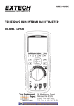
Download User Manual of 898
Transcript
A Process mA Loop Calibrator/ MultiMeter Main Fields of Application: Process industries, Metallurgy, Power generation, Research, Laboratories, Maintenance, After sales service, Education and so on. User Programmable Functions Copyright© 2004 Larry Tsai. All rights reserved. INSTRUCTION MANUAL REVISION HISTORY Version 1.0 1.1 1.2 Change Summary Created 1. Replace the figure-44 2. Change page 82 for battery charge 3. Change page 86 for adaptor 4. Specify thermal condition for DC Current accuracy 1. Change loop power on page 70, 76, 85 2. Change optional accessories on page 86 Date 2004/10/08 2005/02/25 Author LT LT 2005/12/23 LT Copyright Statement Copyright© 2004 Larry Tsai. All rights reserved. No part of this publication may be reproduced in any form or by any manner or used to make any derivative such as translation, transformation, or adaptation without our authorization and permission. All the Trademarks belong to their respective proprietors. User Programmable Functions II Contents SAFETY INFORMATION .........................................................................................1 QUICK START............................................................................................................3 OUTPUT- SETUP AND OUTPUT A PROCESS CALIBRATION SIGNAL ..................3 INPUT- ACV AND FREQUENCY MEASUREMENTS ...........................................4 INTRODUCTION........................................................................................................5 GETTING START WITH YOUR METER..............................................................7 DISPLAY ILLUSTRATION ..................................................................................7 ROTARY SWITCH.............................................................................................8 INPUT AND OUTPUT TERMINALS ............................................................9 PUSH-BUTTON OPERATIONS .............................................................................10 INPUT OPERATIONS ................................................................................10 OUTPUT OPERATIONS ............................................................................13 POWER-ON OPTIONS ............................................................................................15 HOW TO ENTER SETUP MODE .........................................................................15 FACTORY DEFAULT.......................................................................................16 BAUD RATE ..................................................................................................17 PARITY CHECK..............................................................................................18 DATA BIT ......................................................................................................18 ECHO ............................................................................................................19 PRINT ONLY ..................................................................................................19 PERCENTAGE (%) SCALE FOR 4-20MA OR 0-20MA MEASURING....................20 MINIMUM FREQUENCY MEASURING ..............................................................20 BEEP FREQUENCY .........................................................................................21 TEMPERATURE UNIT .....................................................................................22 DATA HOLD/REFRESH HOLD ........................................................................23 AUTO POWER OFF.........................................................................................24 BACKLIT DISPLAY.........................................................................................25 DUAL DISPLAY .............................................................................................26 SIMPLE AND EFFICIENT MA LOOP CALIBRATOR......................................27 SET COARSE OR FINE ADJUSTMENT...................................................27 STEP OUTPUT............................................................................................28 FAST SPAN CHECK ..................................................................................28 SCAN OUTPUT ..........................................................................................29 RAMP OUTPUT..........................................................................................32 SELF-PROTECTION ...............................................................................................35 OUTPUT/ STANDBY .................................................................................35 III LOW BATTERY/ BATTERY CAPACITY ................................................35 OVERLAOD ALERT FOR VOLTAGE MEASUREMENT.......................36 CALCULATION FUNCTION .................................................................................37 DYNAMIC RECORDING ..........................................................................37 DATA HOLD (MANUAL TRIGGER) .............................................................39 REFRESH HOLD (AUTO TRIGGER) ............................................................39 RELATIVE (ZERO) ....................................................................................40 1 MS PEAK HOLD ..........................................................................................41 REMOTE COMMUNICATION ..............................................................................43 MULTI-DISPLAY MULTIMETER ........................................................................45 SELECTION BY HZ BUTTON ...........................................................................45 SELECTION BY DUAL BUTTON .....................................................................47 TEMPERATURE MEASUREMENT ....................................................................49 OPERATE IN PROCESS FIELD ............................................................................51 LINE POWER VOLTAGE MEASUREMENT...........................................51 LOOP POWER MEASUREMENT .............................................................52 PRESSURE TRANSDUCER MEASURING ...........................................................53 LOOP CURRENT MEASUREMENT ...................................................................54 SOURCE MODE OF MA OUTPUT .....................................................................55 SIMULATING MODE OF MA OUTPUT .............................................................56 SIMULATION OF A TWO-WIRE TRANSMITTER ON A CURRENT LOOP ..............58 LOOP 24V FOR TWO-WIRE TRANSMITTER ....................................................59 RESISTANCE/ CONTINUITY MEASUREMENT....................................60 DIODE CHECK...........................................................................................62 BIPOLAR JUNCTION TRANSISTOR.......................................................63 JFET SWITCH TEST ..................................................................................65 CALIBRATING THE METER................................................................................67 INTRODUCTION .......................................................................................67 ENVIRONMENTAL CONDITION ............................................................67 WARM UP...................................................................................................67 RECOMMENDED TEST EQUIPMENT ....................................................68 GENERAL SPECIFICATION .................................................................................69 INPUT SPECIFICATIONS ......................................................................................71 OUTPUT SPECIFICATIONS ..................................................................................75 MAINTENANCE .......................................................................................................76 SERVICE.....................................................................................................76 HOW TO CHARGE BATTERY..................................................................77 IV BATTERY REPLACEMENT .....................................................................82 FUSE REPLACEMENT ..............................................................................83 CLEANING .................................................................................................84 STANDARD ACCESSORIES ....................................................................85 OPTIONAL ACCESSORIES ......................................................................86 V SAFETY INFORMATION This instrument is a hand-held, battery-operated instrument for testing and troubleshooting power electronic systems. If this device is damaged or something is missing, contact the purchasing place immediately. A WARNING identifies conditions and actions that may cause hazard(s) to the user; a CAUTION identifies conditions and actions that may damage this Device. Following Table-1 explain international electrical symbols used on this meter. Table- 1. International Electrical Symbols AC - Alternating Current DC - Direct Current AC and DC - Alternating and Direct Current Ground Double Insulation See Explanation In The Manual 1 SAFETY INFORMATION Warnings and Cautions To avoid electric shock, injury, or damage to this instrument and ensure that you use the meter safely, follow the safety guidelines lised below: • Read this operation manual completely before using this device and follow all safety instructions. • This device is for indoor use, altitude up to 2,000 m. • Avoid working alone. • Use the device only as specified in this manual; otherwise, the protection provided by the meter may be impaired. • Never measure Voltage when the current measurement is selected. • Do not use this device if it looks damaged. • Inspect the leads for damaged insulation or exposed metal. Replace damaged leads. • Disconnect the power and discharge all high-voltage capacitors before testing in the resistance, continuity, and diode function. • Be cautions when working above 70V DC or 33VRMS and 46.7V peak, such voltages may cause a shock hazard. • Always keep your hands behind the protective guard of the probe as measuring. • Select the proper function and disconnect the test leads from test points before changing functions. • Always use specified rechargeable battery for charging. • The meter is safety-certified in compliance with EN61010 (IEC 1010-1, IEC 1010-2-031) Installation Category ΙV 600V/ III 1000V Pollution Degree 2. In order to maintain its insulation properties, please be sure to use with the standard or compatible test probes. • CE requirement: Under the influence of R.F field according to standard, the supplied test leads will pick up induced noise. To have better shielding effect, a short-twisted lead should be used. 2 QUICK START WARNING Read "SAFETY INFORMATION" before using this device. OUTPUT- Setup and output a process calibration signal 1. Turn the function switch to mA simulate 2. Connect the terminals by alligator-clip leads to the device to be simulated which the loop has 24V. Press the OUTPUT button. The process signal will become active. Press 3% to decrease one step, press % 4to increase one step. Fast SPAN check, press and hold “% 4100” for more than 1 second to 100% step. Press and hold “03%” for more than 1 second to 0% step. Press the OUTPUT button again to turn off the signal. 3. 4. 5. 6. 5. 100% SPAN Check: Press and Hold “% 4100” for more than 1second 4. Press 3% to decrease one step, press % 4to increase one step. 3/6. Press OUTPUT button to toggle signal ON/OFF 5. 0% SPAN Check: Press and Hold “03%” for more than 1second. 2. mA Simulate Terminals 2. Turn the function switch to mA Simulate Figure- 1. Quick Output Operation 3 INPUT- ACV and Frequency measurements 1. 2. 3. 4. Turn the function switch to V function " and "COM" input Connect the Red and black test leads to "VΩ terminals.. Touch the probes to the test points and read the display Read the measuring value on display. Primary display shows AC voltage, and secondary display shows frequency. Frequency display ACV display 1. Turn the rotary switch to the V function 2. Connect the INPUT terminals by test leads to the source to be tested Figure- 2. Dual display for ACV/ Hz Measurement 4 INTRODUCTION This device can be used not only for instrument system maintenance, but also for maintaining, servicing industrial meters, testing electronic circuits and electronic equipments. Even the sensor or transmitter in automotive or automatic control system can be measured and calibrated by this meter. Provide you mA Source/ Simulate, Loop 24V with loop current display, external power supply and multi-display multimeter. Make you job simply and efficiently. Main Features: z z z z z z z z z z z z z z z z z z z 24V Loop power supply with loop current monitor 1,200Ω drive capability for 20mA source/ simulation. The % scale readout for 4-20mA or 0-20mA measurement and output Intelligent Output and Standby control Built-in rechargeable battery Smart Charger design without battery removed Brightness EL backlight You are the master to Coarse or Fine turn for outputs Adjustable steps and time interval for Auto Scan Adjustable resolutions and span for linear Ramp output. 1ms Peak hold to catch inrush voltage and current easily Temperature test with the optional of 0°C compensation Frequency, Duty cycle and Pulse width measurements. Dynamic Recording for Min/Max/Average Data Hold with Manual or Auto Trigger and Relative modes Diode and Audible Continuity Test Bi-directional optic computer interface with SCPI commands Safe, precision and speed closed case calibration 50,000 count precision True-RMS digital multi-meter and designed to meet IEC-1010 CAT. IV 600V/ CAT. III 1000V standard 5 Fast Step/ Span Check You can define how many percentages to be increasing or decreasing by 5% and %6. Bi-directional optic computer interface for safe, precision and speed closed case calibration You are the master to Coarse or Fine turn for mA output. To use SET button to select which digit to be adjusted and use 5mA and mA6 buttons to adjust the value. Intelligent Output and Standby control for over current protection For mA simulate/Source, press 5% to increase 25%, Press and hold this button for more than one second to set 100% span. For mA simulate/Source, press %6 to decrease 25%, Press and hold this button Loop24V provides 24V output and indicates the loop current. for more than one second to set 0% span. 1,200 ohms drive capability, 0-20 mA and 4-20 mA for mA source/simulate Auto SACN: Dual slopes, adjustable step and time interval Auto RAMP: adjustable resolution and span for dual slope linear Ramp output. 50,000 count precision True-RMS digital multi-meter and designed to meet IEC 1010 CAT.IV 600V/ CAT. III 1000 Volt Patent Pending in Taiwan, China, USA Built-in Ni-MH rechargeable battery and Smart Charger design without battery removed Figure- 3. Make your job Simply and Efficiently 6 GETTING START WITH YOUR METER Display Illustration Constant Current Output Secondary Display for OUTPUT and INPUT : Output Enable : Output Disable Constant Voltage Output Thermal type for temperature test Square Wave Output for Hz, % mS and Level Remote control SCAN Output Output/ Input units RAMP Output Dynamic Recording SHIFT button operations Alternating/ Direct Current Diode/Audible continuity % 0-20: 0-20mA % 4-20:4-20 mA Auto Range Without ambient temperature compensation Relative Mode Input units Low Battery Auto power off sign Data Hold (Manual Trigger) Primary Display for INPUT Figure- 4. LCD Display 7 Positive or Negative trigger slope for % and ms tests Rotary Switch To turn this device ON and select a function you want by turning the rotary switch (Figure-5). The White sign is for measuring function, and yellow sign is for output function of “mA loop calibrator”. FUNC. Initial 1 2 AC Voltage 3 DC Voltage 4 DC mV 5 6 7 8 9 10 SHIFT by BLUE key OFF Power Off AC mV measurement (Temperature: Ambient compensation) (Temperature: 0°C compensation) Resistance DC mA mA Source Loop 24V mA Simulate Battery charge Audible Continuity / Diode AC mA/ DC mA % scale 4 Start Charge battery 5 6 7 3 8 2 9 10 1 Figure- 5. Rotary Switch 8 INPUT and OUTPUT TERMINALS WARNING To avoid damaging this device, do not exceed the input limit. This device has four terminals which are protected against overloads to the limits shown in the specifications. See the below table: Table- 2. Terminals limit specification. ROTARY SWITCH FUNCTION AC Voltage DC Voltage AC/DC mV (Temperature) Ohm (Ω) Diode ( ) AC/DC Current TERMINALS 1 (V Ω ) 4 (mA) 2 (COM) 2 (COM) “mA Source” OVERLOAD PROTECTION 1000V R.M.S. 1000V R.M.S. for <0.3A short circuit 0.44A/1000V, Quick acting fuse 25mA MAX. 3 4 25mA MAX. “Loop 24V” 3 4 “mA Simulate” 48V MAX. 3 2 48V MAX. Battery Charge 3 2 3 2 4 1 Figure- 6. Terminals 9 PUSH-BUTTON OPERATIONS The operation of push-button is shown as below. When push the button, a related symbol will be lit, and the beeper will sound. Turning the rotary switch to another position will reset current operation of push buttons. INPUT OPERATIONS HOLD: Freeze existing measuring value. Press again to trigger next measuring value Press and hold for more than 1sec. to exit trigger hold. REL: Set the value on the display to be subtracted. TEMP: Press and hold for more than 1 sec. to toggle mV and temperature tests. BLUE: To select DC, AC measuring PEAK: Press and hold for more than 1 sec. to toggle PEAK Hold ON/OFF for V/mA : Press to see battery capacity as input function selected. Press and hold for more than 1 sec. to toggle backlit ON/OFF RANGE: Change measuring range. AUTO: Press and hold for more than 1 sec. to set Auto-range DUAL: Select different combination displays MAX MIN: Press and hold for more than 1 sec to toggle Dynamic recording mode. Press this button momentarily to cycle through MAX, MIN, AVG and present (MAX AVG MIN) readings at recording mode. Figure- 7. Input Buttons. 10 Hz: Select Hz, % and Pulse width tests on Primary display. Press and hold for more than 1 sec. to quit. 1. AC • DC / PEAK (Blue): Select DC, AC, Peak Test z Push this button momentarily to cycle through DC, % scale of mA and AC tests for Current measurement. z Press this button for more than 1 second to toggle 1 ms peak hold ON/OFF at Voltage or Current measurement. The display will show "DH MAX" to indicate PEAK + and show "DH MIN" to indicate the PEAK -. z For Ohm test, push this button momentarily to step through " ", diode and Ohm test. z For Duty cycle and Pulse width tests, press this button for more than 1 second to change the trigger slope or . z For mV measurement, press this button to toggle AC and DC test. z For temperature measurement, press this button to toggle the compensation for environment and 0°C. 2. HOLD: DATA HOLD or Refresh Data Hold z Press this button momentarily to hold the existing displayed digital value and enter trigger mode. z Press this button momentarily again to trigger another data hold z Press this button for more than one second to exit trigger mode. z To select Refresh Hold by set-up mode. The reading can be updated to the indicator automatically when the reading is changed. Simultaneously, the beeper sounds a tone to remind user. 3. HOLD (MAX • MIN): Dynamic Recording z Record maximum, minimum, and calculates true average. z Press this button for more than 1 second to toggle recording mode on or off. z Press this button momentarily to cycle through MAX, MIN, AVG and present (MAX AVG MIN) readings. The meter sounds a tone when a new maximum or minimum value is recorded. z Press this button momentarily to cycle through Peak +, Peak - reading after setting peak mode. The screen shows "DH MAX" to indicate the PEAK + and show "DH MIN" to indicate the PEAK -. 4. ∆ REL (ZERO): Relative function z The relative function shows the difference between the measured value and the stored value. z Press to toggle Relative (∆) ON or OFF. 5. RANGE: z In auto-range, press this button to select manual range and turn off the "AUTO" sign. z In manual range, press this button momentarily to step up 1 range at one time, press this button for more than 1 second to select auto-range. 11 z In auto-range, the "AUTO" is lit and the meter will select an appropriate range for resolution if a reading is greater than maximum available range, "OL"(overload) will be displayed on the display. The meter will select a lower range when reading is less than about 9.5% of full scale. z Push this button momentarily to change measuring range and re-start the PEAK+ and PEAK- measurements after setting the peak mode. 6. DUAL: Dual Display Combination z Press this button momentarily to select different combinations of dual display. Please refer to the chapter of “Multi-display Multimeter”. z Push this button momentarily to re-start a new peak value measurement after setting peak mode. 7. Hz: Select Frequency, Duty Cycle and Pulse Width Tests z For Voltage or Current test, press this button momentarily to enter Frequency test, and Voltage or Current will be indicated on secondary display. Press this button again to step through Frequency, Duty cycle, Pulse width test. Press this button for more than one second to back voltage or current measurement. z Please refer to the chapter of “Multi-display Multimeter” for the combinations of dual display. 8. : Battery check/ Back-lit z Press this button momentarily to see the existing battery capacity. z Press this button for more than 1 second to toggle backlit ON or OFF. Backlit turns off automatically after settling time. 12 OUTPUT OPERATIONS STEP Change: Press 3% to decrease one step, press % 4to increase one step. Fast SPAN Check: Press and Hold “03%” for more than 1 second to 0% step. Press and Hold “% 4100” for more than 1 second to 100% step. SET: Select which Digits to be adjusted The selected position will be flashed on the secondary display. 5 (UP)/ 6(DOWN) mA: Adjust digit, press momentarily to increase/ decrease 1 count for present digit. OUTPUT: Press momentarily to toggle the output state ON and OFF. means this signal has The been sent out, and means the signal has been disabled output. SCAN: Select output modes for Auto SCAN and Auto linear RAMP Output. : Press and hold for more than 1 sec. to toggle backlit ON/OFF Figure- 8. Output Buttons. 13 1. (SCAN): SCAN/ Backlit z Press this button momentarily to cycle through SCAN, RAMP and Normal output modes. z Press this button for more than 1 second to toggle backlit ON or OFF. Backlit turns off automatically after specified period. 2. SET: Select which Digit to be adjusted z For Normal mode, press this button momentarily to move the adjustment position from digit 1, 2, 3, 4, 5 then scroll up to digit 1. For selected position will be flashed on the screen. Digit 1← Digit 5 ← Digit 4 ← Digit 3 ← Digit 2 ← Digit 1 z For SCAN and RAMP mode, press and hold this button for more than 1 second to enter Memory generation adjustment mode. Please refer to the chapter about Memory Generation for detail description. 3. %4100: Increase 25% (This percentage can be set in the memory) z Press this button momentarily to increase 25% is proportional to 0~20mA or 4~20mA. The top scale will be 125%. Press and hold this button for more than one second to set 100% span. 4. 03%: Decrease 25% (The percentage can be set in the memory) z Press this button momentarily to decrease 25% is proportional to 0~20mA or 4~20mA. The bottom scale is 0%. Press and hold this button for more than one second to set 0% span. 5. 5mA: Increase one count. z Press this button momentarily to increase 1 count for present digit. Press and hold this button will repeat above action. 6. mA6: Decrease one count z Press this button momentarily to decrease 1 count for present digit or toggle the polarity of output state. Press and hold this button will repeat above action. 7. OUTPUT: Control the output state z Press this button momentarily to toggle the output state ON and OFF. The means this signal has been sent out. The screen displays for output off. z For the memory adjustment of SCAN and RAMP functions, press this button momentarily to save your setting after finished the setting. 14 POWER-ON OPTIONS How to enter setup mode To press and hold SET button while turn the rotary switch to any ON position. The meter will enter setup mode, these parameters will be remained in non-versatile memory even the meter is turned off. User can configure related parameters on setup mode by following procedures: 1. 2. 3. 4. Press “03%” or “%4100” button to select which menu item to be set. Press “5mA” or “mA6 ” button to change the parameter. Press “OUTPUT” button to save your change. Push “SCAN” button momentarily to exit setup mode. Figure- 9. Power-ON Options 15 Factory Default Following Table-3 describes the outline of the setup menu item and indicates the factory settings. Table- 3. Descriptions for Outline of Setup Menu Item Menu item Factory Setting Selectable Parameters Baud Rate 9600 2400, 4800, 9600, 19200 Data bit Parity ECHO Printer-Onl y Refresh Hold Percent scale for mA 8 None OFF 7 or 8 bits (The stop bit is always 1 bit) None, odd or even ON or OFF OFF ON or OFF OFF OFF means Data hold, 100~1000 variation counts for refresh hold 4-20mA Freq 0.5Hz Beep 4800 Temperatur e *N4 0-20mA, 4-20mA Set minimum measuring frequency, 0.5, 1 or 2 Hz. Set OFF, 4800, 2400, 1200 or 600 Hz for driving frequency. Four combinations can be set: 1. °C only °C/°F 2. °C and °F 3. °F only 4. °F and °C Auto power off 10 Backlit 15 Dual On 0~99 minutes, “0” means to disable auto power off. 0~99 seconds, “0” means to disable to turns off backlit automatically. Enable dual display as initial voltage/Hz or Current/ Hz measurement. Notes: 1. The temperature menu item will be selected once the “ ” sign is lit on the display. Push “SCAN” button for more than one second to enable temperature option, the “ ” will be lit on the display. 16 Baud Rate The baud rate is selected for remote control. It can be set to 2400, 4800, 9600 or 19200 Hz. To select your request as follows: Figure- 10. Baud rate setup for remote control 17 Parity Check The parity check is selected for remote control. It can be set to none, even or odd bit. To select the parity as follows: Figure- 11. Parity Check setup for remote control Data Bit The data bit is selected for remote control. It can be set to 8 or 7 bits. The stop bit is defined to 1 bit and can’t be changed. To select the data bit as follows: Figure- 12. Data bit setup for remote control 18 Echo With ECHO ON, the meter echoes (returns) all the characters whatever it receives. To enable the Echo as follows: Figure- 13. ECHO Setup. Print only If the remote interface of the meter is under Print-only mode, the meter will print out the measured data when the measuring cycle is completed. The meter sends the newest data to a host automatically and continuously. The meter doesn’t accept any commands from the host under Print-Only enabled. The remote indicator of the meter will be flashed during operation as Print-only ON. To enable the print-only as follows: Figure- 14. Print-only Setup. 19 Percentage (%) scale for 4-20mA or 0-20mA measuring To set the DC current measuring display with % scale readout. Set 4-20mA or 0-20mA for proportional to 0%~100%. The 25% scale readout represents DC 8mA at 4-20mA, and DC 5mA at 0-20mA. To set % scale proportional as follows: Figure- 15. The % scale Setup for mA measuring. Minimum Frequency measuring To set minimum measuring frequency will influence the measuring rate for frequency, duty cycle, and pulse width measurement. Normal, the measuring rate defined at general specification is based on the minimum frequency is 1 Hz. Figure- 16. Minimum Frequency Setup 20 Beep Frequency The driving frequency can be set for 4800, 2400, 1200 or 600 Hz. The beeper can be set to ”OFF” as you want kept silent during operation, to select a tone you like according to follows: Figure- 17. Driving frequency of Beeper setup 21 Temperature Unit CAUTION Always set the temperature unit display for official requirements and comply with National law. Normally, the temperature unit is different for various areas. To select an official required scale unit by setup mode. Four combination displays can be selected: 1. Celsius only (°C on primary display only) 2. Celsius/ Fahrenheit (°C/ °F), the primary and secondary display can be switched to indicate Fahrenheit/ Celsius (°F/ °C). 3. Fahrenheit only (°F on primary display only) 4. Fahrenheit/ Celsius (°F/ °C), the primary and secondary display can be switched to indicate Celsius/ Fahrenheit (°C/ °F) Press “SCAN” for more than one second to enable temperature scale menu item Figure- 18. Temperature Unit Setup 22 Data Hold/Refresh Hold Normal, factory default the hold mode to Data Hold (Manual Trigger by key/ BUS trigger by remote control). Set “OFF” for Data Hold (Manual Trigger), and set 100~1000 variation counts to enable Refresh Hold. The variation of measuring value exceed the setting of variation count, the refresh hold will be ready to trigger. To enable refresh hold as follows: Figure- 19. Data Hold/ Refresh Hold Setup. 23 Auto Power Off The timer for auto power off can be set to 1~99 minutes, “OFF” means to disable auto power off. To set timer of auto power off as follows: Figure- 20. Auto power off setup Auto power off is for power saving. The instrument may automatic turn off within a setting period, if none of the following happens. a. Push buttons are used. b. Measurement function is changed. c. Dynamic recording is set. d. 1 ms peak hold is set. e. Auto power off has been disabled by Setup mode. f. The output has been enabled, and the lit You can push any buttons to turn on the meter after auto power off. When the meter is to be used for long periods of time, the operator may disable the auto power off. The meter will stay on continuously as the auto power off function is disabled. The sign " " will be turned off when auto power off function disabled. To shut off the meter by turning the rotary switch to the off position. 24 Backlit Display The timer can be set to 1~99 seconds, “0FF” means to disable turning off backlit automatically. The backlight will be turned off automatically after a setting period. To set the period as follows: Figure- 21. Backlit Timer Setup 25 Dual Display To initialize the frequency measurement will be enabled on secondary display with voltage or current measurement. To enable Dual display for initial as follows: Figure- 22. Initialize Dual Display 26 Simple and Efficient mA Loop Calibrator For “mA simulate” and “mA source” outputs, this device offers a lot of usefully functions. Detail description as follows: SET COARSE OR FINE ADJUSTMENT For normal output mode (Step output), press SET button momentarily to select which digit to be adjusted. You can adjust from 1 µA or 10mA whatever you want. The selected position will be flashed on the screen as adjustment. Press the button of “5mA” or “mA6” momentarily to increase or decrease 1 count for present digit. Press and hold the buttons to fast increase or decrease. Push SET button momentarily to select 1mA resolution to be adjusted Figure- 23. SET Coarse or Fine Adjustment 27 STEP OUTPUT For normal output mode, you can press the buttons of “03%” or “%4100” to decrease or increase one step as shown on scanning table. The default step of percentage is according to SCAN set. The step can be set from –25% to 125% for 4-20mA, and 0% to125% for 0-20mA. Figure- 24. Step output FAST SPAN CHECK Press and hold “03%” button for more than one second to set 0% span. Press and hold “%4100” button for more than one second to set 100% span. Figure- 25. Fast Span Check 28 SCAN OUTPUT The SCAN output, an automatic step output, you can set how many percentage (%) and time interval for the step in the memory. 1. How to select the scan function. (1) Turn the rotary switch to “mA Simulate” or “mA Source” position. (2) Press SCAN button momentarily to cycle through SCAN, RAMP and Normal (STEP) output modes. (3) After setting the scan function, the sign will be indicated on the screen. 2. Below table is factory set in the memory: 25% SCAN 02 sec Set 1%, 2%, 5%, 10% and 25% for every step Time interval per step, can be set from 01~99 seconds. According above setting, each step is shown as following table: Step Time %Scale of mA Interval 4~20mA 0~20mA -25% 00.000 mA STEP output only 0% 04.000 mA 00.000 mA 02 sec 25% 08.000 mA 05.000 mA 02 sec 50% 12.000 mA 10.000 mA 02 sec 75% 16.000 mA 15.000 mA 02 sec 100% 20.000 mA 20.000 mA 02 sec 125% 24.000 mA 25.000 mA STEP output only 3. Automatic SCAN output. The SCAN output is started from step 0%. If you stop signal output when the output sent out, the step of next output will be come back to step 0%. Press “OUTPUT” button to start SCAN. The signal will be sent out according to memory, started from step 0% until 100% then step 0%. Each step will keep a fixing time interval set in the memory. Figure- 26. Dual Slope Scan Output 29 4. How to set scanning step % and Time interval for the step. The scanning step % and time interval set at factory is 25% and 2 seconds, respectively. Press and hold “SET” button for more than 1 second to enter adjustment mode. The secondary display shows how many percentages for each step. The percentage can be selected from 1%, 2%, 5%, 10% and 25% by pressing the “03%” or “%4100” button. The percentage is proportional to 0~20mA or 4~20mA. The primary display indicates what time interval for every step. Time interval can be set from 1~ 99 seconds by pressing the “5mA” or “mA6” button. Press “OUTPUT” button momentarily to save setting and exit this set mode. Figure- 27. Memory Adjustment for SCAN Output 30 5. Continuous or Cycle SCAN Output After setting function, press “3” or “4” button momentarily to toggle Continuous and Cycle output. The secondary display will show Cont or CYCLE, respectively. For Continuous and Cycle outputs always start from 0%. If you stop to send out the signal, the step of next output will be come back 0%. (1) Cont: Means continuous output. Press the “OUTPUT” button to start output. The signal will be sent out from 0% -100%-0% and according to memory states for time interval and scanning step %. Each step will be kept a period of setting time. It will be stop until press OUTPUT button. (2) CYCLE: Means one cycle output. Press the “OUTPUT” button to start output. The signal will be sent out from 0% -100%-0% and according to memory states for time interval and scanning step %. Each step will be kept a period for setting time interval. After one cycle form 0% to 100% then decreasing to 0%, the output will be locked on 0% output. Figure- 28.Selecting SCAN Output Manner. 31 RAMP OUTPUT The RAMP output, it has dual slopes for linear simulation. 1. How to select the RAMP function. (1) (2) (3) Turn the rotary switch to “mA Simulate” or “mA Source” position. Press SCAN button momentarily to cycle through SCAN, RAMP and Normal output modes. After setting the RAMP function, the sign will be indicated on the screen. 2. Below table is initial set in the memory: End position can be set for 25%, 50% and 100% 100%. RAMP 1~1000 steps between 0% and end 025 position output. 3. Automatic RAMP output. Press the “OUTPUT” button to start RAMP output. The signal will be sent out according to memory states per 0.33 seconds. For instance, in the initial setting, the interval of raising slope is end position divide resolution. So, the interval is 100%/25= 4%. The interval of falling slope is -end position divide resolution. So, the interval is -100%/ 25= -4%. Each interval = End position / resolution End Position Each interval = - End position / resolution Start Position= 0% Figure- 29. RAMP OUTPUT. 32 4. How to set the parameters of RAMP in the memory. The RAMP function is dual slope output. The start position is always 0%, but the end position can be set. Press and hold “SET” button for more than 1 second to enter related adjustment mode. The secondary display shows the End position. The end position can be selected from 5%~125% by pressing the “03%” or “%4100” button. The percentage is proportional to 0~20mA and 4~20mA. The resolution can be set from 1 to 1000 by pressing the “5mA” or “mA6” button. Press the OUTPUT button momentarily to save your setting and exit this set mode. Figure- 30. Memory Adjustment for Ramp Output 33 5. Continuous or Cycle RAMP output Press “3” or “4” button momentarily to select Continuous or Cycle output after setting RAMP function. The secondary display will show Cont and CYCLE, respectively. (1) Cont: Continuous output. Press the “OUTPUT” button to start the source output. The signal will be sent out according to memory states per 0.33 seconds. For instance, in the initial setting, the interval of first slope is end position divided by resolution. So, the interval is 100%/25 for each step= 4% for RAMP output. The secondary slope will be decreased per 4% from 100% for each step. (2) CYCLE: One cycle output. Press the “OUTPUT” button to start RAMP output. The signal will be sent out according to memory states per 0.33 seconds approx., and lock on last output. Figure- 31. Selecting RAMP Output Manners 34 SELF-PROTECTION WARNING Select the proper function by rotary switch before connecting the test leads or alligator clips to a current loop or simulation points. OUTPUT/ STANDBY This instrument offered an Output/ Standby function, which prevents the output function to be broken. This popular function on a high-end calibrator is provided to save your maintenance cost. The source will be stopped the output automatically, the sign will be disappeared and the will be lit on the display. That means the calibrator has been set to standby state. Following instances: 1. Input the signal to output terminals while the output function has been set to output state. 2. The noise invades from external power system or output terminals, caused an error signal to output. For instance, ESD test up to 8000 volts, this instrument will go to the standby mode. 3. An overload condition has been detected on outputs. 4. Weaken battery as Battery Sign is displayed and no flashing. That will ensure output quality and a useful way to know energy of the power supply. LOW BATTERY/ BATTERY CAPACITY It is a simple way to check the battery capacity by pushing SCAN button momentarily at measuring functions. The battery voltage will be displayed on primary display within 3 seconds, then auto back to original measurement. It will back original display by push others buttons at this moment. The low battery sign will be flashed as the battery voltage lower than 7.3V approx. At this moment, it is suggested to charge the battery immediately for ensured the specification. When the low battery sign indicated and stopped flashing, the output function will be set to Standby mode. 35 OVERLAOD ALERT FOR VOLTAGE MEASUREMENT WARNING For your safety, please be aware of the alert. Don’t be nervous and just remove the test leads from measuring source. This meter provides an overload alert for voltage measurement during auto-ranging mode or manual range can recognize 1010V. The beeper sounds tones periodically once the measuring voltage is exceeded alerting voltage of 1010.0V. For your safety, please be aware of this alert. 36 CALCULATION FUNCTION This device provides operators with various functions including: Dynamic Recording Data Hold (Manual Trigger) Refresh Hold (Auto Trigger) Relative (Zero) 1 ms Peak Hold DYNAMIC RECORDING The dynamic recording mode can be used to catch intermittent turn on or turn off surges, verify performance, measure while you are away, or take readings while you are operating the equipment under test and can’t watch the meter. The average reading is useful for smoothing out unstable or changing inputs, estimating the percentage of time a circuit is operated, or verifying circuit performance. The operational procedures are described below: 1. Press "MAX • MIN" for more than 1 second to enter the dynamic recording at continuous mode (non data hold). The present value is stored to memories of maximum, minimum and average, also the MAX AVG MIN sign will be lit. 2. Press this button for more than 1 second to exit recording mode. 3. Press this button momentarily to cycle through maximum, minimum, average and present readings. The MAX, MIN, AVG or MAX AVG MIN sign will be lit respectively to indicate which value is being displayed. See Figure-32. 4. The beeper sounds when a new maximum or minimum value is recorded. 5. If an overload is recorded the averaging function will stop. The average value becomes "OL" (overload). 6. In dynamic recording, the auto power off feature will be disabled, and the 7. 8. 9. " " will be turned off. Selecting dynamic recording in auto range, it will record the value of MAX, MIN or AVG for different ranges. The recording speed of dynamic recording in manual range is about 0.067 seconds approx. The average value is the true average of all measured values taken since the recording mode was entered. 37 Figure- 32. Display of Dynamic Recording 38 DATA HOLD (Manual Trigger) The data hold function allows operators to hold the displayed digital value. Press HOLD button to freeze the displayed value and enter the manual trigger mode, and the "DH" will be displayed. Press the button again to trigger another new measuring value updated to display. The “DH” will be flashed before the new updates. Press HOLD button for more than one second to exit this mode. Figure- 33. Data Hold Operation REFRESH HOLD (Auto Trigger) You can use the setup mode to enable the Refresh Hold when you are working on a difficult measuring field. This function will auto trigger or update HOLD value with new measuring value, and sound a tone to remind user. The operation of push-button is same as the operations of Data hold. Press “HOLD” button to enter Refresh Hold mode. The present value will be held and the “DH” will be lit. It will be ready to hold new measuring value once the variation of measuring value exceed the setting of variation count, and the “DH” will be flashed. The hold value will be updated until the measuring value is stable, then stop flash and light “DH” and sound a tone to remind user. For voltage and current measurements, the holding value will not be updated when the reading below 500 counts. For resistance and diode measurements, the holding value will not be updated if the reading at “OL” or open state. The holding value may not be updated once the reading can’t reach stable state for all measurements. 39 RELATIVE (ZERO) The relative function subtracts a stored value from the present measurement and displays the result. 1. 2. 3. 4. 5. Press REL button momentarily to set the relative mode. This sets the display to zero and stores the displayed reading as a reference value, also " ∆ " will be displayed. The relative mode can be set at auto or manual range, but can't be set when an overload has occurred. Press this button again to exit the relative mode. When the Ohm measurement mode is entered, the display will reads a non-zero value due to the presence of test leads. You can use the relative function to Zero-Adjust the display. For DC voltage measurement, the thermal effect will influence the accuracy. Use relative function to zero the thermal effect. Short the test leads, press REL button momentarily as the display value is stable. Figure- 34. Relative (Zero) Operation 40 1 ms Peak Hold You can use this Meter to analyze components such as power distribution transformers and power factor correction capacitors. The additional features allow the measurement of the half-cycle peak voltage by using the 1 ms peak hold feature. This allows the determination of the crest factor: Crest factor= Peak value/True RMS value 1. 2. 3. 4. 5. Press BLUE button for more than 1 second to toggle 1 ms peak hold mode ON/OFF. Press DH (MAX• MIN) button momentarily to show peak + or peak - value after setting the peak mode. The display shows "DH MAX" to indicate the PEAK + and shows "DH MIN" to indicate the PEAK -. See below figure. If the reading is "OL", then you can push RANGE button momentarily to change measuring range and re-start the PEAK measurement after setting the peak mode. Press DUAL button momentarily to re-start the 1 ms peak hold again after setting peak mode. The crest factor will be 153.82V /108.78V = 1.414. 41 Figure- 35. 1 ms Peak Hold Display 42 REMOTE COMMUNICATION This instrument has a bi-directional (full duplex) communication capability. This function will assist user to record and keep data easily. The protocol is provided by SCPI commands (Standard Commands for Programmable Instruments). You can simply use your familiar language to design what application software you want. All commands are combined by ASCII character, non-hexadecimal which is much user friendly providing. Just configure the measuring range, and then get the measuring value. Please refer to the detail SCPI for remote operation accompanied with another file on this CD-ROM. An optional accessory includes an optical USB-RS232 cable and a CD-ROM for PC application software. Please refer following procedures if you want to communicate with personal computer: 1. Setup the communication parameters for the meter and the personal computer you used. The meter is default to (9600, n, 8, 1). 2. Be sure that the driver for USB and RS-232 transfer has been installed on your computer. 3. Fixes optic side of cable to communication port of meter, Be sure the text side to be face up. See following figure. 4. The carrying case can be used as a stand. You can use short belt to buckle the cover. 5. Plug the other end of USB terminal of cable into USB port of personal computer. See following figure. The text side should be faced up. Figure- 36. Cable Connection for Communication 43 6. Execute the software to take the data as your needs. 7. Always press second snap slightly to remove the cable from communication port of the meter. See the snap as below picture. Always press second snap slightly to remove the cable from communication port of the meter. 8. We don’t suggest you to remove the cover of USB-RS-232 cable. But sometime, you may press snap deeply and pull the cable to cause the cover to be moved out as following picture. To assemble the cover as contrary direction you moved out. Be sure the text side on the cover at same side of inside TOP case. You will hear a click as the cover has been fixed To assemble the cover as contrary direction you moved out. Press the snap and pull the cable to move out the cover 44 MULTI-DISPLAY MULTIMETER The frequency measuring helps detect the presence of harmonic currents in neutral conductors and determines whether these neutral currents are the result of unbalanced phases or non-linear loads. Selection by Hz Button For Voltage or Current test, press Hz button momentarily to enter Frequency test. Voltage or Current will be displayed on the secondary display, the frequency will display on the primary display. Press this button again to step through Frequency, Duty cycle and pulse width tests. This allows simultaneously monitor the present levels and frequency (or Duty Cycle, or pulse width). Press Hz button for more than 1 second to return to Voltage or Current measurement. Function AC Voltage DC Voltage AC Current DC Current %(0-20 or 4-20) Primary display Frequency (Hz) Duty Cycle (%) Pulse Width (ms) Frequency (Hz) Duty Cycle (%) Pulse Width (ms) Frequency (Hz) Duty Cycle (%) Pulse Width (ms) Frequency (Hz) Duty Cycle (%) Pulse Width (ms) Frequency (Hz) Duty Cycle (%) Pulse Width (ms) 45 Secondary display ACV ACV ACV DCV DCV DCV ACA ACA ACA DCA DCA DCA %(0-20 or 4-20) %(0-20 or 4-20) %(0-20 or 4-20) AC VOLTAGE MEASUREMENT Figure- 37. Combination display for AC Voltage Measuring 46 Selection by DUAL button It is another way to have combination display. Press DUAL button momentarily to select different combinations of dual display. The DUAL button will be disabled when recording or trigger mode has been enabled. The combinations of dual display are shown as following table. Function AC Voltage DC Voltage AC mV DC mV DC Current AC Current %(0-20 or 4-20) Temperature Primary display ACV DCV ACmV DCmV DCA ACA %(0-20 or 4-20) Celsius (°C) Fahrenheit (°F) Secondary display Hz (AC coupling) Hz (DC coupling) Hz (AC coupling) Hz (DC coupling) Hz (DC coupling) Hz (AC coupling) Hz (DC coupling) Fahrenheit (°F) Celsius (°C) Voltage Measurement Figure- 38. DUAL Button for voltage measuring 47 CURRENT MEASUREMENT 1. Press AC/DC button momentarily to step through AC, % scale of mA and DC test. Key operation Primary display Secondary display Press AC/DC AC mA Press AC/DC DC mA Press AC/DC % for 4-20 or 0-20 mA 2. Press DUAL button momentarily to enter multi-display mode. Key operation Primary display Secondary display Push Dual DC mA (AC, % for 4-20 or 0-20mA) Hz Push Dual DC mA (AC, % for 4-20 or 0-20mA) Figure- 39. DUAL button operation for Current Measuring 48 Temperature Measurement CAUTION Do not bend the thermocouple leads, sharply. Repeatedly bending the leads can break them. The bead type thermocouple probe is suitable for making temperature measurements from -40°C (°F) to 204°C (399°F) in Teflon compatible environments. Above this temperature, toxic gas might be emitted. Do not immerse this thermocouple in liquids. For best results, use a thermocouple probe designed for each application (i.e. an immersion probe for liquid or gel, an air probe for air measurements, etc.). Follow the measuring techniques as below: z z z z z 1. 2. 3. 4. 5. 6. 7. 8. Clean the measurement surface and make sure the probe is attached securely to the surface. When measuring above ambient temperatures, move the thermocouple on the surface until you get the highest temperature reading. When measuring below ambient temperatures, move the thermocouple on the surface until you get the lowest temperature reading. The meter shall be putted on the operating environment for 1 hour at least as using non-compensation transfer adaptor with miniature thermal probe. If you use the thermocouple probe which the thermal wires have penetrated into banana or lantern terminals (TP-41), just put the meter on the operating environment for 15 minutes at least. You can use “0°C” compensation to see the temperature variation of the thermocouple sensor. The “0°C” compensation will assist you to measure relative temperature immediately. Turn the rotary switch to the "mV" range. Press and hold “REL” button for more than 1 second for temperature measurement. Plug the adapter with thermocouple probe into the "V” and "COM" input terminals. Attach the thermocouple to the surface being measured. Read the display. If you are working on a varied environment, which the ambient temperature is non-constant. It is another way to quickly measure the relative temperature by “0°C” compensation. Press "BLUE" button to toggle the environment and “0°C” compensation. Don’t touch the surface you want to measure by thermocouple probe. Wait for a constant reading, then press “REL” button to the reading to be relative reference temperature. Attach the thermocouple to the surface being measured 49 9. Read display for the relative temperature. Figure- 40. Surface temperature measurement 50 OPERATE IN PROCESS FIELD LINE POWER VOLTAGE MEASUREMENT 1. 2. 3. Set the rotary switch to V function. Connect the Red and black test leads to “VΩ " and "COM" input terminals. Touch the probes to the test points and read the display. Figure- 41. Line power Voltage measurement 51 1. 2. 3. LOOP POWER MEASUREMENT Set the rotary switch to V function. " and "COM" input Connect the Red and black test leads to "VΩ terminals. Touch the probes to the test points and read the display. Figure- 42. Loop power Measurement 52 Pressure Transducer Measuring 1. 2. mV function. Set the rotary switch to " and "COM" input Connect the Red and black test leads to "VΩ terminals. Touch the probes to the test points and read the display. 3. Milli-volt output type pressure transducer Range Output 0~ 5 PSIG 50 mV 0~15PSIG 100 mV 0~30PSIG 80 mV 0~60PSIG 60 mV 0~100PSIG 0~ 150 PSIG 100 mV 60 mV Figure- 43. DC mV measurement 53 Loop Current Measurement 1. 2. 3. Set the rotary switch to mA. Connect the red and black test leads to "mA" and "COM" input terminals. Touch the probes to the test points and read the display. Figure- 44. Current (mA) measurement 54 Source mode of mA Output The meter provides steady, stepped, and ramped current output for testing 0-20mA and 4-20mA current loops. Use source mode whenever it is necessary to supply current into a passive circuit such as a current loop with no loop supply. 1. Turn the rotary switch to the "mA Source" position. 2. 3. Connect the red and black leads to terminals on this Meter Connect the Red/black alligator clips to the current loop. Make sure the polarity is correct. To adjust current by Step, auto SCAN or auto RAMP. Set “+08.000 mA” output for 25% scale readout for 4-20mA. Press “OUTPUT” button momentarily to send out current. 4. 5. Figure- 45. Source mode of mA output 55 Simulating Mode of mA Output Caution Be sure to remove the test lead away the loop before changing function by rotary switch or turn off this meter. Otherwise, it will cause 16mA current minimum on the loop as 250Ω load connected. Simulating mode is so named because the meter simulates a current loop transmitter. Use simulate mode when an external DC 24V is in series with the current loop under test. 1. Turn the rotary switch to mA Simulate position. 2. Connect Red lead of loop-24V adaptor to “+” of 3. 4. 5. 6. . Connect Red . Make sure the polarity is correct. alligator-clip lead to “-“ end of Plug the banana end of black alligator-clip lead to black lead of loop-24V adaptor. Use Red/ Black alligator-clips to the simulation points. To adjust current by Step, auto SCAN or auto RAMP. Press “OUTPUT” button momentarily to send out the test current. 56 Figure- 46. mA simulation 57 Simulation of a Two-Wire Transmitter on a current loop 1. Turn the rotary switch to mA Simulate position. 2. 3. Connect Red/ Black leads to on the meter. Connect the red alligator-clip the current loop source “+24V”, and Make sure the polarity is correct. To adjust current by Step, auto SCAN or auto RAMP. Press the OUTPUT momentarily to send out the test current. 4. 5. Figure- 47. Two-wire Transmitter Simulation 58 Loop 24V for Two-Wire Transmitter This is a convenient method to verify the operation of two-wire transmitter. The method takes advantage of meter’s ability to source voltage and measure current, simultaneously. 1. 2. 3. 4. Turn the rotary switch to the LOOP 24V position. Connect the alligator-clip leads from of Loop 24V terminals to the " + " and “-“ output of the two-wire transmitter. Refer to below Figure. Press the “OUTPUT” button momentarily to send out the excitation voltage. The output current from the transmitter is indicated on primary display depending on the physical input signal which transferred from thermal temperature sensor. Figure- 48. Checking a Two-wire Transmitter 59 RESISTANCE/ CONTINUITY MEASUREMENT In Ohm test, press “BLUE” button momentarily to cycle select CONTINUITY function, Diode continuity and resistance measurement. The ohm continuity range is set to 0-500.00Ω. While testing continuity, the beeper will sound if the resistance falls below 10Ω. For other ranges, the beeper will sound if the resistance falls below the typical values indicated in Table 4. Table- 4. Beeper Responses in Continuity Test Measuring range 500.00 Ω 5.0000 kΩ 50.000 kΩ 500.00 kΩ 5.0000 MΩ 50.000 MΩ Beeper On if <10 Ω <100 Ω <1 kΩ <10 kΩ <100 kΩ <1 MΩ Figure- 49. Continuity Operation. 60 1. Set the rotary switch to Ω function. 2. Connect the Red and black test leads to “VΩ " and "COM" input terminals. Touch the probes to resistor (or shunt) and read the display. In Ohm test, press “BLUE” button momentarily to toggle CONTINUITY function ON/OFF. The continuity range is 0-500.00Ω. Momentarily pushing this button will only turn the beeper off. While testing continuity, the beeper will sound if the resistance falls below 10Ω in the range of 500.00Ω. 3. 4. Figure- 50. Resistance measurement 61 DIODE CHECK A good diode allows current to flow in one direction only. To test a diode, turn the power off, remove the diode from the circuit, and proceed as follows: 1. 2. 3. 4. 5. 6. Set the rotary switch to Ω position Press BLUE button momentarily for two times to measurement. Connect the Red and black test leads to “VΩ " and "COM" input terminals. Touch the red lead to the positive (anode) side of the diode and the black lead to the negative side (cathode, side with band or bands). The meter can display diode voltage drops to approximately 2.1 V. A typical voltage drop is 0.3 ~ 0.8 V and the meter will sound a beep to remind user. Reverse the probes and measure the voltage across the diode again. If the diode is: z Good: "OL" is displayed. z Short: Near 0 V drop is displayed in both directions, and the beeper sounds continuously. z Open: "OL" is displayed in both directions. Repeat step 4 and 5 for other diodes. Figure- 51. Diode measurement 62 BIPOLAR JUNCTION TRANSISTOR The BJT (bipolar junction transistor) is composed of input and output circuits by using one of electrodes namely, emitter, base, or collector as the common terminal. The transistor has polarities for PNP or NPN type. To get the related data sheet from manufacturers will be highly recommended. Sometime it will waste time. You can recognize the transistor by this meter. Following procedure may guide you how to recognize the polarities and poles of a transistor: How to recognize NPN/PNP 1. Set the rotary switch to Ω position. measurement. 2. Press BLUE button momentarily for two times to 3. Connect the Red and black test leads to “VΩ " and "COM" input terminals. The “VΩ " end provides positive test voltage. 4. Assume number 1, 2, and 3 for a TO-92 transistor as following Figure. Most TO-92 transistor, the pin 1 is always emitter. Figure- 52. TO-92 Transistor 5. Touch pin 1 by red probe, and pin 2 by Black probe. If the measuring is OL, reverse the probes. If the measuring value is still OL. You can assume both pins would be Emitter and Collect poles. The residual pin 3 is Base pole. Always to find out which pin is Base pole first. Refer to following Table: PIN 1-2 1-3 2-3 Probe Red/Black OL OL OL Probe Black/Red OL OL OL Base 3 2 1 6. Touch Base pole by RED probe, and connect black probe to other pins. Record the reading. Reverse the Red/ black probes. Record the reading. Then recognize the polarities (NPN or PNP) and Poles according to following table. The Vbe is always greater than Vbc. Most TO-92 transistor, 63 the pin 1 is always emitter. Anyway, please check related data sheet from Manufacturers according. See following Table Base =Pin 3 PIN Probe Red/Black Black/Red Base= Pin2 PIN Probe Red/Black Black/Red Base=Pin 1 PIN Probe Red/Black Black/Red 3-1 3-2 0.6749V 0.6723V 0.6749V 0.6723V 0.6723V 0.6749V 0.6723V 0.6749V 2-1 2-3 0.6749V 0.6723V 0.6749V 0.6723V 0.6723V 0.6749V 0.6723V 0.6749V 1-2 1-3 0.6749V 0.6723V 0.6749V 0.6723V 0.6723V 0.6749V 0.6723V 0.6749V Pole (123) (Vbe>Vbc) ECB CEB ECB CEB NPN/PNP Pole (123) (Vbe>Vbc) EBC CBE EBC CEB NPN/PNP Pole (123) (Vbe>Vbc) BEC BCE BEC BCE NPN/PNP NPN NPN PNP PNP NPN NPN PNP PNP NPN NPN PNP PNP 7. The other type TO3 package as following drawing Normally, the case is Collector pole. Figure- 53. TO-3 Transistor For example of 2N3055, a silicon NPN high power transistor, According to previous procedures, the base pole will be pin 2. Base= Pin2 PIN 2-1 2-3 Pole (123) Probe (Vbe>Vbc) Red/Black 0.5702V 0.5663V EBC 64 NPN/PNP NPN JFET SWITCH TEST The JFET (Junction Field-Effect Transistor) is composed of input and output circuits by using one of electrodes namely, Drain, Gate, or Source as the common terminal. The JFET has different type for P or N channel switch. To get the related data sheet from manufacturers will be highly recommended. You can recognize the JFET by this meter. Following procedure may guide you how to recognize JFET. 1. Set the rotary switch to "Ω"position. 2. Connect the Red and black test leads to “V Ω " and "COM" input terminals. The “VΩ " end provides positive test voltage. 3. Assume number 1, 2, and 3 for a TO-92 JFET as following Figure. Most TO-92 JFET, the pin 1 is always Drain. Figure- 54. TO-92 JFET 4. Touch pin 1 and pin 2 by red and black probes, to get the value. Then reverse the probes. If the two measuring value is < 1kΩ. You can assume both pins would be Drain and Source poles. The residual pin 3 is Gate pole. Always to find out which pin is Gate pole first. Refer to following Table: PIN 1-2 1-3 2-3 5. 6. 7. 8. Probe Red/Black <1kΩ <1kΩ <1kΩ Probe Black/Red <1kΩ <1kΩ <1kΩ Gate 3 2 1 To judge P-channel switch or N-channel, by a DC power supply and verify the RDS (Drain-Source on Resistance). Normal, both channel types will be switched when VGS) is equal to 0 V. Connect the input probes to Drain and Source poles. Then connect the red output alligator through a resistor of 100KΩ to Gate pole, the black output alligator to black input probe. If the RDS increased as the V (GS) is negative voltage, this JFET will be N-channel. You can set the power supply voltage from +0V to -24V, and 65 the RDS will be increased until “OL” of resistance measurement. You will know the cutoff voltage for this N-channel switch. Figure- 55. N- Channel JFET 9. If the RDS increased as the V (GS) is positive voltage, this JFET will be P-channel. You can set power supply voltage from +0V to +24V, and the RDS will be increased until “OL” of resistance measurement. You will know the cutoff voltage for this P-channel switch. Figure- 56. P- Channel JFET 66 CALIBRATING THE METER CAUTION! TO AVOID DAMAGING THE DEFAULT CALIBRATION DATA STORED IN A NON-VOLATILE MEMORY, A CALIBRATION TO THE METER CAN ONLY BE DONE BY AN AUTHORIZED SERVICE CENTER AND QUALIFIED PERSONNEL WITH APPROPRIATE EQUIPMENT. FOR DETAIL INFORMATION ABOUT CALIBRATION PROCEDURES, PLEASE CONTACT FACTORY OR AUTHORIZED DISTRIBUTOR. INTRODUCTION It is recommended to recalibrate and verify the meter at least once a year to ensure that the original designed performance and specifications. The meter is designed with closed-case calibration capability. It shall calibrate and verify by remote software with appropriate equipment and qualified personnel only. The related software may be got by factory authorization ENVIRONMENTAL CONDITION Calibration or verification test should be performed under laboratory condition which ambient temperature/ relative humidity can be controlled. WARM UP Allow up to 10 minutes warm-up at least before performing calibration to the meter. After exposure or storage in a high humidity (condensing) environment, relative recovery period is required essentially. 67 RECOMMENDED TEST EQUIPMENT The test equipment requirements listed in Table or equivalents are required to perform the calibration and performance verification test procedures. Alternative equipment may be used as long as the accuracy is as good as those listed at least. Table- 5. Standard Equipment Requirements Standard Source DC Voltage Calibrator Operating Range Accuracy Required Recommended Equipment Fluke 5520A or equivalent Fluke 5520A or equivalent Range, 0 to 1000VDC ≤ ± 0.002% AC Voltage Calibrator Range, 0 to 1000V, 20kHz ≤ ± 0.03% DC Current Calibrator 0mA to 1000mA ≤ ± 0.01% Fluke 5520A or equivalent AC Current Calibrator 10mA to 1000mA, 2kHz ≤ ± 0.1% Fluke5520A or equivalent Resistance Calibrator Audio Level Generator Ice Point Reference chamber 5 1/2 Digital Multi-meter 450Ω, 4.5kΩ, 45kΩ, 450kΩ, ≤ ± 0.01% 4.5MΩ Fluke 5520A or equivalent 50MΩ ≤ ± 0.05% Fluke 5520A or equivalent 5V/1KHz ≤ ± 0.005% Fluke 5520A or equivalent 0°C ≤ ±0.1 °C OMEGA TRCIII or equivalent Range 12mA and 120mA/ resolution 0.1µA/ 1µA ≤ ± 0.012% ESCORT-3146AE or equivalent 68 GENERAL SPECIFICATION Display: z Both primary and secondary displays are 5-digit liquid crystal display (LCD) with maximum reading of 51000 counts. z Automatic polarity indication. Function: z DCV, ACV, DCA, ACA, OHM, Diode check, Audible continuity, Temperature, Frequency, Duty cycle and Pulse Width tests. z True RMS measurement for both voltage and current. z 1-ms peak hold to capture inrush voltage or current easily. z 4-20mA and 0-20mA indication with % for current measurement z High accuracy constant current (0~25mA) source and simulation. z 24V loop power with loop current monitor z Manual Step output z Fast 0% and 100% span check z User programmable steps and time interval for Scan Output z Adjustable resolution for linear Ramp Output. z Brightness EL backlit display for easy reading in the dark. Measuring rate (approx.): z 4 times per second z 1 time per second for frequency and Duty Cycle measurements. (>1Hz) z 0.25 times ~ 1 time per second for Pulse Width measurement (>1Hz). Low battery indicator: The " " appears when the battery voltage drops below 7.3V (approx.). Operation temperature: 0°C to 40 °C. Storage temperature: -20°C to 60°C with BATTERY REMOVED. Relative Humidity (R.H.): maximum 80% R.H. for temperature up to 31°C decreasing linearly to 50% R.H. at 50°C Temperature coefficient INPUT: 0.15 * (specified accuracy) / °C (from 0°C to 18°C or 28°C to 40°C) OUTPUT: ± (50ppm rdg + 0.5dgt)/ °C Common Mode Rejection Ratio >90 dB at DC, 50/60 Hz±0.1% (1kΩ unbalanced) Normal Mode Rejection Ratio > 60 dB at 50/60 Hz±0.1% 69 Power supply: Single standard 9V Battery can use Alkaline or Carbon-zinc. Battery types ANSI/ NEDA IEC Alkaline 1604A 6LR61 Carbon-zinc 1604D 6F22 The rechargeable battery should be 9V Ni-MH (Nickel-Metal Hydride battery), the GP17R8H is recommended. Power Consumption: Maximum 3.0VA Loop 24V/ mA Source 2 VA typical Meter 0.2VA typical Battery life (approx.): The new Ni-MH battery (170mAH) has been fully charged. Battery life Function Load Output Before flashing Before Current freezing DCV None None 10 hours 5 minutes mA Simulate 600Ω 12mA 4 hours 1 minutes 1000Ω 4 hours 1 minutes 24mA mA Source 600Ω 12mA 50 minutes 3 minutes 1000Ω 25 minutes None 24mA Loop 24V 1000Ω 12mA 50 minutes 3 minutes 1000Ω 25 minutes None 24mA Charging time (approx.): <135 minutes. (If the battery has been deep-discharged, a prolonged charging time is required to bring the battery back to full capacity.) Dimension: 37 (H) * 90 (W) * 192 (L) mm. Weight: 650 grams (meter/Holster)/ 1360 grams with all accessories. Standard Accessories: Starting Guide, Test leads (a pair), User manual in CD-ROM, Alligator-clip leads (a pair), Carrying case, rechargeable 9V NiMH battery, 24V loop power supply and two transfer adapters, Optional Accessories: Communication package, K-type input adapter and Thermocouple probe. Safety: Designed in compliance with EN61010-1 (IEC1010-1) for CAT-III 1000V, Pollution Degree II Environment. EMC designed in compliance with EN61326. 70 INPUT SPECIFICATIONS Accuracy is given as ±(% of reading + counts of least significant digit) at 23°C ± 5°C, with relative humidity Less than 80% R.H. DC mV Range Resolution Accuracy Overload Protection Input impedance 50mV 0.001mV 0.05% +50 *N1 1000V *N2 500mV 0.01mV >1000MΩ 0.03% +5 1000mV 0.1mV (nominal) Notes: 1. The accuracy could be 0.05%+5, always use relative function to zero thermal effect (short test leads) before measuring the signal. 2. Overload protection: 1000V R.M.S. for the circuits <0.3A short circuit DC VOLTAGE Range Resolution 5V 50V 500V 1000V 0.0001V 0.001V 0.01V 0.1V Accuracy Overload Protection Input impedance 0.03% +5 1000V 10MΩ (nominal) AC mV (TRUE RMS: From 5% to 100% of range) Range Resolution Accuracy Overload Input 45~5k Hz 5k~20k Hz Protection impedance 50mV 0.001mV 0.7%+40 1.5%+60 >1000MΩ 500mV 0.01mV 1000V *N1 (nominal) 0.7%+15 1.5%+20 1000mV 0.1mV Notes: 1. Overload protection: 1000V R.M.S. for the circuits <0.3A short circuit. 2. Crest factor<=3 AC VOLTAGE (TRUE RMS: From 5% to 100% of range) Range Resolution Accuracy Overload Protection 45~5k Hz 5k~20k Hz 5V 50V 500V 0.0001V 0.001V 0.01V 0.7%+15 1.5%+20 Input impedance 1.1MΩ (nominal) in parallel with <100pF 1000V 2%+20 (<200V) 0.7%+40 1000V 0.1V NO SPEC. z Maximum overload protection: <10,000,000VxHz;Crest factor<=3 71 DC CURRENT Range Resolution Accuracy Burden Voltage *N2 / Shunt <0.9 V / 1Ω 0.03% +5 <0.9 V / 1Ω 0.03%+10 <1.8 V / 1Ω Overload Protection 440mA/1000V Fast blow Fuse 50mA 0.001mA 500mA 0.01mA 1000mA*N1 0.1mA Notes: 1. 500mA continuous, >0.5A~1A for 30 seconds maximum. 2. The accuracy is specified as use Relative function, especially to measure current after higher current measurement more than 20mA. AC CURRENT (TRUE RMS: From 5% to 100% of range) Range Resolution Accuracy Burden Voltage Overload 45Hz ~ 2kHz / Shunt Protection 50mA 0.001mA 440mA/1000V <0.9 V / 1Ω 0.5% +30 500mA 0.01mA Fast blow Fuse <0.9 V / 1Ω 1000mA *N1 0.1mA 0.5% +40 <1.8 V / 1Ω Notes: 1. 500mA continuous, > 0.5A~1A for 30 seconds maximum. 2. Crest factor<=3 1 ms PEAK HOLD (Capturing changes >1 ms in duration) Function DC mV/ Voltage DC Current 2%+400 for all ranges Accuracy 72 RESISTANCE Range Resolution Accuracy Test current Overload Protection 0.38mA 500 Ω*n4 0.01Ω 0.15% +8 0.38mA 5 kΩ*n4 0.0001kΩ 1000V *N1 50 kΩ 0.001kΩ 0.15% +5 38µA 500 kΩ 0.01kΩ 3.8µA 380nA 5 MΩ 0.0001MΩ 38nA 50 MΩ*n5 0.001MΩ 1% +8 Notes: 1. Overload protection: 1000V R.M.S. for the circuits <0.3A short circuit. 2. Maximum open voltage: <+4.8V 3. Instant Continuity: Built-in buzzer sounds when resistance is less than 10.0Ω 4. The accuracy of 500Ω and 5kΩ is specified after Relative function, which is used to substrate the test lead resistance and the thermal effect. 5. For the range of 50MΩ, the RH is specified for < 60%. DIODE CHECK/ AUDIBLE CONTINUITY TEST Range Resolution Accuracy Test Current Open Voltage Diode 0.0001V Approx. 0.38mA <+4.8V DC 0.05% +5 Notes: 1. Overload protection: 1000V R.M.S. for the circuits <0.3A short circuit. 2. Built-in buzzer sounds when reading is below 50 mV approx. K TYPE TEMPERATURE TEST RANGE Resolution Accuracy Overload Protection -40°C ~ 1372°C 0.1°C 0.3% +3°C 1000V *N1 -40°F ~ 2502°F 0.1°F 0.3% +6°F Notes: 1. Do not allow the temperature sensor to contact a surface that is energized above 33V RMS or 70V DC. Such voltages will pose a shock hazard. Overload protection: 1000V R.M.S. for the circuits <0.3A short circuit 2. The accuracy does not include the tolerance of thermocouple probe, and the meter should be putting on the place will be operating for 1 hour at least. FREQUENCY Range Resolution Accuracy Min. Input Freq. 99.999Hz 0.001 Hz 999.99Hz 0.01Hz 0.02%+3 1Hz 9.9999kHz 0.0001kHz 99.999kHz 0.001kHz 999.99kHz 0.01kHz <200kHz z Minimum input frequency can be set in Power-ON options. 73 Sensitivity for Voltage Measurement FREQUENCY SENSITIVITY AND TRIGGER LEVEL MINIMUM SENSITIVITY Trigger Level for DC INPUT RANGE (RMS SINEWAVE) coupling (Maximum input for 20Hz~ 20kHz ~ 20kHz ~ specified accuracy = 1Hz~ 20kHz 20kHz 200kHz 200kHz 10 x Range or 1000V) 50 mV 25mV 25mV 20mV 30mV. 500 mV 35mV 50mV 60mV 80 mV 1000mV 60mV 60mV 100mV 120mV 5V 0.3V 0.5V 0.6V 0.8V 50V 3V 5V 6V 8V 500V 30V NO SPEC. 60V NO SPEC 1000V 300V NO SPEC. 400V NO SPEC The accuracy for duty cycle and pulse width is based a 5V square wave input to the DC 5V range. DUTY CYCLE: MODE DC coupling AC coupling RANGE 0.01%~99.99% 5.00%~95.00% Accuracy of Full Scale 0.3% per kHz+0.3% 0.3% per kHz+0.6% PULSE WIDTH: MODE RANGE Accuracy of Full Scale 500ms 0.01ms 0.2%+3 2000ms 0.1ms 0.2%+3 Pulse width must be greater than 10µs and its range is determined by the frequency of the signal. z Maximum input V-Hz and Input Impedance, please refer to AC Voltage measurement. Sensitivity for Current Measurement Minimum Sensitivity (RMS Sine-wave) Input Range 30Hz~20kHz 50mA 5mA 500mA 25mA 1000mA 60mA z Maximum input, please refer to AC Current measurement. 74 OUTPUT SPECIFICATIONS Accuracy is given as ±(% of output + counts of least significant digit) at 23°C ± 5°C, with relative humidity less than 80% R.H. DC Current Output mA Simulate: Range Resolution Accuracy 0~25.000 mA 1 µA 0.03%+5 NOTES: 1. Loop voltage requirement: 24V nominal, 48V maximum, 15V minimum. 2. Compliance voltage: 21 V for 24 V supply 3. Burden voltage: < 3 V mA Source Range Resolution Accuracy Maximum Output Voltage Approx. 24V *1 0~25.000 mA 1 µA 0.03%+5 NOTES: 1. Compliance voltage: 28 V with battery voltage > 8.4 V Loop Power Supply Loop Power Supply: Minimum 24 V@ 20 mA into 1200Ω load Loop current measurement Range Resolution Accuracy Shunt Overload Protection DC 30 mA 100mA 1µA 0.03% +5 10Ω 75 MAINTENANCE WARNING To avoid electrical shock, do not perform any service unless you are qualified to do so. SERVICE If the instrument fails to operate, check battery and test leads, and replaces them if necessary. If the instrument still can’t work, double check operating procedure as described in this instruction manual. When servicing, use specified replacement parts only. Following table will guide you to identify basic problems: Malfunction No LCD indication as power ON by rotary switch No beeper tone Failed on current measuring No output signal z Press OUTPUT button, if the sign lit shortly, then disappeared, and replaced with the sign . is lit z The sign but without output No charging indication Identification • Check battery and charge it. • Check setup mode whether the beeper has been set to OFF. Then select the driving frequency you want • Check Fuse1 • Low battery sign is held and indicated. • Check the external Load whether exceeded the limitation. • Whether the loop has 24V power, if yes, please use mA simulation. You may need to take break for a couple of minutes, let thermal breaker recovery. • Check Fuse 2. • Check external adaptor whether the output is DC 24V and plug into the charging terminals completely. • Line power voltage (100V~240V AC 50Hz~ 60Hz) Failed on Remote control • The optical side of cable connected to meter, the text side of cover should be up. • Check the baud rate, parity, Data bit, Stop bit (default is 9600, n, 8, 1) • Driver install for USB- RS232. 76 HOW TO CHARGE BATTERY WARNING Never discharge the battery by short battery or reverse polarity in any subjects. Always check the battery type before charging battery. The meter is powered by a 9V NiMH rechargeable battery. To ensure the specification specified, it is suggested to charge battery immediately as the sign “ “ is displayed and flashing. Use the following procedures to charge the battery: 1. Remove or disconnect the test leads from meter and loop-24V adapter. 2. Turn rotary switch to the “ adapter. ” position. Plug power cord to DC 3. Plug the Red/ Black banana terminal of DC adapter into terminals on the meter respectively, be sure the polarity. See the Figure-57: Figure- 57. Charge Battery 77 4. The primary display will indicate existing battery capacity, and the sign is flashing and short tone sounds to remind you whether to charge battery or not. If you want to charge battery, just one touch by pushing “ ” button to start charging procedures. It is suggested never charge the battery as the battery voltage is over 10.0V. Battery Voltage 7.5V~10.0V Proportional Percentage 0%~100% Figure- 58. Battery capacity by percentage 78 5. The meter will do self-test to check whether inside battery is rechargeable or not. The self-test will take 2~3 minutes, no pushbuttons can be operated in this period. If something wrong, the error message will be indicated as following: Three segments displayed cycling to present the battery is under charged and testing. Figure- 59. Self test Error Condition Secondary Display OL 1. No battery inside 2. Failed battery 3. Battery is full C-Err 1. Non rechargeable battery inside 2. Failed battery Figure- 60. Error message If such error message occurred, check whether the battery is specified one. We have done as possible as we can to prevent wrong battery to be charged and best recognition. Maybe some batteries from different manufactures have bad quality. Please make sure the battery is specified rechargeable battery before starting charge function again. Once the specified rechargeable battery has been used, press “ ” button to do self test again. If same error condition occurred, replace with a new battery. 79 6. The smart charging mode will be started if passed self test. The charge time is limited within 135 minutes. That means the battery will not be charged over 135 minutes. The secondary display will count down the charging time. You can expect when the battery will be fully charged. During charging period, no pushbuttons can be operated. The “OL” error message maybe indicated during charge period to prevent overcharging on the battery. Maximum charging time: 135 minutes Three segments displayed cycling to present the battery is under charged. Figure- 61. Charging mode 7. The charge end message (C-End) will be indicated on secondary display as the charging cycle has been finished. The primary display will indicate how many minutes have been done on trickle state. The maximum indication is 1999 minutes. The trickle charging current still be provided to keep the battery capacity. The signs of and will be cycling display to present the trickle state. You can push SCAN button to see how many percentage of battery capacity has been charged. It indicates how many minutes have been passed after charged end Indicate the battery capacity after fully charged Figure- 62. Charge end and Trickle state 80 8. Usually, the battery has been fully charged. If you feel the battery life as worst as you can’t acceptable. Please replace a new rechargeable battery. 9. Remove the DC adapter when the C-End is indicated on secondary display. Don’t turn the rotary switch before removed the adapter from terminals. Figure- 63. Battery charging procedures 81 BATTERY REPLACEMENT WARNING ONLY NICKEL-METAL HYDRIDE BATTERY CAN BE CHARGED, ALL BATTERIES MUST BE RECYCLED OR DISPOSED OF PROPERLY. Remove all test leads and external adaptor before opening the case. 1. 2. 3. 4. 5. Remove protective Holster. Loosen one screw on the cover of battery compartment. Slide down the battery cover, then pull up and remove the cover. See Figure-64. To replace with specified rechargeable battery. Reverse the procedure of opening cover to close the bottom cover. Ni-MH 1. Remove protective Holster OPEN 2. Loosen the screw 3. Slide the cover to left side 4. Pull up and remove the cover. Figure- 64. Battery replacement 82 FUSE REPLACEMENT Use the following procedures to replace the fuses of the meter: 1. 2. 3. 4. 5. 6. 7. 8. 9. Use the rotary switch to turn the meter off, and disconnect the test leads from external equipment. Be sure the adaptor has been removed. Remove the cover of battery compartment as Fuse replacement. Loosen 3 screws on bottom case, pull up and remove the cover. Lift the circuit board as shown in Figure-65. Remove the defective fuse by gently prying one end of the fuse loose and sliding the fuse out of the fuse bracket. Install a new fuse of the same size and rating. Make sure the new fuse is centered in the fuse holder. Ensure that the rotary switch on the top case and circuit board switch stay on the OFF position. Then re-fasten the circuit board and the bottom cover respectively. The rate, position and size for fuses see the below table. POSITION Fuse1 Fuse2 P/N 62-25651-1 62-25651-1 RATING 440mA/1000V 440mA/1000V SIZE 10x38 10x38 Type Fast blow Fuse FUSE1 FUSE2 Figure- 65. Fuse replacement. 83 CLEANING WARNING To avoid electrical shock or damage to the meter, do not get water inside the case. To clean the instrument, use a soft cloth dampened in a solution of mild detergent and water. Do not spray cleaner directly onto the instrument, since it may leak into the cabinet and cause damage. Do not use chemicals containing benzine, benzene, toluene, xylene, acetone or similar solvents to clean the instrument. After cleaning, make sure the instrument is dried completely before using. 84 STANDARD ACCESSORIES P/N: Instruction Manual in a CD-ROM. P/N: 91-25898-1 Starting Guide P/N: 61-25035-19V Ni-MH (Nickel-Metal Hydride) rechargeable batteries P/N: 30-25229-1/2U TL88-1 UL/CE Approval Test leads. P/N: 30A-25641-1/2 Alligator clip leads, banana to alligator clip, it is for output use only. The maximum rating is 3A/30V. P/N: 15A-25595-2 Protective rubber holster P/N: External Adapter INPUT: AC 100 -240V/50-60Hz OUTPUT: DC 24V/0.2A Included two transfer adapters P/N: 29B-25197-1A Soft carrying case 85 OPTIONAL ACCESSORIES P/N: CP-898 Communication package included full isolation optical cable and software disc. P/N: 30-25670-* DP-26 miniature Transition adapter, it is non-compensation. It used to transfer the miniature connecter of temperature to banana terminals P/N: 30-25659-2 DP-27 K-type Bead Probe (miniature) The accuracy of thermocouple probe is shows as below: Temperature Rating (wire): Continuous 204°C, Single reading 260°C Measuring Range: -50°C to +800°C (MAX). Accuracy: ±2.2°C or ±0.75% of reading from 0°C to 800°C(whichever is greater), ±2.2°C or ±2% of reading from 0°C to -50°C(whichever is greater) P/N: 30-25775-1 TP-01 K-type bead probe (lantern terminals) 86


