1
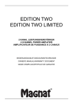
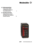
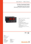
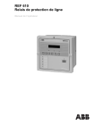
de Bedienungsanleitung 4-stellige Temperatur- und Frequenzanzeige mit Analogwertausgabe und Grenzwertüberwachung en 3 Operating instructions 4-digit temperature and frequency display with analogue-value output and threshold monitoring 15 PMX400/HZX 61001003/00/02.08 de PMX400/HZX Inhaltsverzeichnis Betrieb 4 Anschlüsse 8 Konfigurationssequenz 9 Ausgangskalibrierung 11 de PMX400/HZX • Betrieb Warnung: Bevor Sie das Gerät an die Stromversorgung anschließen, überprüfen Sie anhand der Typenbezeichnung, die Stromversorgung für das Gerät geeignet ist. Auswahl des Eingangssignaltyps Um das Gerät für einen bestimmten Spannungsimpuls zu konfigurieren, stellen Sie die in der Tabelle angegebenen Eingangsauslöse- und Eingangsrücksetzpegel ein. Wählen Sie für spannungsfrei Schaltvorgänge den Typ ‘Schließerkontakt’, da hier ein automatisches Entprellen der Kontakte erfolgt. Für alle anderen aufgeführten Eingabesignale ist die Einstellung hochpegelige Gleichstromsignale zu verwenden. Wenn Sie Unterstützung bei dieser Auswahl benötigen, wenden Sie sich telefonisch an den technischen Support. Konfiguration prüfen Zum Aufrufen des Prüfmodus entfernen Sie die Sicherheitsverbindung, und drücken Sie PGM. Der Prüfmodusaufruf muss innerhalb eines Zeitlimits (Timeout) von 10 s erfolgen. Konfiguration ändern Zum Aufrufen des Konfigurationsmodus kontaktieren Sie die Sicherheitsverbindung, und drücken Sie PGM. Daraufhin wird die Softwareversion angezeigt. Wenn Sie den Vorgang fortsetzen möchten, drücken Sie PGM erneut innerhalb von 10 s. Ausgelöste Alarme löschen Zum Quittieren eines ausgelösten Alarms drücken Sie die Taste des jeweiligen Kanals. Sirenen- und Gruppenalarme Kanal vier stellt die folgenden zwei zusätzlichen Alarmtypen zur Verfügung: •Sirenenalarm - wird durch Quittieren aller ausgelösten Alarme gelöscht •Gruppenalarm - wird nur gelöscht, wenn alle ausgelösten Alarme quittiert wurden und keine der Auslösebedingungen mehr bestehen (und diese außerhalb des Totbands liegen) Alarmsollwerte anzeigen Zum Überprüfen eines Sollwerts drücken Sie die dem Alarm zugeordnete Taste. Ist nach Drücken der Taste des Alarmkanals 4 auf der Anzeige der Code A4=Sr oder A4=gr zu sehen, dann ist der Kanal als Sirenenbzw. Gruppenalarm konfiguriert. Alarmsollwerte anpassen Drücken Sie zum Ändern eines Sollwerts die Taste PGM während der Wert angezeigt wird. Sie können nun den Wert mit Hilfe der Pfeiltasten ändern und die Änderung mit der Taste ENT speichern. Beachten Sie, dass vor Ausführen dieses Vorgangs die Sollwertsicherung deaktiviert werden muss. Blockschaltbild Stromversorgung Sensorversorgung (Ausgang) Signal von Frequenzquelle Physikalische Einheiten Analoger Ausgang (Optional) Alarm 1 Alarm 2 Alarm 3 (Optional) Alarm 4 Eingangstypen – + NAMURSensor PMX400/HZX 9 10 11 12 + Spannungsmpu sque e - NAMUR-Sensoren 10 11 PMX400/HZX Sg + Sensor 9 10 11 12 PMX400/HZX Extern gespe ste PNP-Open-Co ectorSensoren Spannungsmpu ss gna e E ngangstyp 3,0 V 2,4 V 25 mV 1,0 V 3,2 V 3,2 V 0,8 V -0,4 V -20 mV 11,9 V 6,6 V 4,3 V 380 mV 33,3 V 33,3 V 18,4 V 12,1 V 120 mV Aus ösung Rücksetzung Aus ösung 11,2 V 6V 3,7 V -20,5 V 12,75 V 12,75 V -2 V -8,4 V -400 mV Rückse zung Sonders gna Typ 3 Sonders gna Typ 2 Sonders gna Typ 1 Scha tkontakt Hochpege s gna e DC Beschre bung 5,6 V 1,6 V 100 mV -2,2 V 5,6 V 3,0 V Hochspannungse ngänge 1,2 V N ederspannungse ngänge 1,8 V PMX400/HZX PMX400/HZX Spannungsfre e Kontakte Extern gespe ste NPN-Open-Co ectorSensoren S gna Sensor – Sg a 9 10 11 12 PMX400/HZX b Spannungsfre e Kontakte 3-Drahtsensoren m t NPN-Open-Co ector-Ausgängen 9 10 11 12 PMX400/HZX 9 10 11 12 – Sg NPN-Typ 3-Draht-Sensor (O/C-Ausgänge) Sonders gna Typ 4 N edr gpege s gna e DC Hochpege s gna e AC N edr gpege s gna e AC 3,2 V Für 3-Drahtsensoren m t PNP-Open-Co ector-Ausgängen + Spannung (–ve) 9 10 11 12 Spannung (+ve) LOAC HIAC LOdC HIdC CoN SGL1 SGL2 SGL3 SGL4 – Sg PNP-Typ 3-Draht-Sensor (O/C-Ausgänge) + Spannung (–ve) S gna Spannung (+ve) • Anschlüsse Klemme Signal 1 Neutral / – 2 Phase / + 3 Ausgang + 4 Ausgang – 5 Wurzelkontakt (0V) 6 Ausgang Kanal 1 7 8 9 Ausgang Kanal 2 Stromversorgung Analoger Ausgang (Nur Option /AO) Alarmkanal 1 und 2 bestehen aus Halbleiterschaltern (max. Sperrspannung = 50 V DC/max. Durchlassstrom = 200 mA ) Mit 12 verbinden, um Zugriff auf den Konfigurationsmodus zu ermöglichen (bleibt normal unverbunden) Pull (Für Pull-up mit 12 verbinden/Für Pull-down mit 10 verbinden) 10 Signal – 11 Signal + 12 Geregelte 12 V DC ausgangsseitig (Masse ist intern mit Stift 10 verbunden) 13 Öffner 14 Wurzelkontakt 15 Schließer 16 Öffner 17 Wurzelkontakt 18 Schließer Eingänge Alarmkanal 3 (optional) Alarmkanal 4 (optional) • Konfigurationssequenz Einstellung S/W Version Anzeige v1.01 Instrument Type Freq Anzeige und Eingänge Display Intensity Input type Input frequency range Damping factor Display Range HIbr LObr Inp= LOAC H AC LOdC HIdC Con SGL1 SGL2 SGL3 SGL4 FdP= . FLO= 300 FHI= 1000 dF= 2 dP= . dLO= 0.0 dHI= 100.0 Beschreibung Å ì Softwareversion 1.01 (Hinweis: Diese Informationen beziehen sich nur auf die Versionen 1.00 bis 1.09) PMX400/HZX Hohe Leuchtstärke Niedrige Leuchtstärke Angabe des Eingangstyps Niedrigpegelsignal AC Hochpegelsignal AC Niedrigpegelsignal DC Hochpegelsignal DC Schaltkontakt Sondersignal - Typ 1 Sondersignal - Typ 2 Sondersignal - Typ 3 Sondersignal - Typ 4 Position des Dezimalpunkts Next Next Toggle Next ENT Accept Prev Accept Next Accept Shift Untergrenze des Eingangsfrequenzbereichs, z. B. 300 Hz Dec Inc Next Accept Obergrenze des Eingangsfrequenzbereichs, z. B. 1 kHz Dec Inc Next Accept Angabe des Dämpfungsfaktors Wert, z. B. 2 Dec Inc Next Accept Position des Dezimalpunkts Next Accept Shift Untergrenze des Anzeigebereichs, z. B. 0,0 Dec Inc Next Accept Obergrenze des Anzeigebereichs, z. B. 100,0 Dec Inc Next Accept Konfigurationssequenz (Fortsetzung) Analoge Ausgänge* Analogue Output Select AOPY AOPN Output action OP=d OP=r OPL= 4.00 OPH= 20.00 Aktiviert Deaktiviert (für PMX420 diese Option auswählen) Direkt Invertiert Accept Toggle Accept Inc Next Accept Maximaler Ausgangswert, z. B. 20,00 Dec Inc Hinweis: Zum Ändern des maximalen und minimalen Ausgangswerts müssen Sie die Ausgänge kalibrieren. Allgemeine Alarmeinstellungen* Aktivieren Alarms 1 & 2 A12Y Toggle Deaktivieren Select A12n Next Accept Analogue Output Range Minimaler Ausgangswert, z. B. 4,00 Toggle Dec Accept Aktivieren Toggle Accept Deaktivieren Sollwerte werden bei der Konfiguration fest SECy eingestellt Toggle Accept Setpoint security SECn Ändern der Sollwerte möglich Automatische Rücksetzung Alarm reset nOr Toggle Accept Manuelle Rücksetzung sequence rES Hinweis: Die Alarmeinstellungen werden nur angezeigt, wenn der relevante Alarmkanal aktiviert ist. Einstellungen des Alarmkanals 1* Normalerweise erregt A1nE Toggle Accept Coil energisation Normalerweise nicht erregt A1nd Alarms 3 & 4 Select A34Y A34n Alarm type A1=L A1=H SP1= 50.00 db1= 0.01 Setpoint value Typ ‘niedrig’ (unterhalb Sollwert aktiv) Typ ‘hoch’ (oberhalb Sollwert aktiv) Sollwert, z. B. 50,00 % Toggle Dec Inc Accept Next Accept Totband, Next z. B. 0,01 % Dec Inc Accept Zeitverzögerung (durch Setzen auf 0 s Next dL1= deaktivierbar) Timer delay Dec Inc Accept 20 z. B. 20 s Einstellungen des Alarmkanals 2* Wie Alarmkanal 1, verwendet aber die Codes A2nE, A2nd, A2=L,A2=H, SP2=, db2= und dL2=. Einstellungen des Alarmkanals 3* Wie Alarmkanal 1, verwendet aber die Codes A3nE, A3nd, A3=L,A3=H, SP3=, db3= und dL3=. Deadband value 10 Konfigurationssequenz (Fortsetzung) Einstellungen des Alarmkanals 4* Normalerweise erregt A4nE Coil energisation Normalerweise nicht erregt A4nd Toggle Accept Typ ‘niedrig’ (unterhalb Sollwert aktiv) Typ ‘hoch’ (oberhalb Sollwert aktiv) Alarm type Toggle Accept Gruppenalarm Sirenenalarm (nur manueller Rücksetzmodus) Hinweis: Bei Gruppen- und Sirenenalarmen werden die Sollwert-,Totband- und Timereinstellungen übersprungen Sollwert, Next SP1= Setpoint value z. B. 50,00 % Dec Inc Accept 50.00 A4=L A4=H A4=G A4=S db1= 10.00 dL1= 0 Totband, z. B. 10 % Dec Inc Next Accept Zeitverzögerung (inaktiv bei Setzen auf 0 s) z. B. keine Verzögerung Dec Inc Next Accept Kalibrieroptionen Calibrate Output? COPy COPn Save values SAVE Ausgangskalibrierung überspringen Toggle Accept Ausgänge kalibrieren Die Änderungen werden in der Konfiguration gespeichert, und das Gerät kehrt in den Normalbetrieb zurück. Deadband value Timer delay • Ausgangskalibrierung Allgemein Die analogen Ausgänge des PMX400HZX werden für einen bestimmten Ausgangsbereich und -typ kalibriert. Wenn Sie den Ausgangsbereich oder -typ ändern, müssen Sie anschließend die weiter unten angegebene Prozedur ausführen. Anforderungen an die Betriebsmittel • Ein präzises Digitalmultimeter (mit einer Genauigkeit von 0,05 mV und ±0,1 μA) 11 Klemmenbelegung für die Ausgangskalibrierung Kalibrierabschnitt Analoger Stromausgang Analoger Spannungsausgang Signaltyp Klemme mA-Ausgang + 3 mA-Ausgang – 4 V-Ausgang + 3 V-Ausgang – 4 Prozedur Hinweis: Die unten aufgeführte Prozedur bezieht sich auf die Kalibrierung des gängigen 4-20 mA-Signalbereichs. Wenn Sie für die Ausgänge einen anderen Signalbereich vorgegeben haben, werden Sie vom Gerät zur Angabe der gewählten Maximal- und Minimalwerte für den Ausgang aufgefordert. Wenn Sie das Gerät für einen Spannungsausgang kalibrieren, müssen Sie die Ausgangsspannung messen. Anzeige Aktion/Beschreibung Aktivieren Sie den Konfigurationsmodus des Gerätes, und scrollen Sie durch das Hauptmenü. COPn Drücken Sie ì oder Å. Drücken Sie ENT, um die Ausgangskalibrierung auszuwählen. COPy Schließen Sie zur Messung des Ausgangssignals das Multimeter an, und drücken OPL= Sie dann ENT. Justieren Sie den Ausgang (mittels der Taste ì oder Å), bis er den dargestellten 4.00 Wert aufweist. Wenn der Ausgang wie gewünscht eingestellt ist, drücken Sie ENT. Drücken Sie ENT. OPH= Justieren Sie den Ausgang (mittels der Taste ì oder Å), bis er den dargestellten Wert aufweist. Wenn der Ausgang wie gewünscht eingestellt ist, drücken Sie ENT. Fahren Sie mit der Konfigurationssequenz fort. Save Hinweis: Trennen Sie das Gerät nicht von der Netzspannung, solange die Speichernachricht angezeigt wird. 20.00 Auswahl des Ausgangssignaltyps Wenn der Ausgangstyp geändert werden soll, entfernen Sie die Rückwand, indem Sie die vier Clips, die die Rückwand fixieren, behutsam auseinander biegen, die Verbindung (auf der analogen 12 Ausgangsplatine) wie gewünscht vornehmen und alles wieder zusammensetzen. Ändern Sie dann den Ausgangssignaltyp in der Software: 1. Starten Sie die Konfigurationssequenz, und entfernen Sie, während die Softwareversionsnummer blinkend angezeigt wird, die Sicherheitsverbindung, und drücken Sie ENT. 2. In der Anzeige erscheint OP=C (bei Stromeingängen) bzw. OP=v (bei Spannungseingängen). Wählen Sie den korrekten Wert aus, stellen Sie die Sicherheitsverbindung wieder her, und drücken Sie ENT. 3. Das Gerät befindet sich jetzt im Konfigurationsmodus. Führen Sie die einzelnen Schritte zur Ausgangskalibrierung wie oben beschrieben aus. Auswahl des Hochspannungseingangs Zur Auswahl der Hochspannungseingänge, entfernen Sie die Rückwand, indem Sie die vier Clips, die die Rückwand fixieren, behutsam auseinander biegen, die Verbindung (auf der Hauptplatine) wie erforderlich vornehmen und alles wieder zusammensetzen. Analoge Ausgangsplatine Hochspannungseingang Normal Hoch Kontaktieren Sie die beiden Pfostenstecker für die Spannungsausgänge 13 Ca.1 mm anheben 1. Heben Sie den Verriegelungshebel vorsichtig mit einem Schraubendreher an, um die Rückwand zu lösen. 2. Ziehen Sie die Rückwand behutsam zurück, damit der Verriegelungshebel nicht wieder einrastet. 3. Wiederholen Sie den Vorgang für jeden Verriegelungshebel, bis die Rückwand nicht mehr fixiert ist. 14 en PMX400/HZX Contents Operation 16 Connections 19 Setup Sequence 20 Output calibration 22 15 en PMX400/HZX • Operation Warning: Check the power supply against the model number before applying power to the instrument. Input type selection To set up the unit for a particuar voltage pulse set the input trigger/ reset levels from the table shown. Use contact closure type for volt-free contacts as this includes debouncing. All other input types shown use the high level dc setting. If you need more help with this selection, please ring technical support. Reviewing the setup For review mode, disconnect security link and press PGM. A 10 s timeout applies for review mode. Changing the setup For set-up mode, connect security link and press PGM. The software version will be displayed. If you wish to continue, press PGM again within 10 s. Clearing tripped alarms You can acknowledge a tripped alarm by simply pressing the key for that channel. Siren and Group alarms Channel four has two additional alarm types: •Siren alarm, which you clear by acknowledging all tripped alarms •Group alarm, which will only clear when you have acknowledged all tripped alarms and all the trip conditions have cleared (and are outside the deadband) 16 Displaying the alarm setpoints To check a setpoint, simply press the key for that alarm. If the display shows A4=Sr or A4=gr when you press the alarm channel four button, you know it is set up as a siren or group alarm. Adjusting the alarm setpoints To change a setpoint, press the PGM key while the value is still on display. You will then be able to change the value using the arrows and save the change using the ENT key. Note that setpoint security must disabled for this to work. Block diagram Power Supply Sensor supply (Out) Signal from frequency source Engineering Units Analogue Output (Optional) Alarm 1 Alarm 2 Alarm 3 (Optional) Alarm 4 17 Input Types – + NAMUR sensor PMX400/HZX 9 10 11 12 + Vo tage pu se source - NAMUR sensors PMX400/HZX Sg + Sensor 9 10 11 12 PMX400/HZX Externa y powered PNP open co ec or sensors Vo tage pu se s gna s 10 11 nput type 5.6 V 5.6 V 3.0 V 2.4 V 25 mV Tr gger 1.6 V 1.0 V -2 2 V 3.2 V 3.2 V 0.8 V -0 4 V -20 mV Reset 11.9 V 6.6 V 4.3 V 380 mV 33.3 V 33.3 V 18.4 V 12.1 V 120 mV Tr gger 6V 3.7 V -20.5 V 12.75 V 12.75 V -2 V -8.4 V -400 mV Reset Spec a s gna type 3 Spec a s gna type 2 Spec a s gna type 1 Contact c osure H gh eve DC s gna s Low eve DC s gna s H gh eve AC s gna s Low eve AC s gna s Descr pt on 100 mV 3.0 V Low vo age nputs H gh vo tage nputs 1.2 V Vo t-free contacts Externa y powered NPN open co ector sensors. S gna 3-w re sensors w th NPN open co ector outputs 9 10 11 12 PMX400/HZX 9 10 11 12 PMX400/HZX – Sg NPN type 3-w re sensor (O/C outputs) Spec a s gna type 4 1.8 V PMX400/HZX 11 2 V 3.2 V 3-w re sensors w th PNP open co ector outputs + Power (–ve) 9 10 11 12 Power (+ve) LOAC HIAC LOdC HIdC CoN SGL1 SGL2 SGL3 SGL4 – Sg PNP type 3-w re sensor (O/C outputs) + Power (–ve) S gna Power (+ve) Sensor – Sg b Vo t-free contacts a 9 10 11 12 PMX400/HZX 18 • Connections Terminal Signal 1 Neutral / – 2 Live / + 3 Output + 4 Output – 5 Common (0V) 6 Channel one output 7 Channel two output 8 Link to 12 to allow access to set-up mode (normally left unconnected) 9 Pull (Link to 12 for pull-up/Link to 10 for pull-down) 10 Signal – 11 Signal + 12 Regulated 12 V DC out (Ov is connected to pin 10 internally) 13 Normally Closed 14 Common 15 Normally Open 16 Normally Closed 17 Common 18 Normally Open Power supply Analogue output (/AO option only) Alarm channels one and two are Solid state switches (max ‘off-state’ voltage = 50 V DC/max ‘on-state’ current = 200 mA ) Inputs Alarm channel three (optional) Alarm channel four (optional) 19 • Setup Sequence Setting Display S/W Version v1.01 Instrument Type Display and Inputs Freq Display Intensity HIbr LObr Inp= LOAC H AC LOdC HIdC Con SGL1 SGL2 SGL3 SGL4 FdP= . FLO= 300 FHI= 1000 dF= 2 dP= . dLO= 0.0 dHI= 100.0 Input type Input frequency range Damping factor Display range 20 Description Å ì S/W Version 1.01 (Note: this information only applies to versions 1.00 to 1.09) PMX400/HZX High brightness Low Brightness Introduces input type Low level AC signal High level AC signal Low level DC signal High level DC signal Contact Closure Special signal - type 1 Special signal - type 2 Special signal - type 3 Special signal - type 4 Decimal point position Next Next Toggle Next ENT Accept Prev Accept Next Accept Shift Input frequency range lower limit e.g., 300 Hz Dec Inc Next Accept Input frequency range upper limit e.g., 1 kHz Dec Inc Next Accept Introduces the damping factor Value, e.g., 2 Dec Inc Next Accept Decimal point position Next Accept Shift Display range lower limit e.g., 0.0 Dec Inc Next Accept Display range Upper limit e.g., 100.0 Dec Inc Next Accept Setup Sequence (continued) Analogue outputs* Analogue output select Output action Analogue output range AOPY AOPN OP=d OP=r OPL= 4.00 OPH= 20.00 Enabled Disabled (Select this option for PMX420) Toggle Accept A34Y A34n SECy SECn nOr rES Enable Disable Toggle Accept Setpoints fixed at setup Can change setpoints Toggle Accept Toggle Accept Toggle Accept A1=L A1=H SP1= 50.00 db1= 0.01 dL1= 20 Low type (active below setpoint) High type (active above setpoint) Toggle Accept Direct Reversed Output low value e.g., 4.00 Output high value e.g., 20.00 Note: to change the output high or low value you must calibrate the outputs. General Alarm settings* Enable Alarms 1 & 2 A12Y Disable Select A12n Alarms 3 & 4 Select Setpoint security Automatic reset Alarm reset Manual reset sequence Note: alarm settings are only shown if the relevant alarm channel is enabled. Alarm channel one settings* Normally energised A1nE Coil energisation Normally de-energised A1nd Alarm type Setpoint value Deadband value Timer delay Toggle Accept Toggle Accept Dec Inc Next Accept Dec Inc Next Accept Setpoint value e.g., 50.00 % Dec Inc Next Accept Deadband value e.g., 0.01 % Dec Inc Next Accept Timer delay (set to 0s to disable) e.g., 20 s Dec Inc Next Accept Alarm channel two settings* As alarm channel one, except uses A2nE, A2nd, A2=L,A2=H, SP2=, db2= and dL2=. Alarm channel three settings* As alarm channel one, except uses A3nE, A3nd, A3=L,A3=H, SP3=, db3= and dL3=. 21 Setup Sequence (continued) Alarm channel four settings* Coil energisation A4nE A4nd A4=L A4=H A4=G A4=S Normally energised Normally de-energised Toggle Low type (active below setpoint) High type (active above setpoint) Alarm type Toggle Group alarm Siren alarm (manual reset mode only) Note: for group or siren alarms, the setpoint, deadband and timer settings are skipped Setpoint value SP1= Setpoint value e.g., 50.00 % Dec Inc 50.00 Deadband value Timer delay db1= 10.00 dL1= 0 Calibration options Calibrate COPy Output? COPn Save values SAVE Accept Accept Next Accept Deadband value e.g., 10 % Dec Inc Next Accept Timer delay (set to 0 s to disable) e.g., no delay Dec Inc Next Accept Skip output calibration Toggle Accept Calibrate outputs Instrument is saving the changes to the setup and returning to normal operation • Output calibration General The PMX400HZX analogue outputs are calibrated for a specific output range and type. If you have changed the output range or type you must follow the procedure given below. Equipment requirements • An accurate digital multimeter (accurate to 0.05 mV and ±0.1 μA) Terminal Connections for output calibration Calibration Stage Analogue Current Output Analogue Voltage Output 22 Signal type Terminal mA output + 3 mA output – 4 V output + 3 V output – 4 Procedure Note: The procedure below shows calibration for the commonly used 4-20 mA format. If you have set the outputs to any other format, the unit will prompt you with the output high and low values you have chosen. If you are calibrating the unit for a voltage output you must measure the output voltage. When the Action/Description display shows Put the instrument in setup mode and scroll through the main menu COPn Press ì or Å Press ENT to select output calibration COPy OPL= 4.00 OPH= Connect the multimeter to measure the output signal, then press ENT Adjust the output (using the ì or Å keys) until the output is at the value shown When you are happy that the output is correct, press ENT Press ENT Adjust the output (using the ì or Å keys) until the output is at the value shown When you are happy that the output is correct, press ENT Continue with the setup sequence. Save Note: Do not remove the power while the save message is on display. 20.00 Output type selection If the output type needs to be changed, remove the back plate by gently prising apart the four clips that hold it in place, place the link (on the analogue output board) as apropriate and reassemble. Then change the output type in the software: 1. Start the set-up sequence and, while the software version number is flashing, remove the security link and press ENT. 2. The display will show OP=C (for current inputs) or OP=v (for voltage inputs). Select the correct value, replace the security link and press ENT. 3. The instrument is now in set-up mode. Scroll through and complete the output calibration procedure as described above. 23 High voltage input selection To select high voltage inputs, remove the back plate by gently prising apart the four clips that hold it in place, place the link (on the main board) as appropriate and reassemble. Analogue output board High Voltage Input Normal High Link both pairs of posts for voltage outputs Move about 1 mm 24 1. Gently move lug out a fraction with a screwdriver to release the backplate. 2. Pull the backplate back slightly to keep lug from clicking back into place. 3. Repeat with each lug until backplate comes loose. 25 26 27 Weidmüller Interface GmbH & Co. KG Postfach 3030 32720 Detmold Klingenbergstraße 16 32758 Detmold Tel. +49 5231 14-0 Fax +49 5231 14-20 83 [email protected] www.weidmueller.com 61001003/00/02.08