1
Mann Series
Process Instruments
Product Information
Mann Series Process Instruments
Signal Isolators
ISO – Signal Powered Isolators
4
TWI Series – Loop Powered Isolators
6
SFI/DFI – Auxiliary Powered Isolators
8
UTX Series – Programmable, Signal Isolator/Converters
10
MannPak MPC – Programmable, Auxiliary Powered, Signal Isolator/Converter
12
Signal Transmitters
ITXPlus Series – Universal, Loop Powered, Signal Isolator/Converters
14
FTX Series – Auxiliary Powered, Isolated, Signal Conditioners
18
STG – Auxiliary Powered, Strain Gauge Converter
26
Micromann AR Series – Universal, Auxiliary Powered, Dual Setpoint
28
Micromann UPI Series – Analogue to Frequency Converters
32
Process Alarms
DPA Series – Auxiliary Powered, Dual Setpoint, Alarm
36
Micromann R Series – Universal, Auxiliary Powered, Alarms
44
Multi–Channel Processing Modules
Micromann Multiplus Series – Multi–Input Signal Processing/Display Modules
48
Indicators and Auto/Manual Stations
PMX420 Series – Four Digit, Current/Voltage Displays
54
PMX400 Series – Four Digit, Programmable Displays with Alarms and Analogue Output 58
DI350 – 3+1/2 Digit Indicator
62
PM450 – 4+1/2 Digit Indicator
64
LPD350 – 3+1/2 Digit, Loop Powered, Indicator
66
LPD450F – Field Mount, Loop Powered, Display
68
AMS400A – Universal Auto/Manual Station
70
Totalisers
PTX800 Series – Panel Mount, Totalisers/Counters
72
Calibrators
Portacal 275 – Handheld Signal Source and Loop Calibrator
76
Portacal 1000 – Current/Voltage Instrument Calibrator
78
Appendix
Worldwide Activities
80
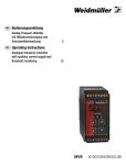
Signal Isolators
ISO – Signal Powered Isolators
The ISO provides an isolated 4-20 mA
signal from any 4 – 20 mA loop with sufficient drive. It provides a simple way to fix
unexpected problems caused by ground
loops and high common mode noise.
• Provides complete isolation
• Signal powered
• Suitable for loads up to 400 Ω
•Removable, screw-type, terminal
blocks
• Compact metal housing
Signal Isolators
ISO
4 – 20 mA
Connections
Technical Data
Input
Type
Input resistance
Minimum input resistance
Output
4 – 20 mA
200 Ω + load across output
300 Ω
Type
Output load range
Ripple
Power supply
4 – 20 mA
0 – 400 Ω
< 20 mV peak to peak at maximum load and span
Type
Voltage drop
Adjustments
Input loop signal powered
4 V fixed drop + drop across output
Type
Trim
Load
General
20-turn potentiometers
To trim output range
Compensates for low output loads
Linearity
Repeatability
Storage temperature
Operating temperature
Relative humidity
Temperature drift
Long term drift
Frequency response
Response time
Noise Immunity
Isolation
Housing
Typically ± 0.3 % of span
± 0.05 % of span
– 25 to + 70 °C
0 to 60 °C
0 – 95 % (non-condensing)
Typically 0.02 % span/°C
0.1 % per 10,000 hours
– 3 dB point = 5 Hz
500 mS for 10 – 90 % output change
130 dB CMRR (1.5 kVrms limit)
1.5 kVrms for 60 s (AC & DC)
Type
Dimensions
Weight
Connection type
Registered Design Anodised Aluminium Enclosure
See diagram
240 g
Plug in terminal blocks with screw connections
Terminal
Signal
1
2
3
4
5
5
7
8
9
10
Case
Signal + ve
Signal – ve
Input signal
Not Used
Output + ve
Output – ve
Output signal
Not Used
Earthing is via a stud on lower side of case
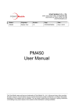
Dimension Drawing
MM4OP(ATMM¼$).%.
MM'2AILMM¼$).%.
4OSURFACEINCLUDINGRAIL
Ordering Information
Type
ISO 4-20 mA
Cat. No.
7940010235
Signal Isolators
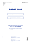
TWI Series – Loop Powered, Isolators
TWI-1 Single Channel
TWI-2 Dual Channel
The TWI-1 and TWI-2 are single and dual
channel, loop powered isolators.
• Current or Voltage inputs
• Powered from 4 – 20 mA output loop
• Highly accurate (± 0.1 % of span)
• Front panel zero and span adjustment
• Complete Isolation to 1.5 kV (ac and dc)
•Removable, screw-type, terminal
blocks
• Compact metal housing
Signal Isolators
TWI-1
4 – 20 mA
TWI-2
4 – 20 mA
TWI-1 Connections
Technical Data
Terminal
Signal
1
2
3
4
5
6
Case
Signal +ve
Not used
Input
Signal – ve
Signal +ve
Not used
Output
Signal – ve
Earthing is via a stud on lower side of case
TWI-2 Connections
Inputs
Type
Ranges
Input impedance
Outputs
DC milliamp or voltage
4 – 20 mA or 0 – 10 V
27 Ω (4 – 20 mA inputs) or ≥ 1 MΩ (0 – 10 V inputs)
Type
Ripple
Max loop load
Power Supply
4 – 20 mA loop powered
less than 10 µA peak to peak
[(Vs – 12) ⁄ 0.02] Ω (Typically 600 Ω at 24 V DC)
Type
Line voltage effect
12 – 45 V DC loop powered
less than 0.05 % of span change for 10 V change in supply
over 12 – 45 V DC range
Adjustments
Type
Span
Zero
General
22-turn potentiometers
± 25 % of nominal span
± 25 % of nominal span
Linearity
Repeatability
Storage temperature
± 0.1 % of span
± 0.02 % of span
– 25 to + 70 °C
Operating temperature
Relative humidity
Temperature drift
Long term drift
Input response
Frequency response
Noise Immunity
– 10 to 60 °C
0 – 95 % (non-condensing)
< 0.02 % span per °C
< 0.1 % per 10,000 hours
200 mS (from 10 % to 90 % of span)
– 3 db point = 5 Hz
120 dB CMRR (1.5 kVrms limit)
40 db series mode noise rejection @50 Hz
Terminal
Signal
1
2
3
4
5
6
7
8
Case
Signal +ve
Input Channel one
Signal – ve
Signal +ve
Input Channel two
Signal – ve
Signal +ve
Output Channel one
Signal – ve
Signal +ve
Output Channel two
Signal – ve
Earthing is via a stud on lower side of case
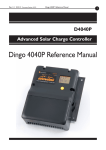
Dimension Drawing
2)'(4(!.$3)$%6)%7
MM
4/06)%7
7IDTH
47)MM
47)MM
Isolation
Isolation (Input to Output to Earth)
Housing
1.5 k Vrms for 60s (AC & DC)
Type
Dimensions
Weight
Registered Design Anodised Aluminium Enclosure
See diagram
TWI-1 205 gm
TWI-2 238 gm
Plug in terminal blocks with screw connections
Connection type
%FFECTIVEDEPTH
MM4OP(ATMM$).%.
MM'2AILMM$).%.
4OSURFACEINCLUDINGRAILMOUNTINGPLATE
Ordering Information
Single Channel
4-20 mA Input
TWI-1 4-20 mA
0-10V Input
TWI-1 0-10 V
Type (Model Input)
TWI-1 4-20 mA
TWI-2 4-20 mA
TWI-1 0-10 V
TWI-2 0-10 V
Dual Channel
TWI-2 4-20 mA
TWI-2 0-10 V
Cat. No.
7940010159
7940010171
7940011660
7940012011
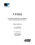
Signal Isolators
SFI/DFI – Auxiliary Powered, Isolators
SFI Single Channel, Isolator
DFI Dual Channel, Isolator or Signal
Splitter
The SFI is a single channel, auxiliary powered, isolator for current/voltage signals.
The DFI combines two isolators, which
can be used separately or as a signal
splitter.
• Single and dual channel versions
• Power for active input devices
• Highly accurate (± 0.1 % of span)
• LED status indication
• Bipolar inputs
• Switch selectable input format
• Front panel zero and span adjustment
• Complete Isolation to 1.5 kV (ac and dc)
• DC powered
•Removable, screw-type, terminal
blocks
• Compact metal housing
Signal Isolators
The standard package has a single
24 V DC output to drive a loop powered
transmitter as input. The second power
supply output (on DFI channel two) is
standard.
Input channel one, Input channel two,
Output channel one, Output channel two
and the power supply are all fully isolated
from one another.
SFI
Technical Data
Connections
Terminal
Signal
Switch selectable current/voltage format
4 – 20 mA, 0 – 20 mA, 0 – 10 V, – 10 to +10 V
Other ranges on request
22 Ω (current inputs) or 1 MΩ (Voltage inputs)
One 24 V DC (to 25 mA) per channel
1
2
3
4
5
6
24 V DC (out)
Current +ve
Common – ve
Voltage +ve
24 V DC (out)
Current +ve
Current/voltage format (as ordered)
4 – 20 mA or 0-20 mA (into 0 – 1.5 kΩ load)
0 – 10 V (minimum load 5 kΩ)
1 – 5 V (minimum load 2.5 kΩ)
Other ranges on request
22 Ω (current inputs) or 1 MΩ (Voltage inputs)
7
8
9
10
11
12
13
14
15
16
Case
Inputs
Type
Ranges
Input impedance
Power supply (out)
Outputs
Type
Ranges
Input impedance
Power Supply
Type
DC
Power Usage
DFI
DC powered
12 – 50 V DC
4.5 W at 24 V DC (fully loaded including sensor power supply)
3.60 W (fully loaded with no sensor power supply)
Input channel one
Input channel two
Common – ve
(DFI only)
Voltage +ve
Neutral ( – ve)
Power supply
Live (+ve)
Not used
Output +ve
Output channel one
Output – ve
Not used
Output channel two
Output +ve
(DFI only)
Output – ve
Earthing is via a stud on lower side of case
Adjustments
Type
Span
Zero
General
20-turn potentiometers
± 25 % of span
± 25 % of span
Accuracy
Repeatability
Storage temperature
Operating temperature
Relative humidity
Temperature drift
± 0.1 % of span
± 0.05 % of span
– 25 to +70 °C
0 to 60 °C
0 – 95 % (non-condensing)
Typically 0.005 % span/°C
Worst case 0.02 % span/°C
0.1 % per 10,000 hours
200 mS (from 10 % to 90 % of span)
– 3 db point = 5 Hz
100 dB CMRR (1.5 kVrms limit)
1.5 kVrms for 60 s (AC & DC)
Long term drift
Input response
Frequency response
Noise Immunity
Isolation
Housing
Type
Dimensions
Weight
Connection type
Registered Design Anodised Aluminium Enclosure
See diagram
0.5 kg
Plug in terminal blocks with screw connections
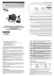
Dimension Drawing
RIGHT HAND SIDE VIEW
97 mm
TOP VIEW
46 mm
Effective depth :
120mm (Top Hat 35mm +/- 0.3, DIN 46277-3, EN 50022)
125mm (G - Rail 32mm +/- 0.3, DIN 46277-1, EN 50035)
To surface (including rail/mounting plate)
Ordering Information
Type (Model Input/Ouput/Supply)
SFI 0-10 V/4-20 mA/12-50 V DC
SFI 4-20 mA/4-20 mA/12-50 V DC
DFI 0-10 V/4-20 mA/12-50 V DC
DFI 4-20 mA/4-20 mA/12-50 V DC
Cat. No.
7940016083
7940010212
7940012275
7940010167
Note: For other ranges please specify Model 1/2/3 where:
1 = Input, 2 = Output, 3 = Supply
Signal Isolators
UTX Series – Programmable, Signal Isolator/Converters
UTXSCI Current/Voltage Inputs
UTXSRT Square Root Extractor
The UTX Series signal isolator/converters
accept voltage or current inputs from field
devices and provide an isolated voltage
or current output.
• Auxiliary Powered
•Models to suit linear or square law
signals
• 24 V DC power for active input devices
• Programmable digital filter
• Simple secure calibration method
•Easily calibrated to suit most input and
output ranges
•Absolute value, reverse action, high
limit and low limit functions
• LED status indication
• Complete Isolation to 1.5 kV (ac and dc)
•Removable, screw-type, terminal
blocks
• Compact metal housing
10
Signal Isolators
You can change the switch settings and
supply different voltages/currents during
calibration to change the set-up.
The switch settings allow you to select:
• Low limit clamp
• High limit clamp
• Absolute value function
• Digital filter constant
• Direct or reverse acting output
• Output type (current/voltage)
You can select the input type (current or
voltage) by connecting the input signal to
different terminals. Both the input and
output ranges are determined by the
calibration.
There are two models in the UTX Series.
The UTXSCI has proportional outputs for
linear signals.
The UTXSRT accepts inputs from square
law devices and produces an accurate
linearised output. It also incorporates a
low signal cut-out to prevent accumulated
errors at low flow rates. The cut-out level
is switch selectable.
UTX Series Connections
Technical Data
Terminal
Input
Type
Range limits
Minimum recommended span
Transducer supply
Input Impedance
Resolution
Output
Analogue current or voltage signals
Inside the range ± 22.00 mA or ± 11.00 V
10 % of nominated range
24 V DC (to 25 mA) output
22 Ω (current inputs) or
1 MΩ (voltage inputs)
2 µA/1 mV per bit
Type
Current drive
Voltage drive
Range limits
Minimum recommended span
Resolution
Output ripple
Functions
Programmable current/voltage
Up to 900 Ω load
True voltage source (up to 20 mA)
Inside the range 0.00 – 22.00 mA or 0.00 – 11.00 V
2 mA or 1 V
2 µA/1 mV per bit
Less than 20 mV P/P
Low limit
Clamps the output at calibrated output zero when the input
goes below the calibrated input zero level
Clamps the output at calibrated output full scale when the
input goes above the calibrated input maximum.
Performs absolute value calculations, e.g., a unit calibrated
to give a 0 – 10 V output for a 5 – 10 V input will give a 10-0 V
output for a 0 – 5 V input.
High limit
Absolute value function
UTXSCI / UTXSRT
Signal
1
24 V DC (out)
2
Current +ve
Input signals
3
Common – ve
4
Voltage +ve
5
Not Used
6
7
Security Link
8
(link if you want to calibrate the instrument)
9
Neutral ( – ve)
Power supply
10
Live (+ve)
11
12
Not Used
13
14
Output +ve
15
Current – ve
Output Signals
16
Voltage – ve
Note: Earthing is via a stud on lower side of case
Dimension Drawing
RIGHT HAND SIDE VIEW
Power Supply
Type
DC
Power usage
Performance
DC powered
12 – 50 V DC (other voltages on request)
6 W at 24 V DC
Linearity
Storage temp
Operating temp
Temp drift
Long term drift
Reponse (10-90 %)
Setup retention
Noise immunity
Housing
Better than ± 0.1 % typical – dependant on input span
– 25 to +70°C
0 to 60 °C
< 0.02 % span per °C
0.1 % per 10,000 hours
Programmable in 8 steps (from 250 ms to 10 s)
100 years
120 dB CMRR (1.5 kVrms limit)
Type
Dimensions
Connection type
Weight
Registered Design Anodised Aluminium Enclosure
See diagram
Plug in terminal blocks with screw connections
0.5 kg
97 mm
TOP VIEW
46 mm
Effective depth :
120mm (Top Hat 35mm +/- 0.3, DIN 46277-3, EN 50022)
125mm (G - Rail 32mm +/- 0.3, DIN 46277-1, EN 50035)
To surface (including rail/mounting plate)
Ordering Information
Type (Model Supply)
UTXSCI 12-50 V DC
UTXSRT 12-50 V DC
Cat. No.
7940010172
7940017913
Note: Other ranges available on request. Please specify as
UTX/1/2 where:
1 = SCI for linear signals or SRT for square law signals
2 = Power Supply Voltage
11
Signal Isolators
MannPak MPC – Programmable, Auxiliary Powered,
Signal Isolator/Converter
The MannPak MPC signal isolator/converters accept voltage or current inputs
from field devices and provide an isolated
voltage or current output.
• Auxiliary Powered
•24 V DC power for loop powered input
devices
• Simple secure calibration method
•Calibration allows for input to output
scaling and reverse action if required
• LED status indication
•Complete input to output to power
supply Isolation to 1.5 kV (ac and dc)
• Compact 22.5 mm wide housing
• Mounts on 35 mm ‘Top Hat‘ and G-rail
12
Signal Isolators
The MannPak MPC 4-wire DC Input
Isolator provides 3-way isolation for all
standard DC milliamp and voltage signals,
with better than 0.1 % accuracy (typically
0.05 %). For simple elimination of ground
loops where auxiliary power is available.
Features
• Compact 22.5 mm wide housing
• 1500 Vrms 3-way isolation
•24 V DC field supply for loop powered
transmitter inputs
• 9-60 V DC power supply
• CE approved (CSA & UL pending)
• Scaleable input to output
• Output action direct or reverse
Technical Data
MannPak MPC
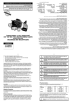
Installation Diagram
Input
&YUFSOBM4PVSDF
TJH
HOE
4VQQMZ%$
@
@
N"7JOQVU
TJH
@
7ED
N"
XJSF5Y
1 2 3
0VUQVUWF
Linearity
Storage temp
Operating temp
Temp drift
Long term drift
Setup retention
Noise immunity
Response time 10 % – 90 %
Housing
Better than ± 0.1 % (typical ± 0.05 %)
– 25 to +70 °C
0 to 60 °C
< 0.05 % span per °C
0.1 % per 10,000 hours
100 years
120 dB CMRR (1.5 kVrms limit)
< 220 ms
Type
Dimensions
Connection type
Weight
Approvals
Dual DIN rail mount
75.5 x 22.5 x 119 (max)
Screw connections 22 – 12 AWG (0.5-4.0 sq mm)
0.2 kg
CE
UL/CSA
EN61326:1997 including ammendment 1 and 2
Pending
*OWF
2 W at 24 V DC
*OWF
0VUQVUWF
Power usage
Performance
0VUWF
DC powered
9 – 60 V DC
QXSWF
Type
DC
0VUWF
Current/voltage (Jumper select)
Up to 1 kΩ load
Loads >= 500 kΩ
Inside the range 0.00 – 22.00 mA or 0.00 – 11.00 V
2 mA or 1V
3.5 µA/1.76 mV per bit
Less than 20 mV P/P
QXSWF
Type
Current drive
Voltage drive
Range limits
Minimum recommended span
Resolution
Output ripple
Power Supply
QXSWF
*OWF
*OWF
NBOO1BL*TPMBUPS
QXSWF
6 5 4
0VUWF
Resolution
Output
Analogue current or voltage signals (Jumper select)
Inside the range 0 – 22.00 mA or 0 – 11.00 V
10 % of nominated range
20 mA @ 24 V DC output (safety limited to 32 mA)
100 Ω (current inputs) or
>1 MΩ (voltage inputs)
3.5 µA/1.76 mV per bit
0VUWF
Type
Range limits
Minimum recommended span
Transducer supply
Input Impedance
.PVOUJOH
%FFOFSHJTFCFGPSFDMFBOJOH
Ordering Information
Type
MannPak MPC
Cat. No.
7940015297
13
Signal Transmitters
ITXPlus Series – Universal, Loop Powered,
Signal Isolator / Converters
ITXPlus Rail mount
CBX100 Cable interface
• Universal Input
• Converts, filters and and isolates most
common signals and sensor types
• Fully isolated
• Loop powered
• PC Programmable
• Cost effective
• Compact
• Rail mount
• Automatic CJC for thermocouple inputs
•Automatic lead length compensation
for RTD inputs
• Sensor burnout detection
• Preset and user-defined linearisation
14
Signal Transmitters
The ITXPlus is a truly universal, compact, loop powered, isolated, signal converter. You can program it to suit most input
signals. It will measure, convert, filter, and isolate the signal and
provide you with an industry standard 4 – 20 mA output.
For linear temperature measurement, you can use any
thermocouple or RTD type with the default tables. The ITXPlus
will also accept resistance, potentiometer (position), millivolt,
milliamp or voltage signals.
You don’t even need to recalibrate to change the input type.
The program has inbuilt square root, linear, x1.5 and x2.5
transfer functions or you can set up a table of input/output
values to characterise any unusual curve.
The set-up software is easy to use, works on any PC, and
allows you to completely configure the unit – even while the loop
is operating.
The cable interface (sold separately) provides full isolation
between standard serial ports on your PC and the transmitter
(order as CBX100).
Technical Data
Power Supply
Thermocouple Inputs
Inputs
Type
Type
Standard
B
C
E
IEC584
J
K
L
DIN 43710
N
R
IEC584
S
T
W3
ASTM
W5
E98890
Other Thermocouple types
Cold Junction Compensation
Sensor error detect
Milliamp
2, 3, 4-wire RTD
Voltage
Millivolt
Type
Standard
Pt 100
DIN 43710
Pt 100
JIS
Pt 200
DIN 43710
Pt 200
JIS
Ni 120
DIN 43710
Cu 100
DIN 43710
Cable resistance per wire
Sensor Current
Sensor cable resistance effect (3/4 wires)
Resistance
Accuracy
Thermocouple, RTD, Milliamp, Voltage,
Millivolt, Resistance
Lower limit Upper limit
Min Span
400 °C
1828 °C
200 °C
0 °C
2000 °C
– 100 °C
1000 °C
50 °C
– 100 °C
1200 °C
– 180 °C
1372 °C
– 100 °C
900 °C
– 180 °C
1300 °C
100 °C
– 50 °C
1760 °C
200 °C
– 50 °C
1760 °C
– 200 °C
400 °C
50 °C
0 °C
2300 °C
200 °C
You can define 2 – 101 point linearising
curves for other types
Better than ± 1.0 °C
Yes
– 10 mA to + 20 mA into 40 Ω (min span 1 mA)
– 5 V to + 10 V into 2 MΩ (min span 0.5 V)
– 100 mV to +200 mV into 2 MΩ (min span 4 mV)
Lower limit Upper limit
Min Span
– 200 °C
850 °C
– 200 °C
630 °C
– 200 °C
850 °C
50 °C
– 200 °C
630 °C
– 80 °C
320 °C
– 100 °C
260 °C
100 °C
5 Ω Maximum
0.1 mA
< 0.002 Ω per Ω of cable resistance
Type
Operating voltage
Voltage effect
Output
Output loop powered
10–40 V DC
0.005 % per volt
Type
Ripple
Maximum loop load (4 – 20 mA loop)
4 – 20 mA (limited to 22 mA)
less than 20mV p/p at max load and span
[(Vs – 10) ∕ 0.02] Ω (Typically 700 Ω at 24 V DC)
Direct or reverse
Output Action
Performance
Storage temp
Operating temp
Relative Humidity
Temp drift
Long term drift
Update time
Digital filter range
EMI effect
Approvals
Response time
Noise immunity
Common mode
Series mode
Isolation
Housing
– 20 to +70 °C
– 10 to +70 °C
10 – 90 % (non-condensing)
Typically 0.01 % span per °C
0.1 % per 10,000 hours
20 – 200 mS
1 – 100
Better than ± 0.5 % full scale
Electromagnetic compatability
AS/NZS 3548/2064
Typically 200 ms for 10 – 90 % output change
120 dB CMRR (1.5 kVrms limit)
40 dB at 50 hz
1.5 kVrms for 60 s (AC & DC)
Type
ITXPlus
Weight
ITXPlus
Dimensions
Digital communications
Compact DIN rail mount
83 g
See mechanical drawings
Type
Equipment required
For set-up and calibration only
CBX100 Interface module
IBM PC
0 to 10 kΩ (min span 10 Ω)
Input Type
E,J,K,L,N,T,U
Span
< 500 °C
> 500 °C
B, C, R, S, W3,
W5
mV, V, mA
RTD
Resistance
Temp coefficient
± 0.02 °C per °C ambient
± 0.01 %Full scale per °C
ambient
± 0.02 °C per °C ambient
All
N/A
Accuracy
Better than ± 1.0 °C
Better than ± 2.0 °C
Better than ± 0.1 % FS
Better than ± 0.5 °C
Better than ± 0.1 % FS
15
Signal Transmitters
ITX+
CBX100
ITX Plus Connections
Termnal
Signal
5
Loop-ve
Output(4-20mA)
6
Loop+ve
NoticepolarityofoutputsisreversedcomparedtoITXPlusH
1
Signal+ve
Thermocouple
2
Signal–ve
1
Asense
3
A
4-wireRTD
2
B
(orResistance)
4
Bsense
1
Asense
3-wireRTD
3
A
(orResistance)
2
B
3
A
2-wireRTD
2
B
(orResistance)
1
Signal+ve
Voltaqe(mVorV)
2
Signal–ve
1
Signal+ve
Current(mA)
2
Signal–ve
3
A
1
Wiper
Potentiometer
2
B
CBX100 Interface kit
• ConnectsITXPlustoPCforSet-upand
calibration
• Rechargeablebattery(allowsforabout
8hrsuse)
• ProvidesfullisolationbetweenPCand
ITXPlus
• Softwareallowsyoutostoretheset-up
ofeachtransmitterondisk
Connection Diagram
Mechanical Drawing
)480LUS
/UTPUT
)NPUT
0#
#"8
.OTE©DISCONNECT©BATTERY©CHARGER
BEFORE©USING©#"8
Ordering Information
Ordering Information
Type (Model Input/Output/Supply)
Cat. No.
7940016563
ITX+4–20mA/4–20mA/12–45VDC
Defaultinputrangeis4–20mA.Forotherspleasespecify.
16
Type
CBX100
Cat. No.
7940010208
Signal Transmitters
17
Signal Transmitters
FTX Series – Auxiliary Powered, Isolated, Signal Conditioners
FTXDMA, FTXDCV, FTXDMV, FTXPOT
FTXRTD, FTXRTL, FTXTCX/P, FTXTCL
FTXAVX, FTXRES, FTXHLS
FTXMAS, FTXDRT, FTXCND
The FTX series signal conditioners isolate
and convert measurement signals to
standard current/voltage format with a
high degree of accuracy.
• Models available to suit most plant
based measurements
• Complete input to output to power
supply Isolation to 1.5 kV (ac and dc)
• Switch selectable analogue output
ranges
• Highly Accurate (0.1 %)
• DC powered
• Non-interacting zero and span controls
• Front panel mounted test points for
output signal monitoring
• Wide zero and span adjustments
• Removable, screw-type, terminal
blocks
• Compact metal housing
18
Signal Transmitters
The FTX Series of transmitters can be
manufactured to accept almost any
industrial input and convert the measurement to a standard industrial current or
voltage output.
Three port isolation is standard: eliminating ground loops and ensuring the FTX
will work with any receiving device that
can accept a sourced output.
The input is set up by means of a “personality card” which conditions the input
and converts it to a linear smoothed
isolated output.
The output can drive 20 mA into any load
from 0 – 1000 ohms and has a true voltage sourcing capability even into loads as
low as 1000 ohms.
The output type and range are set by
user adjustable DIP switches. A whole
host of special output ranges have been
developed over time including bipolar
voltage and current outputs.
Technical Data
General Connection Diagram
Output
Type
Current ranges
Voltage ranges
Ripple
Power Supply
FTX
For input connections see each separate model
Switch selectable analogue current and voltage
0 – 20 mA into 0 – 1 KΩ load
4 – 20 mA into 0 – 1 KΩ load
Note: see also high output drive capability (/HSO) option
True voltage source up to maximum current of 20 mA
0 – 5 V DC
0 – 10 V DC
1 – 5 V DC
– 10 V to +10 V (see BP option)
less than 20 mV P/P at maximum load & span
Type
DC
Custom Power Supply Voltages
Power Usage
Adjustments
DC powered
24 V DC (20 to 28 V DC) / Other voltages on request
See /CPS option below
3 W at 24 V DC
Type
Span
Zero
General
20-turn potentiometers
± 25 % of nominal span
± 25 % of nominal span
Accuracy
Linearity
Repeatability
Storage temperature
Operating temperature
Relative humidity
Temperature drift
Long term drift
Frequency response
Response time
Noise Immunity
Isolation
Housing
Typically ± 0.1 % of span
Typically ± 0.1 % of span
± 0.05 % of span
– 25 to +70 °C
0 to 60 °C
0 – 95 % (non-condensing)
Typically 0.02 % span/°C
0.1 % per 10,000 hours
– 3 dB point = 5 Hz
200 mS for 10 – 90 % output change
130 dB CMRR (1.5 kVrms limit)
1.5 kVrms for 60 s (AC & DC)
Type
Dimensions
Weight
Connection type
Options
Registered Design Anodised Aluminium Enclosure
See diagram
0.45 Kg
Plug in terminal blocks with screw connections
CPS/[Voltage Required] Custom Power Supply
HOD High Output Drive capability
BP Bipolar outputs
NSO Non standard output range
48 V DC
1500 Ω for current outputs – 24 V DC powered versions only
– 10 V to +10 V
Specify range
N(-)
L(+)
10
1
2
3
4
5
6
11
14
PS
Out
13
Input
Earthing is via a stud on
the lower side of the case
Dimension Drawing
RIGHT HAND SIDE VIEW
96 mm
TOP VIEW
46 mm
Effective depth :
120mm (Top Hat 35mm +/- 0.3, DIN 46277-3, EN 50022)
125mm (G - Rail 32mm +/- 0.3, DIN 46277-1, EN 50035)
To surface (including rail/mounting plate)
Switch Selection
Output
Switch bit
C/V
1
2
3
4
5
6
7
8 Link
0 – 20 mA
C
C
C
O
C
O
C
O
C
4 – 20 mA
O
C
O
O
C
O
C
O
C
0 – 5V
C
C
C
C
O
C
O
O
V
1 – 5V
O
C
O
C
O
C
O
O
V
0 – 10V
C
O
C
C
O
C
O
O
V
2 – 10V
O
O
O
C
O
C
O
O
V
For switch settings C = Closed/On & O = Open/Off
19
Signal Transmitters
FTX Series – Auxiliary
Powered, Isolated, Signal
Conditioners
DC Current/Voltage Inputs
FTXDMA
FTXDMV
DC millivolts
• For DC millivolt signals
• High input impedance
• Accepts bipolar inputs
DC milliamps
• For DC milliamp signals
• Low input impedance
• Accepts bipolar inputs
(-)
5 or 6
(-)
(+)
10
Current source
11
Out
Input
6
Earthing is via a stud on
the lower side of the case
4
(-)
11
Out
Input
(+)
10
Voltage Source
14
PS
mV
13
DC voltage
• For DC voltage signals
• High input impedance
• Accepts bipolar inputs
(+)
10
Voltage Source
14
PS
mA
4
FTXDCV
6
11
V
13
14
PS
Out
4
Input
13
Earthing is via a stud on
the lower side of the case
Earthing is via a stud on
the lower side of the case
Technical Data
Inputs
Input Type
Standard ranges
DC milliamps
0 – 1 mA into 100 Ω
1 – 5 mA into 22 Ω
0 – 10 mA into 10 Ω
0 – 50 mA into 10 Ω
4 – 12 mA into 10 Ω
12 – 20 mA into 10 Ω
0 – 20 mA into 10 Ω
4 – 20 mA into 10 Ω
– 20 to +20 mA into 10 Ω
Note: other ranges are available on request.
From 10 Ω (see above)
20 µA to 500 mA
DC millivolts (< 500 mV)
As ordered
DC voltage (>500 mV)
0 – 1 V into 10 MΩ
0 – 5 V into 500 KΩ
0 – 10 V into 1 MΩ
0 – 20 V into 2 MΩ
1 – 5 V into 500 KΩ
2 – 10 V into 1 MΩ
– 10 V to +10 V into 2 MΩ
Note: other ranges are available on request
10 MΩ
2 to 100 mVDC (see also LS option)
Input offset range
Options
0 – 500 % of span (see HO option)
0 – 500 % of span (see HO option)
Up to 2 MΩ (see above)
0.1 to 300 V DC (see also HV option)
Note: for voltages above 300 V DC use the
external attenuator – Attenuator
0 – 500 % of span (see HO option)
HO High Offset
LS Low Span
HV High voltage option
For zero value > span
For zero value > span
For spans from 2 mV to 8 mV
Input Impedance
Input span range
For zero value > span
For spans > 60 V
Ordering Information
20
Type
Cat. No.
(Model Input/Output/Supply)
7940011588
FTXDMA 4 – 20 mA/
0 – 10 V DC/24 V DC
7940011716
FTXDMA 4 – 20 mA/
4 – 20 mA/24 V DC Type
Cat. No.
(Model Input/Output/Supply)
7940011965
FTXDMV 0 – 50 mV/
4 – 20 mA/24 V DC
Type
Cat. No.
(Model Input/Output/Supply)
7940014960
FTXDCV 0 – 10 V/
4 – 20 mA/24 V DC
7940014327
FTXDCV 0 – 5 V/
4 – 20 mA/24 V DC
Note: For other ranges please specify FTXDMA 1/2/3 where:
1 = Input current range
2 = Output Signal
3 = Power Supply Voltage
Note: For other ranges please specify FTXDMV 1/2/3 where:
1 = Input current range
2 = Output Signal
3 = Power Supply Voltage
Note: For other ranges please specify FTXDCV 1/2/3 where:
1 = Input current range
2 = Output Signal
3 = Power Supply Voltage
Signal Transmitters
FTX Series – Auxiliary
Powered, Isolated, Signal
Conditioners
AC Current/Voltage Inputs
FTXAVX
AC voltage
• Class 0.5 device
• Optional “true RMS” input
circuit for non-sinusoidal
signals
(-)
AC Voltage Source
6
^
(+)
10
11
V
4
14
PS
Out
Input
13
Earthing is via a stud on
the lower side of the case
Technical Data
Inputs
Input Type
Input waveform (Standard units)
Standard ranges
Input Impedance
Input span range
Input offset
Adjustments
AC Voltage
True sine wave input with a frequency in
the range 47 – 63 Hz (see /RMS option for
other waveforms)
As ordered
Dependant on input > 1 MΩ
8 mV to 300 V AC (see also HV option)
Note: for voltages above 300 V AC use the
external attenuator – NTX/H/Attenuator
0 – 500 % of span (see HO option)
Input span adjustment
Input zero adjustment
General
Instrument Class
Linearity
Frequency response
Response time
Weight
Isolation
Options
0.5
Typically ± 0.2 % of span
– 3 db point = 1 Hz
15 mS for a 10 – 90 % output change
0.45 kg
1.5 KVrms for 60 s (AC and DC)
/RMS True RMS averaging
Will accurately convert any waveform
(max crest factor = 11)
For input voltages > 60 V AC
For offset > span
/HV High voltage input
/HO High offset input
Ordering Information
Type
Cat. No.
(Model Input/Output/Supply)
7940017855
FTXAVX 0 – 125 V AC/
4 – 20 mA/24 V DC Note: For other ranges please specify FTXAVX 1/2/3 where:
1 = Input voltage range
2 = Output Signal
3 = Power Supply Voltage
21
Signal Transmitters
FTX Series – Auxiliary
Powered, Isolated, Signal
Conditioners
RTD Signals (Temperature/
Resistance)
FTXRTD
FTXRTL
RTD Resistance
• 2-wire or 3-wire RTD inputs
• Automatic lead length
compensation
(-)
4
Ω
11
Out
Input
4
°C
13
11
14
PS
Out
5
6
Earthing is via a stud on
the lower side of the case
(+)
10
RTD Element
14
PS
5
6
(-)
(+)
10
RTD Element
Temperature (RTD)
• 2-wire or 3-wire RTD inputs
• Output linearised to
temperature
• Automatic lead length
compensation
Input
13
Earthing is via a stud on
the lower side of the case
Technical Data
Inputs
Input Type
Standard Ranges
Lead length compensation
Burnout action
Excitation current
2 or 3-wire PT100 RTD resistance
(Link terminals 5 & 6 for 2-wire operation)
– 100 to 0 °C
– 50 to 0 °C
– 25 to 25 °C
0 to 50 °C
0 to 100 °C
0 to 150 °C
0 to 200 °C
0 to 250 °C
0 to 300 °C
0 to 400 °C
0 to 500 °C
Note: other inputs on request
Lead length compensation reduces the
effect of equal changes in lead length by a
factor of 100 or more.
Upscale to 150 % of span
0.5 mA (constant current)
2 or 3-wire PT100 RTD temperature
(Link terminals 5 & 6 for 2-wire operation)
– 100 to 0 °C
– 50 to 0 °C
– 25 to 25 °C
0 to 50 °C
0 to 100 °C
0 to 150 °C
0 to 200 °C
0 to 250 °C
0 to 300 °C
0 to 400 °C
0 to 500 °C
Note: other inputs on request
Lead length compensation reduces the
effect of equal changes in lead length by a
factor of 100 or more.
Upscale to 150 % of span
0.5 mA (constant current)
Type
Type
Ordering Information
22
Cat. No.
Cat. No.
(Model 1/2/3/4 – See key below)
7940017856
FTXRTD PT100/0 – 100C/
4 – 20 mA/24 V DC (Model 1/2/3/4 – See key below)
7940017926
FTXRTL PT100/ 0 – 100 C/4 – 20 mA/24 V DC
Note: For other ranges please specify
FTXRTD 1/2/3/4 where:
1 = Input RTD type
2 = Input temperature range (°C)
3 = Output Signal
4 = Power Supply Voltage
Note: For other ranges please specify
FTXRTL 1/2/3/4 where:
1 = Input RTD type
2 = Input temperature range (°C)
3 = Output Signal
4 = Power Supply Voltage
Signal Transmitters
FTX Series – Auxiliary
Powered, Isolated, Signal
Conditioners
Thermocouple Signals
(Temperature/mV)
These fully isolated units can
take signals from grounded
thermocouples without effect
on the stability or accuracy of
measurement.
The FTXTCL will typically give
a better than 10:1 improvement in the linearity of the
thermocouple characteristic.
Some T/C types are highly
non-linear and better suited to
conversion using software in
the receiving device. For these applications we
recommend the FTXTCX/P.
FTXTCX/P
FTXTCL
Temperature (T/C)
• Output linearised to temperature
• Accepts most common
thermocouple types
• Automatic cold junction
compensation
• Selectable upscale or
downscale burnout
T/C mV
•Measures thermocouple
millivolts
• Switch selectable input
ranges
• Automatic cold junction
compensation
• Selectable upscale or
downscale burnout
(-)
(+)
10
Thermocouple
4
(-)
11
14
PS
M6
Out
5
Input
4
°C
13
(+)
10
Thermocouple
11
14
PS
Out
5
Input
13
Earthing is via a stud on
the lower side of the case
Earthing is via a stud on
the lower side of the case
Thermocouple mV (with CJC)
B, E, J, K, N, R, S, & T
As ordered
2 – 80 mV
0 – 100 % of span
10 MΩ
Upscale or downscale (field selectable)
Thermocouple temperature
E, J, K, N, R, S, & T
As ordered
8 – 80 mV
0 – 100 % of span
10 MΩ
Upscale or downscale (field selectable)
Cold Junction Compensation
Options
Automatic
Linearity typically shows a 10:1 improvement
in linearity of thermocouple characteristic
Automatic
LS Low Span option
HO High offset option
For spans from 2 mV to 8 mV
For zero values > span
Technical Data
Inputs
Input Type
Standard Thermocouple types
Standard ranges
Span range
Input offset
Input Impedance
Burnout action
General
Linearity
Ordering Information
Type
Cat. No.
Type
Cat. No.
(Model 1/2/3/4 – See key below)
7940017858
FTXTCX/P K/0-1000C/ 4 – 20 mA/24 V DC
(Model 1/2/3/4 – See key below)
7940017857
FTXTCL K/0-200C/ 4 – 20 mA/24 V DC
Note: For other ranges please specify
FTXTCX/P 1/2/3/4 where:
1 = Input thermocouple type
2 = Input temperature range (°C)
3 = Output Signal
4 = Power Supply Voltage
Default Burnout Action is Upscale. For Downscale please specify on order.
Note: For other ranges please specify FTXTCL 1/2/3/4 where:
1 = Input thermocouple type
2 = Input temperature range (°C)
3 = Output Signal
4 = Power Supply Voltage
Default Burnout Action is Upscale. For Downscale please specify on order.
23
Signal Transmitters
FTX Series – Auxiliary
Powered, Isolated, Signal
Conditioners
Process Signals
FTXCND
FTXPOT
Conductance
• Accurately measures
conductance
• Internal conductance simulator for easy calibration
• 0 V DC measuring current
to reduce probe degrada(-)
6
Probe
(-)
11
6
x
Out
Input
13
Earthing is via a stud on
the lower side of the case
(-)
11
Out
Input
4
Ω
13
(+)
10
Resistance
Element
14
PS
4
5
Resistance
• Measures accurately over a
wide range of resistances
(+)
10
Potentiometer
/Slidewire
14
PS
4
,INK 5
TOCALIBRATE
Position
• Measures slidewire or
potentiometer wiper position
• Measurement is independant of actual resistance
(+)
10
Conductance
FTXRES
11
14
PS
Out
6
Input
Earthing is via a stud on
the lower side of the case
13
Earthing is via a stud on
the lower side of the case
Technical Data
Inputs
Input Type
Input Ranges
Conductance probes
Range
A
B
C
D
E
F
Switching freq
Probe excitation
Input range Simulator adjustment
value
0 – 600 to 833 µS
0 – 1150 µS
0 – 1100 to 1471 µS
0 – 2000 µS
0 – 1900 to 2564 µS
0 – 3500 µS
0 – 3000µS to 4000 µS
0 – 5500 µS
0 – 5000 to 6667 µS
0 – 9000 µS
0 – 7500 µS to
10 mS
14mS
Other ranges on request
3-wire potentiometer or slidewire wiper position
10 Ω to 1 MΩ (end to end)
Note: measurement is independant of
potentiometer end to end resistance within
these ranges
2-wire or 3-wire resistance
Type
Type
20 Ω to 100 kΩ As ordered
400 Hz ± 20 Hz
± 0.1 V at 10,000 µS span
± 7 V at 100 µS span
Options
Ordering Information
Type
24
Cat. No.
Cat. No.
(Model 1/2/3/4 – See key below)
7940017927
FTXCND 0 – 10,000 uS/ 4 – 20 mA/24 V DC (Model 1/2/3/4 – See key below)
7940011520
FTXPOT 100 Ohms/ 0 – 100 %/4 – 20 mA/24 V DC
(Model 1/2/3/4 – See key below)
7940012833
FTXRES 0 – 5 KOhm/ 4 – 20 mA/24 V DC
Note: For other ranges please specify FTXCND 1/2/3 where:
1 = Input Range
2 = Output Signal
3 = Power Supply Voltage
Note: For other ranges please specify FTXPOT 1/2/3/4 where:
1 = Potentiometer end-to-end resistance
2 = Input range as % of travel
3 = Output Signal
4 = Power Supply Voltage
Note: For other ranges please specify
FTXRES 1/2/3 where:
1 = Input resistance range (Ω)
2 = Output Signal
3 = Power Supply Voltage
Signal Transmitters
FTX Series – Auxiliary Powered, Isolated, Signal Conditioners
Dual Signals
FTXMAS
FTXDRT
Differential mA
• Accurately measures the
difference between two DC
milliamp signals
• Low input impedance
(-)
Differential
Current
A
mA
5
(-)
Differential
Resistance
11
14
PS
Out
mA
6
Differential Resistance
•Accurately measures the
difference in resistance
between two resistance
elements
(+)
10
4
B
FTXHLS
Input
13
2
Earthing is via a stud on
the lower side of the case
(+)
10
4
2
High/Low Selector
•Jumper selectable high/low
select operation
• Smooth transfer between
signals
6
5
Out
5
Input
13
A
B
(+)
10
4
14
PS
(-)
High/Low
Select
11
11
14
PS
Out
6
Input
13
Earthing is via a stud on
the lower side of the case
Earthing is via a stud on
the lower side of the case
Technical Data
Inputs
Input Type
Standard ranges
Two DC milliamp inputs
(of the same type)
0 – 20 mA
4 – 20 mA
Note: other ranges are available on request.
Input Impedance
Span range
Input offset
R2 range
General
10 Ω
Transfer Function
Output A-B
Two resistance legs R1 & R2 in
2-wire configuration with R1 > R2
As ordered
Two inputs of the same format
0 – 20 mA (into 10Ω)
4 – 20 mA (into 10Ω)
0 – 10 V DC (input impedance 1 MΩ)
1 – 5 V DC (input impedance 1 MΩ)
Note: other ranges are available on request.
(R1 – R2) 20 Ω – 100 kΩ
0 – 100 % of input span
0 – 1000 % of input span
Output R1-R2
High: Selects the higher of A and B Low: Selects the lower of A and B (Jumper Selectable)
Ordering Information
Type
Cat. No.
Type
Cat. No.
Type
(Model 1/2/3/4 – See key below)
7940015137
FTXMAS 4 – 20 mA/
4 – 20 mA/24VDC
(Model 1/2/3/4 – See key below)
7940017928
FTXDRT 200Ohm/
20 – 400 hm/4 – 20 mA/24 V DC
(Model 1/2/3/4 – See key below)
7940011517
FTXHLS 4-20mA/HI/
4 – 20 mA/24 V DC
Note: For other ranges please specify FTXMAS 1/2/3 where:
1 = Input current range (for both inputs)
2 = Output Signal
3 = Power Supply Voltage
Note: For other ranges please specify FTXDRT 1/2/3/4 where:
1 = R2 minimum value
2 = R1-R2 range in ohms
3 = Output Signal
4 = Power Supply Voltage
Note: For other ranges please specify
FTXHLS 1/2/3/4 where:
1 = Input signal format
2 = Select (HI/LO)
3 = Output Signal
4 = Power Supply Voltage
25
Signal Transmitters
STG – Auxiliary Powered, Strain Gauge Converter
The STG converts the signal generated
by a resistance bridge strain gauge to a
standard analogue signal format.
• Remote sensing bridge power supply
provides highly stable excitation voltage
• Can power bridges up to 4x350 Ω at
10 V
• Tare adjustment and test points to
correct for initial loading
• Front panel adjustment and test points
accurately set the bridge excitation
voltage
• Highly accurate (0.1 % of span)
• LED power indication
• DC powered
• Removable, screw-type, terminal
blocks
• Compact metal housing
26
Signal Transmitters
STG
Technical Data
Connections
Input
Type
Input span ranges
Input impedance
Bridge excitation voltage
Resistance bridge strain gauge
1 mV to 700 mV
1 MΩ
Type
Excitation voltage
Ripple
Drive capability
Remote sensing
5 V or 10 V
less than 10 mV p/p at full load
120 mA @ 10 V
(equivalent to 4 x 350 Ω loadcells @ 10 V)
Output
Type
Current ranges
Voltage ranges
Ripple
Power supply
4 – 20 mA, 0 – 20 mA and 1 – 5 V (selected by push-fit jumpers)
0 – 20 mA, 4 – 20 mA into 0 – 1 KΩ load
0 – 5 V DC, 0 – 10 V DC, 1 – 5 V DC (true voltage source to 20
mA)
< 20 mV peak to peak at maximum load and span
Type
DC
Power Usage
Adjustments
DC powered (as ordered)
24 V DC (permissible range 20 – 28 V DC)
3 W at 24 V DC
Type
Span
Zero
Tare
Bridge excitation
General
20-turn potentiometers
45 – 105 % of nominal span
± 10 % of nominal span
± 100 % or 0 – 200 % of input span
± 10 % of nominal voltage
Linearity
Repeatability
Storage temperature
Operating temperature
Relative humidity
Temperature drift
Long term drift
Frequency response
Response time
Noise Immunity
Isolation (power supply only)
Housing
Typically ± 0.05 % of span
± 0.05 % of span
– 25 to +70 °C
0 to 60 °C
0 – 95 % (non-condensing)
Typically 0.02 % span/°C
0.1 % per 10,000 hours
– 3 dB point = 5 Hz, optional 1 KHz
200 mS for 10 – 90 % output change, optional 1 ms
130 dB CMRR (1.5 kVrms limit)
1.5 kVrms for 60 s (AC & DC)
Type
Dimensions
Weight
Connection type
Registered Design Anodised Aluminium Enclosure
See diagram
0.45 Kg
Plug in terminal blocks with screw connections
Terminal
Signal
1
2
3
4
5
6
Sense – ve
Sense +ve
Excitation +ve
Excitation – ve
Bridge Excitation
Voltage
Not Used
7
Signal +ve
Input signal
8
Signal – ve
9
Not Used
10
Neutral ( – ve)
Power Supply
11
Live (+ve)
12
Not Used
13
Output +ve
Output signal
14
Output – ve
15
Not Used
16
Case
Earthing is via a stud on lower side of case
Note: only the power supply is isolated.
Dimension Drawing
RIGHT HAND SIDE VIEW
96 mm
TOP VIEW
46 mm
Effective depth :
120mm (Top Hat 35mm +/- 0.3, DIN 46277-3, EN 50022)
125mm (G - Rail 32mm +/- 0.3, DIN 46277-1, EN 50035)
To surface (including rail/mounting plate)
Ordering Information
Type (Model Input/Ouput/Supply)
Cat. No.
(Model 1/2/3/4 – See key below)
STG 10 V/2 mV/V/4 – 20 mA/24 V DC
7940011671
Note: For other ranges please specify STG/1/2/3/4 where:
1 – Bridge excitation voltage
2 – Bridge sensitivity
3 – Output signal format
4 – Power supply voltage
27
Signal Transmitters
Micromann AR Series – Universal, Auxiliary Powered,
Isolated, Signal Conditioners with Alarms
UCVAR Current/Voltage Inputs
URTAR Resistive Temperature
Detector Inputs (RTD)
UTCAR Thermocouple Inputs
UHZAR Frequency Inputs
CLCAR Non-linear Current/Voltage
Inputs
CNDAR Conductivity sensor Inputs
Micromann universal transmitters convert,
filter, monitor, display and isolate measurement signals with a high degree of
accuracy. Each model covers a range of
similar signal and sensor types
• Programmable current/voltage output
• Two versatile alarm channels with LED
status indication
• Display in Engineering units
• Complete isolation
• DC powered
• Removable, screw-type, terminal
blocks
• Compact metal housing
28
Signal Transmitters
The Micromann series are fully
isolated, microprocessor
based, signal transmitters for
use with process measurement
signals and sensors. They also
have two alarm channels.
You can program all features of
Micromann operation through
the front panel keypad. When
the set-up is complete, you
simply remove the security link
to protect the setup.
The analogue output calibration is simple and sets up both
current and voltage outputs.
So, you can use any current or
voltage output range without
recalibration.
You can tailor each alarm’s
operation individually during
setup. If necessary, you can
also allow setpoint adjustment
(from the front panel) during
normal operation.
The Micromann can be ordered with one SPDT contact
alarm instead of the standard
normally open relay contacts.
Alarm operation can be set to
‘manual reset’ so that active
alarms will remain tripped until
manually cleared.
RIGHT HAND SIDE VIEW
97 mm
TOP VIEW
46 mm
Effective depth :
120mm (Top Hat 35mm +/- 0.3, DIN 46277-3, EN 50022)
125mm (G - Rail 32mm +/- 0.3, DIN 46277-1, EN 50035)
To surface (including rail/mounting plate)
Technical Data
Performance
Display
Type
Scaling
Display range
Status indicators
Analogue output
Full 4 digit, red 7 mm LED
to display in % or engineering units
– 999 to 9999
Trip1 /Trip 2 / Processor status
Type
Current drive
Programmable current/voltage
up to 900 Ω load
Voltage drive
Current range
Voltage range
Minimum Recommended Span
Output action
Isolation
Output ripple
True voltage source (up to 20 mA)
Inside the range 0.00 – 22.00 mA
Inside the range 0.00 – 11.00 V
2 mA or 1 V
Direct or reverse acting
1.5 kVrms for 60 s (AC & DC)
less than 20 mV P/P (voltage)
less than 40 µA P/P (current)
Alarm ouputs
Type
Rating
Isolation
Setpoints
Deadband
Alarm action
Output sense
Alarm reset
Alarm timer delay
Power Supply
Two normally open relay contact outputs
with common -ve return and in-built
suppression caps
3 A at 240 V AC / 30 V DC resistive
1.5 kVrms for 60 s (AC & DC)
Any value within 25 % of the display range
From 1 display count
High alarm or Low alarm
Normally de-energised or energised
Automatic or manual
From 0 to 4200 seconds
Type
DC
Power Usage
Housing
DC powered
12 to 50 V DC (other voltages on request)
6 W at 24 V DC
Type
Registered Design, Dual DIN rail mount,
Anodised Aluminium Enclosure
See diagram
0.5 kg
Plug in terminal blocks with screw
connections
Dimensions
Weight
Connection type
Linearity
Accuracy
Repeatability
Storage temperature
Operating temperature
Relative humidity
Better than ± 0.1 % typical
Better than ± 0.1 % typical
± 0.05 % of span
– 25 to +70 °C
0 to 60 °C
0 – 95 % (non-condensing)
Temperature drift
Long term drift
Reponse time
Input step response
Sampling rate
Setup retention
Noise immunity
Isolation
Options
Less than 0.02 % span per °C
0.1 % per 10,000 hours
320 ms for 10 – 90 % output change
Programmable (from 250 mS to 32 s)
5 samples per second
100 years minimum
120 dB CMRR (1.5 kVrms limit)
1.5 kVrms for 60 s (AC & DC)
NT
DT
FC
No analogue output
Single SPDT alarm output
Factory configuration – specify values for all
settings
Custom transducer power supply
FPS
Connections
Terminal
1
2
3
4
5
6
7
8
9
10
11
12
13
14
15
16
Case
Signal
See individual models
Input signals
Link to change the set-up
Security Link
Neutral ( – ve)
Power supply
Live (+ve)
Channel one
Channel two
Alarm outputs
Common
Output (+ve)
Current ( – ve)
Analogue outputs
Voltage ( – ve)
Earthing is via a stud on lower side of case
29
Signal Transmitters
Micromann AR Series –
Universal Auxiliary Powered
Signal Conditioners with
Alarms
UCVAR
UTCAR
Current/Voltage
• Convert, filter and Isolate
current and voltage signals
• Power for active input
devices
• L
inearises square law signals
• Bipolar inputs
URTAR
Temperature (T/C)
• Select J, K, N, T, E, B, S, R
or mV inputs
• Temperature Display in
°C/°F
• Burn-out alarm
• CJC Temperature display
Temperature (RTD)
• Accepts 2-wire and 3-wire
PT100 RTD inputs
• Temperature Display in
°C/°F
• Automatic lead length
compensation
Technical Data
Inputs
Input Type
Analogue current/voltage signals
Thermocouple (type J, K, N, T, E, B, S, R) or
millivolt signals
Standard range limits
– 55.00 mA to +55.00 mA or
– 55.00 V to +55.00 V
(without recalibration)
Input
Type
J
K
N
T
E
B
S
R
mV
Input impedance
Resolution
Minimum recommended span
Linearisation
Transducer supply
Maximum input impedance
Display
Scaling
Display range
Resolution
Performance
2-wire or 3-wire, PT100 RTD
(to BS1904:1984/IEC751:1983)
Display Limits
Upper
Lower
870 °C (1598 °F)
1372 °C (2502 °F)
1300 °C (2372 °F) – 50°C ( – 58 °F)
400 °C ( 752 °F)
700 °C (1292 °F)
1800 °C (3272 °F)
0°C (32 °F)
1768 °C (3214 °F)
– 50°C ( – 58 °F)
1768 °C (3214 °F)
60.00 mV
-9.99 mV
Display Limits
Lower
– 200 °C
Upper
700 °C
Resolution
1 °C
1292 °F
– 328 °F
1 °F
200.0 °C
– 99.9 °C
0.1 °C
400.0 °F
– 99.9 °F
0.1 °F
22 Ω (current inputs)
1 MΩ (voltage inputs)
1 μA/1 mV per bit for small ranges
1 mA or 1 V
Linear or square root
24 V DC (to 25 mA) output
to display in % or engineering units
– 999 to 9999
0.001 engineering units
1 kΩ (e.g., IS barrier resistance)
30 Ω (lead resistance)
to display temperature (in °C or °F) or mV
See table above
1 °C/°F or 0.01 mV
to display temperature (in °C or °F)
See table above
1 °C/°F or 0.1 °C/°F
Accuracy
< 1 °C for 1 °C resolution or
< 0.25 °C for 0.1 °C resolution
CJC tracking error
Lead length compensation
Less than 0.02 % per °C ambient change
Better than 0.05 % error for equal changes in
lead resistance
Input Connections
Terminal
Signal
Terminal
1
2
3
4
5
6
24 V DC (out)
Current +ve
Common – ve
Voltage +ve
Not used
1
2
3
4
5
6
mV Signal
mV +ve
mV –ve
T/C Signal
Terminal
Signal
CJC Board
(white dot to
terminal 2)
1
2
3
4
5
6
Not used
A
B
Bsense
Not used
Not used
Not used
Ordering Information
Cat. No.
Type (Model Supply) UCVAR 12 – 50 V DC 7940010195
Note: For other ranges please specify as
UCVAR 1 where 1 = Power Supply Voltage
30
Cat. No.
Type (Model Supply) UTCAR 12 – 50 V DC 7940012190
Note: For other ranges please specify as UTCAR 1 where 1 = Power Supply Voltage
Default Burnout Action is Upscale. For
Downscale please specify on order.
Cat. No.
Type (Model Supply) URTAR 12 – 50 V DC 7940010250
Note: For other ranges please specify as
URTAR 1 where 1 = Power Supply Voltage
Signal Transmitters
UHZAR
CNDAR
CLCAR
Frequency
• Connects directly to a wide
range of frequency sources
• Power for active input
devices
Conductivity
• Suits any conductivity probe
• Autoranging
• Probe temperature
compensation
• Programmable cell constant
• Linearises probe
characteristic
Programmable frequency
(includes debouncing for voltfree contacts)
Any range inside the limits 0 to 10 kHz
Conductivity cell, conductance and PT100
RTD (probe temperature compensation)
Any range inside the limits 0 to 20,000 µS
using 4 selectable ranges: 0 – 200 µS;
0 – 1,000µS; 0 – 5,000µS; or 0 – 20 mS.
20 % of selected range
Lineariser
• Generate any input to
output characteristic
• Linearise measurements
from non-linear sensors
• Tailor control signals to suit
non-linear control elements
Technical Data
Inputs
Input Type
Standard range limits
Minimum recommended span
Input voltage range
Sensor supply output
0.001 Hz
50 mV to 250 V (ac and dc)
others on request
Nominally 12 V DC to 25 mA
others on request (see /FPS option)
Temperature range
Cell Constants
Excitation voltage
Lead length compensation
Any range inside the limits
– 24.00 mA to +24.00 mA or
– 12 V to 12 V
2 mA or 1 V
Nominally 24 V DC to 25 mA
others on request (see /FPS option)
0 – 200 °C (for RTD)
0 – 01 to 99.99/cm
Less than 6 V p/p @ 400 Hz
< 2 % of change for equal changes in lead
resistance (up to 30 Ω)
Linear or user defined up to 5 points
Temperature Compensation
Input impedance
Display
Scaling
Display range
Resolution
Process current or voltage signals
22 Ω (Current) or 1m Ω (Voltage)
to display in % or engineering units
– 999 to 9999
0.001 engineering units
µS, mS, µS/cm, mS/cm or °C
0 – 200.0 µS (0.1 µS resolution)
0 – 1,000 µS (1 µS resolution)
0 – 5,000 µS (1 µS resolution)
0 – 20.00 mS (0.01 mS resolution)
0 – 200.0 °C (0.1 °C resolution)
Accuracy
Linearity
Better than 0.05 % of span
Better than 0.05 % of span
± 0.5 % of full scale display
± 0.5 % of span
Repeatability
± 0.02 % of span
± 0.05 % of span
to display in % or engineering units
– 999 to 9999
0.001 engineering units
Performance
Noise immunity
To suit any signal using up to 101 breakpoint
linerisation (programmable)
40 dB CMRR (1.5 kVrms limit)
Input Connections
Terminal
Signal
Terminal
Cell
1
2
3
4
5
6
12 V DC (out)
Pull Up/Down
1
2
3
4
5
6
Not used
0V
Signal +ve
Signal – ve
High voltage Signal +ve
PT100 RTD
Terminal
Signal
A
B
Bsense
1
2
3
4
5
6
24 V DC (out)
Current +ve
Input – ve
Voltage +ve
Not used
Not used
A
B
Ordering Information
Cat. No.
Type (Model Supply)
UHZAR 12 – 50 V DC 7940010184
Note: For other ranges please specify as
UHZAR 1 where 1 = Power Supply Voltage
Cat. No.
Type (Model Supply)
CNDAR 12 – 50 V DC 7940010232
Note: For other ranges please specify as
CNDAR 1 where 1 = Power Supply Voltage
Cat. No.
Type (Model Supply)
CLCAR 12 – 50 V DC 7940010489
Note: For other ranges please specify as CLCAR 1 where 1 = Power Supply Voltage
31
Signal Transmitters
Micromann UPI Series – Analogue to Frequency Converters
UPIR Low Frequency Outputs
UPIT High Frequency Outputs
Micromann universal analogue to
frequency converters accept an analogue
signal and convert it to a proportional
output frequency.
• Accept any common current or voltage
signal format
• 24 V DC supply for active input devices
• Frequency pulse output
• Programmable low-cut-off level (to
prevent accumulated errors at low input
levels)
• Inbuilt linearisation for square law signals
• Single alarm channel
• Display in Engineering units
• Complete isolation
• DC powered
• Removable, screw-type, terminal
blocks
• Compact metal housing
32
Signal Transmitters
RIGHT HAND SIDE VIEW
97 mm
TOP VIEW
46 mm
Technical Data
Display
Type
Scaling
Display range
Status indicators
Inputs
Input Type
Standard range limits
Input impedance
Resolution
Minimum recommended span
Linearisation
Transducer supply
Power Supply
Full 4 digit, red 7 mm LED
Shows the output frequency in pulses per
sec (Hz), pulses per minute or pulses per hour.
0 to 9999
Trip1 / Processor status
Analogue current/voltage signals
– 55.00 mA to +55.00 mA or
– 55.00 V to +55.00 V
(without recalibration)
22 Ω (current inputs)
1 MΩ (voltage inputs)
1 μA/1 mV per bit for small ranges
1 mA or 1 V
Linear or square root
24 V DC (to 25 mA) output
Type
DC
Power Usage
Performance
DC powered
12 to 50 V DC (other voltages on request)
6 W at 24 V DC
Linearity
Accuracy
Repeatability
Storage temperature
Operating temperature
Relative humidity
Temperature drift
Long term drift
Reponse time
Input step response
Sampling rate
Setup retention
Noise immunity
Isolation
Housing
Better than ± 0.1 % typical
Better than ± 0.1 % typical
± 0.05 % of span
– 25 to +70 °C
0 to 60 °C
0 – 95 % (non-condensing)
Less than 0.02 % span per °C
0.1 % per 10,000 hours
320 ms for 10 – 90 % output change
Programmable (from 250 mS to 32 s)
5 samples per second
100 years minimum
120 dB CMRR (1.5 kVrms limit)
1.5k Vrms for 60 s (AC & DC)
Type
Registered Design, Dual DIN rail mount, Anodised
Aluminium Enclosure
See diagram
0.5 kg
Plug in terminal blocks with screw connections
Dimensions
Weight
Connection type
Options
FC
FPS
Effective depth :
120mm (Top Hat 35mm +/- 0.3, DIN 46277-3, EN 50022)
125mm (G - Rail 32mm +/- 0.3, DIN 46277-1, EN 50035)
To surface (including rail/mounting plate)
Connections
Terminal Signal
1
2
3
4
5
6
7
8
9
10
11
12
13
14
15
16
Case
24 V DC (out)
Current +ve
Common – ve
Voltage +ve
Input (Current/Voltage)
signals
Not used
Link to change the
set-up
Neutral ( – ve)
Live (+ve)
See individual units
Security Link
Power supply
Alarm and Pulse outputs
Not Used
Earthing is via a stud on lower side of case
Factory configuration – specify values for all settings
Custom transducer power supply
33
Signal Transmitters
Micromann UPI Series –
Analogue to Frequency
Converters
UPIR
UPIT
Analogue to Frequency Converter
• SPDT relay contact frequency output
• For frequencies up to 25 Hz
• Single SPDT alarm channel
Analogue to Frequency Converter
• Open collector transistor output
• For frequencies up to 1 kHz
• Single open collector transistor alarm
channel
Technical Data
Pulse output
Type
Max frequency
Output resolution
Pulse rate units
Isolation
SPDT relay contact closures
(frequency according to input level)
25 Hz
Isolated O/C transistor output
(frequency according to input level)
999.9 Hz
2 microseconds
Per second, minute or hour
Pulse output shares a common negative return with the alarm
output
Per second, minute or hour
Fully isolated
Alarm output
Type
Coil energisation
SPDT relay contact
Normally Energised (NE) or Normally De-energised (ND)
Isolated O/C transistor output
normally energised (“on”) or
normally de-energised (“off”)
Alarm reset
Alarm time delay
Deadband range
Setpoint range
Contact rating
Manual or automatic
From 0 to 4200 seconds
In 1 display unit increments
Any value in the display range
3 A @ 240 V AC (resistive load)
5 A @ 24 V DC/110 V AC (resistive load)
Note: A suppressor capacitor should be used (to
increase contact life) when switching inductive loads.
Manual or automatic
From 0 to 4200 seconds
In 1 display unit increments
Any value in the display range
To 200 mA “on” state current
or 50 V DC “off” state voltage
Note: back-emf diodes must be used for inductive loads.
Terminal
Signal
Terminal
Signal
11
12
13
14
15
16
Normally Closed
Common
Normally Open
Normally Closed
Common
Normally Open
11
12
13
Alarm Output
Frequency Pulse output
0V
Connections
Alarm output
Frequency output
Ordering Information
Cat. No.
Type (Model Supply)
7940010908
UPIR 12 – 50 V DC
Note: For other ranges please specify as UPIR 1 where:
1 = Power Supply Voltage
34
Cat. No.
Type (Model Supply)
7940015988
UPIT 12 – 50 V DC
Note: For other ranges please specify as UPIT 1 where:
1 = Power Supply Voltage
Signal Transmitters
35
Process Alarms
DPA Series – Auxiliary Powered, Dual Setpoint, Alarms
DPADMA, DPADCV, DPADMV
DPAAVX, DPARTD, DPATCX
DPAPOT, DPARES, DPAMAS, DPADRT
The DPA series alarms provide two trip
points for signal monitoring.
•Models available to suit most plant
based measurements
• Two independant alarm channels
• LED status indication
• Dual SPDT relay outputs
• High or Low alarms in any combination
• High repeatability
•Front panel deadband and setpoint
adjustments
• Full Isolation to 1.5kV (ac and dc)
• DC powered
•Removable, screw-type, terminal
blocks
• Compact metal housing
36
Process Alarms
The inputs can be taken from any floating
or grounded signal source according to
the model selected.
The trip set points and hysteresis (deadband) are adjusted from the front panel.
You can select High/Low operation for
each setpoint by using solderless
jumpers.
Alarms can be generated when power is
lost to the instrument by selecting
normally energised operation for one or
both of the output relays (using internal
solderless jumpers).
Technical Data
DPA Series Connections
Output
Type
Rating
Isolation
Terminal
SPDT relay contacts internally set
to normally energised (NE) or
normally de-energised (ND) operation
3 A at 240 V AC, 5 A at 24 V DC/110 V AC resistive
1.5 kV from input & power supply
1.5 kV between relay outputs
Power Supply
Type
DC
Power Usage
Adjustments
DPA
DC powered
24 V DC ±10 %
Note other DC voltages are available on request
3 W at 24 V DC
Type
Set-point
Deadband
General
20-turn potentiometers
0–100 % of maximum input
1 to 25 % of maximum input
Repeatability
Storage temperature
Operating temperature
Relative humidity
Temperature drift
Long term drift
Input response
Trip response
Noise Immunity
Isolation
Housing
± 0.05 % of span
– 25 to +70 °C
0 to 60 °C
0 – 95 % (non-condensing)
Typically 0.02 % span/°C
0.1 % per 10,000 hours
450 mS (from 10 % to 90 % of span)
Typically 5 mS
130 dB CMRR (1.5 kVrms limit)
1.5 kVrms for 60 s (AC & DC)
Type
Dimensions
Weight
Connection type
Options
Registered Design Anodised Aluminium Enclosure
See diagram
0.5 kg
Plug in terminal blocks with screw connections
CPS Universal Power Supply
HO High offset
48 V DC
For offset > span
1
2
3
4
5
6
7
8
9
10
11
12
13
14
15
16
Case
Signal
See individual models
Input signals
Not Used
Neutral ( – ve)
Power supply
Live (+ve)
Normally Closed
Alarm channel one
Common
(Relay Contacts)
Normally Open
Normally Closed
Alarm channel two
Common
(Relay Contacts)
Normally Open
Earthing is via a stud on lower side of case
Dimension Drawing
RIGHT HAND SIDE VIEW
97 mm
TOP VIEW
46 mm
Effective depth :
120mm (Top Hat 35mm +/- 0.3, DIN 46277-3, EN 50022)
125mm (G - Rail 32mm +/- 0.3, DIN 46277-1, EN 50035)
To surface (including rail/mounting plate)
37
Process Alarms
DPA Series – Auxiliary
Powered, Dual Setpoint,
Alarms
DC Current/Voltage Inputs
DPADMA
DPADMV
DC milliamps
• For DC milliamp signals
• Low input impedance
• Accepts bipolar inputs
•Power for active input
devices
DPADCV
DC millivolts
• For DC millivolt signals
• High input impedance
• Accepts bipolar inputs
DC voltage
• For DC voltage signals
• High input impedance
• Accepts bipolar inputs
Technical Data
Inputs
Input Type
Standard ranges
DC milliamps
0 – 1 mA into 100 Ω
1 – 5 mA into 22 Ω
DC millivolts (< 500 mV)
As ordered
DC voltage (> 500 mV)
0 – 1 V into 10 MΩ
0 – 5 V into 500 KΩ
0 – 10 mA into 10 Ω
0 – 50 mA into 10 Ω
4 – 12 mA into 10 Ω
12 – 20 mA into 10 Ω
0 – 20 mA into 10 Ω
4 – 20 mA into 10 Ω
– 20 to +20 mA into 10 Ω
Note: other ranges are available on request.
From 10 Ω (see above)
20 μA to 500 mA
10 MΩ
8 to 100 mVDC
Input offset range
Options
0 – 500 % of span (see HO option)
0 – 500 % of span (see HO option)
HO High Offset
HV High voltage option
For zero value > span
For zero value > span
For zero value > span
For spans > 60 V
Terminal
Signal
Terminal
Signal
Terminal
Signal
1
2
3
4
24 V DC (out)
Signal +ve
Not Used
Signal – ve
1
2
3
4
Not Used
Signal +ve
Not Used
Signal – ve
1
2
3
4
Not Used
Signal +ve
Not Used
Signal – ve
Input Impedance
Input span range
0 – 10 V into 1 MΩ
0 – 20 V into 2 MΩ
1 – 5 V into 500 KΩ
2 – 10 V into 1 MΩ
– 10 V to +10 V into 2 MΩ
Note: other ranges are available on request
Up to 2 MΩ (see above)
0.1 to 300 V DC (see also HV option)
Note: for voltages above 300 V DC use the
external attenuator – Attenuator
0-500 % of span (see HO option)
Input Connections
Ordering Information
Type
38
Cat. No.
Type
Cat. No.
Type
Cat. No.
(Model 1/2 – See key below)
DPADMA 4 – 20 mA/24 V DC 7940011294
(Model 1/2 – See key below)
DPADMV 0 – 100 mV/24 V DC 7940017849
DPADMV 0 – 10 mV/24 V DC 7940017848
(Model 1/2 – See key below)
DPADCV 0 – 10 V DC/24 V DC 7940011718
7940012970
DPADCV 1 – 5 V/24 V DC
Note: For other ranges please specify
DPADMA 1/2/3/4/5/6 where:
Note: For other ranges please specify
DPADMV 1/2/3/4/5/6 where:
Note: For other ranges please specify
DPADCV 1/2/3/4/5/6 where:
1 = Input current range
2 = Power Supply Voltage
3 = Trip 1 Low (L) /High (H)
4 = Relay coil 1 energisation NE/ND
5 = Trip 2 Low (L) /High (H)
6 = Relay coil 2 energisation NE/ND
1 = Input current range
2 = Power Supply Voltage
3 = Trip 1 Low (L) /High (H)
4 = Relay coil 1 energisation NE/ND
5 = Trip 2 Low (L) /High (H)
6 = Relay coil 2 energisation NE/ND
1 = Input current range
2 = Power Supply Voltage
3 = Trip 1 Low (L) /High (H)
4 = Relay coil 1 energisation NE/ND
5 = Trip 2 Low (L) /High (H)
6 = Relay coil 2 energisation NE/ND
Default is 3 = L, 4 = NE, 5 = H, 6 = NE
Default is 3 = L, 4 = NE, 5 = H, 6 = NE
Default is 3 = L, 4 = NE, 5 = H, 6 = NE
Process Alarms
DPA Series – Auxiliary
Powered, Dual Setpoint,
Alarms
AC Current/Voltage Inputs
DPAAVX
AC voltage
• Class 0.5 device
•High performance, precision
rectified, input circuit
• High Impedance Inputs
Technical Data
Inputs
Input Type
Input frequency range
AC Voltage
47 – 63 Hz
Standard ranges
Input Impedance
Input span range
1 V to 1.5 kV (see HV option)
Dependant on input > 1 MΩ
8 mV to 250 V AC (see also HV option)
Note: for voltages above 250 V AC use the
external attenuator – NTX/H/Attenuator
0 – 500 % of span (see HO option)
Input offset
General
Instrument Class
Input response
Trip response
Weight
Isolation
Options
0.5
250 mS (from a 10 – 90 % of span)
Typically 150 mS
0.5 kg
1.5 kVrms for 60 s (AC and DC)
/HV High voltage input
/HO High offset input
For input voltages > 60 V AC
For offset > span
Input Connections
Terminal
Signal
1
2
3
4
Not Used
AC Voltage
Not used
AC Voltage
Ordering Information
Type
Cat.No.
(Model 1/2 – See key below)
DPAAVX 0 – 125 V AC/24 V DC 7940017847
Note: For other ranges please specify
DPAAVX 1/2/3/4/5/6 where:
1 = Input current range
2 = Power Supply Voltage
3 = Trip 1 Low (L) /High (H)
4 = Relay coil 1 energisation NE/ND
5 = Trip 2 Low (L) /High (H)
6 = Relay coil 2 energisation NE/ND
Default is 3 = L, 4 = NE, 5 = H, 6 = NE
39
Process Alarms
DPA Series – Auxiliary
Powered, Dual Setpoint,
Alarms
Temperature (RTD or Thermocouple)
DPARTD
DPATCX
Temperature (RTD)
• 2-wire or 3-wire RTD inputs
•Automatic lead length compensation
Technical Data
Temperature (T/C)
•Accepts most common
thermocouple types
•Automatic cold junction
compensation
•Selectable upscale or
downscale burnout
Inputs
Input Type
Standard ranges
Input Impedance
Burnout action
Excitation current
General
Lead length compensation
2 or 3-wire PT100 RTD Resistance
– 100 to 0 °C
Thermocouple temperature
B, E, J, K, N, R, S, & T
– 50 to 0 °C
– 25 to 25 °C
0 to 50 °C
0 to 100 °C
0 to 150 °C
0 to 200 °C
0 to 250 °C
0 to 300 °C
0 to 400 °C
0 to 500 °C
Other ranges and RTD types on request
mV Span range 8 – 80 mV
10 MΩ
Upscale or Downscale (Internally selectable)
Sets any high alarms (upscale)
0.5 mA (constant current)
Lead length compensation reduces the
effect of equal changes in lead length by a
factor of 100 or more.
Cold Junction Compensation
Options
Automatic
DS Downscale burnout
US Upscale burnout
will trigger Low alarms if T/C burns out
will trigger high alarms if T/C burns out
Input Connections
Terminal
Signal
Terminal
Signal
1
2
3
4
Not used
A
B
Bsense
1
2
3
4
Not used
Signal +ve
Signal – ve
Not used
Ordering Information
Type
40
Cat. No.
Type
Cat. No.
(Model 1/2/3 – See key below)
7940014900
DPARTD PT 100/0-100 C/
24 V DC
DPARTD PT100/0-200 C/24 V DC 7940017852
DPARTD PT 100/0-50 C/24 V DC 7940014212
(Model 1/2/3 – See key below)
7940017853
DPATCX K/0-1000 C/
24 V DC
Note: For other ranges please specify
DPARTD 1/2/3/4/5/6/7 where:
1 = Input RTD type
2 = Temperature range
3 = Power Supply Voltage
4 = Trip 1 Low (L) /High (H)
5 = Relay coil 1 energisation NE/ND
6 = Trip 2 Low (L) /High (H)
7 = Relay coil 2 energisation NE/ND
Default is 4 = L, 5 = NE, 6 = H, 7 = NE
Note: For other ranges please specify
DPATCX 1/2/3/4/5/6/7 where:
1 = Thermocouple type
2 = Temperature range
3 = Power Supply Voltage
4 = Trip 1 Low (L) /High (H)
5 = Relay coil 1 energisation NE/ND
6 = Trip 2 Low (L) /High (H)
7 = Relay coil 2 energisation NE/ND
Default is 4 = L, 5 = NE, 6 = H, 7 = NE
Process Alarms
DPA Series – Auxiliary
Powered, Dual Setpoint,
Alarms
Process Signals (Position
or Resistance)
DPAPOT
DPARES
Position
•Provides position alarms
(from slidewire/potentiometer
inputs)
•Independant of device
end-to-end resistance
Resistance
•Available to suit a wide
range of resistances
Technical Data
Inputs
Input Type
Input Ranges
3-wire potentiometer or slidewire wiper
position
10 Ω to 1 MΩ (end to end)
Note: input measures percentage travel and
is independant of potentiometer end to end
resistance within these ranges
2-wire resistance
Terminal
Signal
Terminal
Signal
1
2
3
4
Not used
Wiper
B (100 % travel)
A (0 % travel)
1
2
3
4
Not used
A
Not used
B
20 Ω to 100 kΩ As ordered
Input Connections
Ordering Information
Type
Cat.No.
(Model 1/2/3 – See key below)
DPAPOT 10 KOhm/0 – 100 %/ 7940017851
24 V DC
DPAPOT 1KOhm/0 – 100 %/ 7940017850
Type
Cat.No.
(Model 1/2 – See key below)
DPARES 0 – 1 KOhm/24 V DC 7940017917
24 V DC
Note: For other ranges please specify
DPAPOT 1/2/3/4/5/6/7 where:
Note: For other ranges please specify
DPARES 1/2/3/4/5/6 where:
1 = Potentiometer end-end resistance
2 = Input range as % of travel
3 = Power Supply Voltage
4 = Trip 1 Low (L) /High (H)
5 = Relay coil 1 energisation NE/ND
6 = Trip 2 Low (L) /High (H)
7 = Relay coil 2 energisation NE/ND
1 = Input resistance (Ω’s)
2 = Power Supply Voltage
3 = Trip 1 Low (L) /High (H)
4 = Relay coil 1 energisation NE/ND
5 = Trip 2 Low (L) /High (H)
6 = Relay coil 2 energisation NE/ND
Default is 3 = L, 4 = NE, 5 = H, 6 = NE
Default is 4 = L, 5 = NE, 6 = H, 7 = NE
41
Process Alarms
DPA Series – Auxiliary
Powered, Dual Setpoint,
Alarms
Differential Signal (Milliamp
or Resistance)
DPAMAS
DPADRT
Differential mA
•Monitors the difference
between two current loop
signals
• Low input impedance
•Power for active input
devices
Differential Resistance
•Monitors the difference in
resistance between two
resistance elements
Technical Data
Inputs
Input Type
Standard ranges
Input Impedance
Span range
Input offset
R2 range
General
Transfer Function
Two DC milliamp inputs
(of the same type)
0 – 20 mA
4 – 20 mA
Note: other ranges are available on request.
10 Ω
Two resistance legs R1 & R2 in
2-wire configuration with R1 > R2
As ordered
(R1 – R2) 20 Ω – 100 kΩ
0-100 % of input span
0-1000 % of input span
Output A – B
Output R1 – R2
Options
HO High Offset
For offsets > span
Input Connections
Terminal
Signal
Terminal
Signal
1
2
3
4
Not used
Current source A +ve
Current source B +ve
Common
1
2
3
4
Not used
R1
R2
Common – ve
Ordering Information
Type
Cat. No.
Type
Cat. No.
(Model 1/2/3 – See key below)
DPAMAS 4 – 20 mA/24 V DC 7940016144
(Model 1/2/3 – See key below)
7940017919
DPADRT 200 Ohm/
20 – 400 hm/24 V DC
Note: For other ranges please specify
DPAMAS 1/2/3/4/5/6 where:
Note: For other ranges please specify DPADRT 1/2/3/4/5/6/7 where:
1 = Input current range (for both inputs)
2 = Power Supply Voltage
3 = Trip 1 Low (L) /High (H)
4 = Relay coil 1 energisation NE/ND
5 = Trip 2 Low (L) /High (H)
6 = Relay coil 2 energisation NE/ND
1 = R2 minimum value (Ω’s)
2 = R1-R2 range (Ω’s)
3 = Power Supply Voltage
4 = Trip 1 Low (L) /High (H)
5 = Relay coil 1 energisation NE/ND
6 = Trip 2 Low (L) /High (H)
7 = Relay coil 2 energisation NE/ND
Default is 3 = L, 4 = NE, 5 = H, 6 = NE
Default is 4 = L, 5 = NE, 6 = H, 7 = NE
42
Process Alarms
43
Process Alarms
Micromann R Series – Universal, Auxiliary Powered, Alarms
UCVR Current/Voltage Inputs
URTR Resistive Temperature
Detector Inputs (RTD)
UTCR Thermocouple Inputs
UHZR Frequency Inputs
CNDR Conductivity Sensor Inputs
XFAR Extended Function Alarm
Micromann universal alarms monitor and
display process measurements. Each
model covers a range of similar signal
and sensor types
•Two versatile alarm channels with LED
status indication
• Dual SPDT relay outputs
• Display in Engineering units
• Complete isolation
• DC powered
•Removable, screw-type, terminal
blocks
• Compact metal housing
44
Process Alarms
The Micromann series are fully isolated,
microprocessor based, alarm modules
for use with most common process
measurement signals and sensors.
You can program all features of Micromann operation through the front panel
keypad. When the set-up is complete,
you simply remove the security link to
protect the setup.
You can tailor each alarm’s operation
individually during setup. If necessary, you
can also allow setpoint adjustment (from
the front panel) during normal operation.
Alarm operation can be set to ‘manual
reset’ so that active alarms will remain
tripped until manually cleared.
Technical Data
RIGHT HAND SIDE VIEW
Display
Type
Scaling
Display range
Status indicators
Alarm ouputs
Full 4 digit, red 7 mm LED
to display in % or engineering units
– 999 to 9999
Trip1 /Trip 2 / Processor status
Type
Rating
Setpoints
Deadband
Alarm action
Output sense
Alarm reset
Alarm timer delay
Power Supply
Two SPDT relay contact outputs
3 A at 240 V AC / 30 V DC resistive
Any value within the display range
From 1 display count
High alarm or Low alarm
Normally de-energised or energised
Automatic or manual
From 0 to 4200 seconds
Type
DC
Power Usage
Housing
DC powered
12 to 50 V DC (other voltages on request)
6 W at 24 V DC
Type
Dimensions
Weight
Connection type
Performance
Dual DIN rail mount, Anodised Aluminium Enclosure
See diagram
0.5 kg
Plug in terminal blocks with screw connections
Repeatability
Storage temperature
Operating temperature
Relative humidity
Temperature drift
Long term drift
Reponse time
Input step response
Sampling rate
Setup retention
Noise immunity
Isolation
Options
± 0.05 % of span
– 25 to +70°C
0 to 60 °C
0 – 95 % (non-condensing)
Less than 0.02 % span per °C
0.1 % per 10,000 hours
320 ms for 10 – 90 % output change
Programmable (from 250 mS to 32 s)
5 samples per second
100 years minimum
120 dB CMRR (1.5 kVrms limit)
1.5 kVrms for 60 s (AC & DC)
FC
FPS
Factory configuration – specify values for all settings
Custom transducer power supply
97 mm
TOP VIEW
46 mm
Effective depth :
120mm (Top Hat 35mm +/- 0.3, DIN 46277-3, EN 50022)
125mm (G - Rail 32mm +/- 0.3, DIN 46277-1, EN 50035)
To surface (including rail/mounting plate)
Connections
Terminal
1
2
3
4
5
6
7
8
9
10
11
12
13
14
15
16
Case
Signal
See individual
models
Input signals
Link to change the
Security Link
set-up
Neutral ( – ve)
Power supply
Live (+ve)
Normally Closed
Common
Alarm Channel One
Normally Open
Normally Closed
Common
Alarm Channel Two
Normally Open
Earthing is via a stud on lower side of case
45
Process Alarms
Micromann R Series –
Universal, Auxiliary Powered, Alarms
UCVR
UTCR
Current/Voltage
•Convert, filter and Isolate
current and voltage signals
•Power for active input devices
•Linearises square law signals
• Bipolar inputs
URTR
Temperature (T/C)
•Select J, K, N, T, E, B, S, R
or mV inputs
•Temperature Display in
°C/°F
• Burn-out alarm
• CJC Temperature display
Temperature (RTD)
•Accepts 2-wire and 3-wire
PT100 RTD inputs
•Temperature Display in
°C/°F
•Automatic lead length
compensation
Technical Data
Inputs
Input Type
Analogue current/voltage signals
Thermocouple (type J, K, N, T, E, B, S, R) or
millivolt signals
Standard range limits
– 55.00 mA to +55.00 mA or
– 55.00 V to +55.00 V
(without recalibration)
Input
Type
J
K
N
T
E
B
S
R
mV
Input impedance
Resolution
Minimum recommended span
Linearisation
Transducer supply
Maximum input impedance
Display
Scaling
Display range
Resolution
Performance
2-wire or 3-wire, PT100 RTD
(to BS1904:1984/IEC751:1983)
Display Limits
Upper
Lower
870 °C (1598 °F)
1372 °C (2502 °F)
1300 °C (2372 °F) – 50 °C ( – 58 °F)
400 °C ( 752 °F)
700 °C (1292 °F)
1800 °C (3272 °F)
0°C (32 °F)
1768 °C (3214 °F)
– 50 °C ( – 58 °F)
1768 °C (3214 °F)
60.00 mV
-9.99 mV
Display Limits
Upper
Lower
700 °C
– 200°C
1292 °F
– 328°F
200.0 °C
– 99.9°C
400.0 °F
– 99.9°F
Resolution
1°C
1°F
0.1°C
0.1°F
22 Ω (current inputs)
1 MΩ (voltage inputs)
1 μA/1 mV per bit for small ranges
1 mA or 1 V
Linear or square root
24 V DC (to 25 mA) output
to display in % or engineering units
– 999 to 9999
0.001 engineering units
CJC tracking error
Lead length compensation
1 kΩ (e.g., IS barrier resistance)
30 Ω (lead resistance)
to display temperature (in °C or °F) or mV
See table above
1 °C/°F or 0.01 mV
to display temperature (in °C or °F)
See table above
1 °C/°F or 0.1 °C/°F
Less than 0.02 % per °C ambient change
Better than 0.05 % error for equal changes in
lead resistance
Input Connections
Terminal
Signal
Terminal
1
2
3
4
5
6
24 V DC (out)
Current +ve
Common – ve
Voltage +ve
1
2
3
4
5
6
Not used
mV Signal
mV + ve
mV – ve
T/C Signal
Terminal
Signal
CJC Board
(white dot to
terminal 2)
1
2
3
4
5
6
Not used
A
B
Bsense
Not used
Not used
Not used
Ordering Information
Cat. No.
Type (Model Supply)
7940010174
UCVR 12 – 50 V DC
Note: For other ranges please specify as
UCVR 1 where 1 = Power Supply Voltage
46
Cat. No.
Type (Model Supply)
7760000017
UTCR 12 – 50 V DC
Note: For other ranges please specify as
UTCR 1 where 1 = Power Supply Voltage
Default Burnout Action is Upscale. For
Downscale please specify on order.
Cat. No.
Type (Model Supply)
7940011087
URTR 12 – 50 V DC
Note: For other ranges please specify as
URTR 1 where 1 = Power Supply Voltage
Process Alarms
Micromann R Series –
Universal, Auxiliary Powered, Alarms
UHZR
CNDR
Frequency
•Connects directly to a wide
range of frequency sources
•Power for active input
devices
XFAR
Conductivity
• Suits any conductivity probe
• Autoranging
•Probe temperature compensation
• Programmable cell constant
• linearises probe characteristic
Technical Data
Extended function current/
voltage alarm
•Rate of change alarms
(increase, decrease or both)
•Deviation alarms
(deviation from setpoint)
•Alarm inhibit inputs
(for each channel)
• Loss of signal alarms
(for elevated zero signals)
Inputs
Input Type
Standard range limits
Minimum recommended span
Input voltage range
Sensor supply output
Programmable frequency
(includes debouncing for voltfree contacts)
Any range inside the limits 0 to 10 kHz
0.001 Hz
50 mV to 250 V (ac and dc)
others on request
Nominally 12 V DC to 25 mA
others on request (see /FPS option)
Temperature range
Cell Constants
Excitation voltage
Lead length compensation
Process current or voltage signals
Any range inside the limits
– 22.00 mA to +22.00 mA or
– 11 V to +11 V
2 mA or 1 V
Nominally 24 V DC to 25 mA
others on request (see /FPS option)
0 – 200 °C (for RTD)
0 – 01 to 99.99/cm
Less than 6 V p/p @ 400 Hz
< 2 % of change for equal changes in lead
resistance (up to 30 Ω)
Linear or user defined up to 5 points
Temperature Compensation
Input impedance
Display
Scaling
Display range
Resolution
Conductivity cell, conductance and Pt100
RTD (probe temperature compensation)
Any range inside the limits 0 to 20,000 µS
using 4 selectable ranges: 0 – 200 µS;
0 – 1,000 µS; 0 – 5,000 µS; or 0 – 20 mS.
20 % of selected range
Type
Sense
High Voltage
Low Voltage
Isolation
Opto isolated voltage
Active high
4 V to 40 V
<3V
50 V (ac and dc)
22 Ω (Current) or 1 mΩ (Voltage)
to display in % or engineering units
– 999 to 9999
0.001 engineering units
µS, mS, µS/cm, mS/cm or °C
0 – 200.0 µS (0.1 µS resolution)
0 – 1,000 µS (1 µS resolution)
0 – 5,000 µS (1 µS resolution)
0 – 20.00 mS (0.01 mS resolution)
0 – 200.0°C (0.1 °C resolution)
± 0.02 % of span
± 0.05 % of span
40 dB CMRR (1.5 kVrms limit)
Terminal
Signal
Terminal
Cell
1
2
3
4
5
6
12 V DC (out)
Pull Up/Down
0V
Signal +ve
Signal – ve
1
2
3
4
5
6
Not used
A
B
to display in % or engineering units
– 999 to 9999
0.001 engineering units
Performance
Repeatability
Noise immunity
Notes
Input Connections
High voltage Signal +ve
Pt100 RTD
A
B
Bsense
Terminal
Signal
1
2
3
4
5
6
7
24 V DC (out)
Current +ve
Input – ve
Voltage +ve
Channel one inhibit +ve
Channel two inhibit +ve
Inhibit input common
Ordering Information
Type (Model Supply)
UHZR 12 – 50 V DC
Cat. No.
7940015213
Note: For other ranges please specify as
UHZR 1 where 1 = Power Supply Voltage
Type (Model Supply)
CNDR 12 – 50 V DC
Cat. No.
7940017921
Note: For other ranges please specify as
CNDR 1 where 1 = Power Supply Voltage
Type (Model Supply)
XFAR 12 – 50 V DC
Cat. No.
7940014450
Note: For other ranges please specify as
XFAR 1 where 1 = Power Supply Voltage
47
Multi-Channel Processing Modules
Micromann Multiplus Series – Multi-Input Signal
Converter/Displays
AI8 8 Channel Current/Voltage Input
Module
RI4 4 Channel Temperature (RTD)
Input Module
• Calculate, monitor and display any
input or combination of inputs in
engineering units
• Up to 4 alarm channels
• Up to 2 analogue outputs
• RS422/485 Modbus RTU Communications (compatable with most major
industrial software packages)
• Includes configuration and DDE Client
server software
• Built-in suite of single and multi-variable
functions including linearisation, minimum, maximum, average, difference,
sum and product
• DC powered
• Fully Isolated
• Highly accurate (to 0.05 % of span)
• PIN numbers protect instrument
calibration and set-up
48
Multi-Channel Processing Modules
RIGHT HAND SIDE VIEW
96 mm
TOP VIEW
106 mm
Effective depth :
120mm (Top Hat 35mm +/- 0.3, DIN 46277-3, EN 50022)
125mm (G - Rail 32mm +/- 0.3, DIN 46277-1, EN 50035)
To surface (including rail/mounting plate)
Connection Details (DIN rail mount modules)
Pin
Signal
1 to 14 Input signals (see individual modules for detail)
15
Signal +ve
Analogue output one
16
Current – ve
(optional)
17
Voltage – ve
18
Signal +ve
Analogue output two
19
Current – ve
(optional)
20
Voltage – ve
21
Neutral / – ve
Power supply
22
Live / + ve
23
Not used
24
Transmit – ve
RS422/485*
25
Transmit +ve
Output
26
Receive +ve
(* For RS485 output connect 24 & 27 and 27
Receive – ve
25 & 26)
28
Not used
29
Normally Closed
Alarm Channel One
30
Normally Open
(standard)
31
Common
32
Normally Closed
Alarm Channel Two
33
Normally Open
(optional)
34
Common
35
Normally Closed
Alarm Channel Three
36
Normally Open
(optional)
37
Common
38
Normally Closed
Alarm Channel Four
39
Normally Open
(optional)
40
Common
Note 1: Earthing is via a stud on the underside of the case
Note 2: Double grey lines indicate isolation between ports
49
Multi-Channel Processing Modules
MultiPlus instruments allow multiple
inputs, multiple outputs and multiple
alarms to be processed simultaneously.
The units use a series of ‘internal’
variables that are calculated from the
input values. These variables can be used
for the alarms, for output as analogue/
digital signals or for the display. All MultiPlus products are constructed
using a common platform with many
common features. The differences
between the models are:
• Housing (DIN Rail)
• Input conditioning circuit
• Software features for the input type
All units are programmable in plain english
from the front panel keypad or via the
digital communications port (if fitted).
Technical Data
Display
Type
Format
Range
Scaling
Units
Display scrolling
Automatic scroll time
‘Internal’ variables
Displays ‘internal’ variables and input values or input values
only (in engineering units)
2 line by 16 character alphanumeric
backlit LCD display
– 99999 to +99999
Anywhere within display limits
58 pre-defined plus 4 user defined
Manual or Automatic
2 to 20 seconds
Values
Analogue outputs (optional)
See individual inputs for available formulas
Type
Format
Number of channels
Current range
Voltage range
Recommended minimum span
Alarms
Proportional to any input or ‘internal’ variable
Analogue current/voltage signal
0 or 2 (as ordered)
Inside the range 0.00 to 20.00 mA
Inside the range 0.00 to 10.00 V
2 mA or 1 V
Type
Monitor any input or ‘Internal‘ variable (see individual
models for details of ‘internal’ variables)
1 (standard) or 4 (optional)
SPDT relay contacts
5 A at 240 V AC or 24 V DC resistive
Number of channels
Contacts
Rating
Digital Communications (optional)
Type
Protocol
Interface type
Baud rate
Parity
Slave ID
Power Supply
Serial communications
Modicom Modbus RTU
RS485 / RS422
4800 / 9600 / 19200
None
1 to 247
Type
Low voltage version
DC powered
12 – 50 V DC – Other voltages on request
Power Consumption
General
AI: 12 Watts / RI: 9,5 Watts
Accuracy
Electromagnetic compatibility
Storage Temp
Operating Temp
Humidity
Temperature drift
Isolation (see connection diagram)
Better than 0.05 % of span at 25 °C
Approved AS/NZS 3548/2064 (C-Tick)
– 20 to +60 °C
0 to 50 °C
10 – 90 % non condensing
Less than 0.01 % of full range per °C
1.5 kVrms for 60 s (AC & DC)
50
Multi-Channel Processing Modules
AI8 8 channel analogue
input module/display
• Accept eight current/voltage
signals
• Will power eight loop
powered inputs
• All channels can be
individually linearised
• Inbuilt math functions
• Bipolar inputs
AI8 - DIN rail mount module
AI8 Input Connections
Technical Data
Pin
Signal
Analogue Current/Voltage signals
8
– 20.00 mA to +20.00 mA or
– 10.00 V to +10.00 V
1
2
3
4
Input 1 +ve
Input 2 +ve
Inputs 1 & 2 – ve
Input 3 +ve
(without recalibration)
22 Ω (current inputs)
1 MΩ (voltage inputs)
x, √x, x2, x1.5, x2.5 or
User defined (21 point curve)
5
6
7
8
9
10
11
12
13
14
Input 4 +ve
Inputs 3 & 4 – ve
Input 5 +ve
Input 6 +ve
Inputs 5 & 6 – ve
Input 7 +ve
Input 8 +ve
Inputs 7 & 8 – ve
0 V DC (out)
24 V DC (out)
Inputs
Type
Number of channels
Standard range limits
Input impedance
Linearisation
Recommended minimum span
Digital filtering
Transducer supply
CMRR
‘Internal’ variables
Values
Peformance
Accuracy
Temperature drift
Response time (10 to 90 %)
Damping factor from 1 to 99
24 V DC ± 10 % (to 160 mA) output
120 dB to earth / 60 db to signal 0 V
• Average of any selected inputs
• Maximum of any selected inputs
• Minimum of any selected inputs
• Difference between any 2 inputs
• (IN1 x IN2 x IN3 x IN4)/(IN5 x IN6 x IN7 x IN8)
• (IN1 – IN2) x IN3
Better than 0.02 % full scale input
Less than 0.005 % full scale per °C
from 120 to 200 mS (dF = 1)
Analogue
Current/Voltage Inputs
Field Supply
Ordering Information
Type (Model-[1][2][3][4])
See key below
AI8 0042
AI8 2012
AI8 2042
AI8 2112
AI8 2142
Cat. No.
7940018245
7940018246
7940011206
7940018247
7940015938
Note: For other ranges please specify
AI8 [1][2][3][4] where:
1 = No. of analogue output channels
(0 or 2)
2 = No. of digital communications
channels (0 or 1)
3 = No. of relays fitted (1 or 4 only)
4 = Power supply
(2 for ‘Low Voltage’ Version)
Example: AI8 0112 (AI8 with digital comms,
1 alarm output, and ‘low voltage’ power
supply)
51
Multi-Channel Processing Modules
RI4 4 channel Temperature
(RTD) module/display
• Four RTD temperature
inputs
• Any combination of PT100,
Ni120, Cu10 RTD’s
• All channels individually linearised to temperature
• Automatic lead length
compensation
• Inbuilt average, maximum,
minimum and difference
functions
• Display in °C or °F
Technical Data
RI4 Input Connections
Inputs
Type
RTD types
Number of channels
Standard range limits:
RTD Type
PT100
Ni120
Cu 10 @ 0°C
Cu 10 @ 25°C
RI4 – DIN rail mount module
Temperature (RTD)
PT 100, Ni 120 or Cu 10 RTD
4
Range
Resolution
Accuracy
– 220 °C to +850 °C
– 220 °C to +220 °C
– 80 °C to +320 °C
– 60 °C to +260 °C
– 60 °C to +260 °C
0.382 °C
0.16 °C
0.203 °C
0.128 °C
0.128 °C
0.5 °C
0.5 °C
0.5 °C
1.0 °C
1.0 °C
Linearisation
Digital filtering
CMRR
‘Internal’ variables
Values
Peformance
Accuracy
Temperature drift
Response time (10 to 90 %)
All inputs linearised to temperature
Damping factor from 1 to 99
120 dB to earth / 60 db to signal 0 V
Select any combination of inputs for:
• Average measured temperature
• Maximum measured temperature
• Minimum measured temperature
• Difference between any 2 temperatures
See table under ‘inputs’
Less than 0.01 % of span per °C
from 120 to 200 mS (dF=1)
Pin
Signal
1
2
3
4
A
B
Bsense
A
5
6
7
8
9
10
11
12
13
14
B
Bsense
A
B
Bsense
A
B
Bsense
RTD Input channel one
RTD Input channel two
RTD Input channel three
RTD Input channel four
Not used
Ordering Information
Type (Model-[1][2][3][4])
See key below
RI4 0012
RI4 0042
RI4 2142
Cat. No.
7940017071
7940018248
7940018250
Note: For other ranges please specify
RI4 [1][2][3][4] where:
1 = No. of analogue output channels
(0 or 2)
2 = No. of digital communications channels
(0 or 1)
3 = No. of relays fitted (1 or 4 only)
4 = Power supply
(2 for ‘Low Voltage’ Version)
Example: RI4 0012 (RI4 with 1 alarm output, and ‘low voltage’ power supply)
52
Multi-Channel Processing Modules
53
Indicators & Auto/Manual Stations
PMX420 Series – Four Digit, Current/Voltage Displays
PMX420 Display
PMX420Plus Display with Alarms and
Analogue Output
• Bright four digit LED display in
engineering units
• Process current and voltage inputs
• Bipolar Inputs
• Inbuilt square root function
• Maximum and minimum recall
• Integral power supply for active input
devices
• DC power supply
• Fully Isolated
• Available with 4 alarm channels and
analogue current/voltage output
• LED alarm status indication
• 1/8 DIN standard front with IP65 rating
• Indicate and change setpoints in
engineering units
54
Indicators & Auto/Manual Stations
NN
Connections
NN
NN
N N
-2700
!,
NN
1"/&-5)*$,/&44.BYNN
!,
!,
$65065
N N
N N
!,
NNNN
N N
("4,&5
1
2
3
4
5
N N
11 12 13 14 15 16 17 18 19 20 21 22
Terminal numbering (from back)
1 2 3 4
5 6 7 8 9 10
Technical Data
Display
Type
Scaling
Display range
Status indicators
Inputs
Full 4 digit, red 14.2 mm LED
To display in % or engineering units
– 9999 to 9999
Alarm ch 1 – 4 and key status
Type
Input Range
Input Impedance
Resolution
Default input range
Power output
Transfer function
Power supply
Analogue current or voltage (programmable)
Any range inside the limits ± 22 mA or ± 11 V
25 Ω (current)/1.5 MΩ (voltage)
4 µA/2 mV
4 – 20 mA
24 V DC ± 1.5 V DC (to 25 mA)
Linear/square root
Type
Low voltage terminals
Power usage (maximum)
Input filtering
DC
18 – 50 V DC – Other voltages on request
8.5 W at 24 V DC
Type
Damping factor
General
Digital filter (programmable)
1 to 99 (default = 2)
Accuracy
Linearity
Repeatability
Storage temperature
Operating temperature
Relative humidity
Temperature drift
Long term drift
Frequency respnse
Response time
Noise Immunity
Isolation
Set – up retention
Housing
Typically ± 0.1 % of span
Better than 0.05 %
± 0.02 % of span
– 25 to +70 °C
0 to 60 °C
0 – 95 % (non – condensing)
Less than 0.02 % span/°C
0.1 % per 10,000 hours
– 3 dB point = 5 Hz
300 msec for 10 – 90 % output change (digital filtering = 1)
120 dB CMRR (1.5 kVrms limit)
1.5 kVrms for 60 s (AC & DC)
> 10 years (without power)
Type
IP rating
Front bezel
Dimensions
Panel mount
IP65 (from front of panel)
1/8 DIN format
See mechanical drawing
N N N N N N
Terminal Signal
Neutral / – ve
Live / + ve
Live / + ve
Neutral / – ve
+ve Sensor supply / Security Link
Security Link
Voltage Input + ve
Current Input + ve
Input – ve / 0 V
Not connected
Normally Closed
Common
Normally Open
Normally Closed
Common
Normally Open
Normally Open
Common
Normally Open
Common
Output + ve
Output – ve
6
7
8
9
10
11
12
13
14
15
16
17
18
19
20
21
22
High voltage
power supply
Low voltage
power supply
Inputs
Alarm Channel One
(PMX420Plus only)
Alarm Channel Two
(PMX420Plus only)
Alarm Channel Three
(PMX420Plus only)
Alarm Channel Four
(PMX420Plus only)
Analogue output
(PMX420Plus only)
General Set – Up Menu Options
Display
Display brightness
High or Low
dp=
Display Decimal Point
0.000 to 0000
dLO=
Display low
[Value]
Display high
[Value]
Ip=1
Input type
Current/Voltage
IPL=
Input range low
[Value]
IPH=
Input range high
[Value]
HIBr
dHI=
Inputs
Input filtering
dF=2
Analogue output
1 to 99
AOPY
Analogue Output
Enable/disable
OPL=
Output low
[Value]
OPH=
Output high
[Value]
Output sense
OP=d
Alarms 1 – 4 (general options)
Direct or reversed
A12y
Alarms 1 & 2
Enable/disable
A34y
Alarms 3 & 4
Enable/disable
SECy
Setpoint security
On – the – fly – changes or
locked
Manual or Automatic
Alarm reset mode
nOr
Alarm options (set for each channel)
Output Coil
energisation
Alarm Type
Normally Energised or De – energised
High/Low (and Siren/
SP1=
50.00
Setpoint
e.g., 50.00 units
Group for channel four only)
According to display
range
db1=
10.00
Introduces deadband
e.g., 10.00 units
From 1 count to display
range
dl1=
20
Alarm Timer Delay
e.g., 20 seconds
0 – 4200s
(default = 0s)
A1nE
a1=H
55
Indicators & Auto/Manual Stations
PMX420 Series – Four Digit,
Current/Voltage Display
PMX420
PMX420Plus
• Basic display unit
• Analogue output
• Four alarm channels
Technical Data
Analogue output
Type
Scaling
Range
Current drive
Voltage drive
Output ripple
Output action
Alarm ouputs (channels one and two)
Not Fitted
Analogue current/voltage
To represent any portion of the input range
Any range inside the limits 0 – 22 mA or 0 – 11 V
Up to 850 Ω load (at 20 mA)
True voltage source (up to 20 mA)
Less than 20 mV P/P
Direct/reverse
Type
Rating
Not Fitted
SPDT relay contacts
5 A at 240 V AC (resistive)
10 A at 24 V DC (resistive)
1 kV between channels
Internal (fitted between normally open contacts)
Not Fitted
Normally open relay contacts
5 A at 240 V AC (resistive)
5 A at 24 V DC (resistive)
1 kV between channels
Internal (Fitted between contacts)
Isolation
Suppression capacitors
Alarm ouputs (channels three and four)
Type
Rating
Isolation
Suppression capacitors
Ordering Information
Type
PMX420
56
Cat. No.
7940018956
Type
PMX420Plus
Cat. No.
7940018957
Indicators & Auto/Manual Stations
57
Indicators & Auto/Manual Stations
PMX400 Series – Four Digit, Programmable Displays
with Alarms and Analogue Output
PMX400TMP Temperature Display
PMX400HZX Frequency Display/Tachometer
• Bright four digit LED display in
engineering units
• Up to 4 alarm channels
• Optional analogue output
• DC powered
• Fully Isolated
• LED alarm status indication
• 1/8 DIN standard front with IP65 rating
• Integral power supply for active input
devices
• Indicate and change setpoints in
engineering units
• Full on – site programming from the front
panel keypad
58
Indicators & Auto/Manual Stations
NN
N N
N N
1"/&-5)*$,/&44.BYNN
!,
!,
!,
NNNN
N N
N N
$65065
N N N N NN
N N
("4,&5
General set – up menu options
Display
Display
Type
Scaling
Display range
Status indicators
Analogue output (optional)
Full 4 digit, red 14.2 mm LED
To display in % or engineering units
– 9999 to 9999
Alarm ch 1 – 4 and key status
Type
Scaling
Range
Current drive
Voltage drive
Output ripple
Output action
Input filtering
Analogue current/voltage
To represent any portion of the input range
Any range inside the limits 0 – 22 mA or 0 – 11 V
Up to 850 Ω load (at 20 mA)
True voltage source (up to 20 mA)
Less than 20 mV P/P
Direct/reverse
Type
Damping factor
General
Digital filter (programmable)
1 to 99 (default = 2)
Accuracy
Linearity
Repeatability
Storage temperature
Operating temperature
Relative humidity
Temperature drift
Long term drift
Frequency response
Response time
Noise Immunity
Isolation
Typically ± 0.1 % of span
Better than 0.05 %
± 0.02 % of span
– 25 to +70 °C
0 to 60 °C
0 – 95 % (non – condensing)
Less than 0.02 % span/°C
0.1 % per 10,000 hours
– 3 dB point = 5 Hz
300 mS for 10 – 90 % output change (digital filtering = 1)
120 dB CMRR (1.5kVrms limit)
1.5 kVrms for 60 s (AC & DC) between Input/Analogue
output/Power supply/Alarms
> 100 years (without power)
Type
IP rating
Front bezel
Dimensions
-2700
!,
Technical Data
Set – up retention
Housing
NN
NN
N N
The PMX400 series consists of two models:
• Temperature display
• Frequency display/Tachometer
Each model supports a wide variety of
input signal types and ranges.
The analogue and alarm outputs are optional, except for the HZX which comes
with two open collector alarms as standard. Units can be ordered with two or
four SPDT relay channels.
Alarm channel four can be set up as a
group/siren alarm which operates according to the state of the other three alarms.
Note: if your process measurement is
represented by a current or voltage signal
you may be interested in the PMX420
Series displays.
Panel mount
IP65 (from front of panel)
1/8 DIN format
See mechanical drawing
Display brightness
High or Low
dp=
Display Decimal Point
0.000 to 0000
dLO=
Display low
[Value]
Display high
[Value]
Ip=1
Input type
See individual units
IPL=
Input range low
[Value]
IPH=
Input range high
[Value]
HIBr
dHI=
Inputs
Input filtering
dF=2
Analogue output
1 to 99
AOPY
Analogue Output
Enable/disable
OPL=
Output low
[Value]
OPH=
Output high
[Value]
Output sense
OP=d
Alarms 1 – 4 (general options)
Direct or reversed
A12y
Alarms 1 & 2
Enable/disable
A34y
Alarms 3 & 4
Enable/disable
SECy
Setpoint security
On – the – fly – changes or
locked
Manual or Automatic
Alarm reset mode
nOr
Alarm options (set for each channel)
a1=H
Output Coil
energisation
Alarm Type
SP1=
50.00
Setpoint
e.g., 50.00 units
Normally Energised or
De – energised
High/Low (and Siren/
Group for channel four
only)
According to display
range
db1=
10.00
Introduces deadband
e.g., 10.00 units
From 1 count to display
range
dl1=
20
Alarm Timer Delay
e.g., 20 seconds
0 – 4200s
(default = 0s)
A1nE
59
Indicators & Auto/Manual Stations
PMX400TMP
• Accepts thermocouple, RTD or mV
inputs
• Total sensor diagnostics
• Indicates temperature in °C or °F
• Configure without the need to calibrate
• Indicates setpoints in °C or °F
• Automatic CJC for thermocouple inputs
• Automatic lead length compensation
for RTD inputs
Options
The basic software will control the
optional analogue outputs and alarm
channels without modification. So, to
retrofit an option, you can simply add a
card, calibrate and setup for your
installation from the front panel.
Technical Data
Connections
Display
Scaling
Inputs
To display in °C, °F or mV
Type
Standard ranges:
J Type Thermocouple
K Type Thermocouple
N Type Thermocouple
T Type Thermocouple
E Type Thermocouple
B Type Thermocouple
S Type Thermocouple
R Type Thermocouple
mV signals
RTD (Pt100)
Cold junction compensation for thermocouple inputs
Lead length compensation for RTD inputs
Power supply
Thermocouple, PT100 RTD or mV
Any range inside limits shown (no recalibration required)
– 50 °C ( – 58 °F) to 870 °C (1598 °F)
–50°C(–58°F)to1372°C(2502°F)
– 50 °C ( – 58 °F) to 1300 °C (2372 °F)
– 50 °C ( – 58 °F) to 400 °C (752 °F)
– 50 °C ( – 58 °F) to 700 °C (1292 °F)
0 °C (32 °F) to 1820 °C (3308 °F)
– 50 °C ( – 58 °F) to 1768 °C (3214 °F)
– 50 °C ( – 58 °F) to 1768 °C (3214 °F)
– 200.00 mV to 200.00 mV
– 220.0 °C ( – 364.0 °F) to 820.0 °C (1508.0 °F)
Automatic
Automatic
Type
DC
Power usage
Alarm ouputs (all channels)
DC powered
20 – 28 V DC (others on request)
6 W at 24 V DC
Type
Rating
SPDT relay contacts
5 A at 240 V AC (resistive)
10 A at 24 V DC (resistive)
1 kV between channels
Isolation
General
Sampling rate
Options
5 samples per second
/AO
/4RO
With analogue output fitted
With all alarm channels fitted
Ordering Information
Type (Model Supply/Options)
PMX400TMP 24 V DC
PMX400TMP 24 V DC/4RO/AO
Cat. No.
7940017862
7940012968
For other ranges please specify PMX400TMP 1/2 where:
1 = Supply and 2 = Options
60
PMX400TMP
Terminal
Signal
1
2
3
4
5
6
7
Neutral / – ve
Live / + ve
Output + ve
Current – ve
Voltage – ve
Security Link
Security Link
8
9
10
11
12
8
9
10
11
12
8
9
10
11
12
13
14
15
16
17
18
19
10
21
22
23
24
CJC Board (white mark alligns with terminal 11)
Power supply
Analogue output
(/AO option only)
Link to allow access to
the set-up mode (normally not connected)
Thermocouple inputs
Not used
Not used
B
Bsense
A
RTD inputs
Not used
mV input – ve
mV input + ve
Not used
Normally Closed
Common
Normally Open
Normally Closed
Common
Normally Open
Normally Closed
Common
Normally Open
Normally Closed
Common
Normally Open
Millivolt inputs
Alarm Channel One
(/4RO option only)
Alarm Channel Two
(/4RO option only)
Alarm Channel Three
(/4RO option only)
Alarm Channel Four
(/4RO option only)
Indicators & Auto/Manual Stations
PMX400HZX
• Measures frequency of signals from
industrial sensors
• Provides power for active input devices
• Two alarm channels
• Debounce for contact closure inputs
Options
The basic software will control the optional analogue outputs and alarm channels
without modification. So, to retrofit an option, you can simply add a card, calibrate and setup for your installation from the
front panel.
Inputs
Inputs can be taken from many sources,
including:
• NAMUR sensors
• 3 – wire PNP/NPN sensors
• PNP/NPN open collector outputs
• TTL logic
• Solid State Switches
• Low and high voltage pulses
• Volt – free contacts
Connections
Technical Data
Display
Termnal
Scaling
Inputs
To display in engineering units
Type
Range
Programmable frequency
Any range within the limits shown
Span range
0 to 9.999 Hz
0 to 99.99 Hz
0 to 999.9 Hz
0 to 9999 Hz
Zero range
0 to 9.998 Hz
0 to 99.98 Hz
0 to 999.8 Hz
0 to 9998 Hz
Resolution
0.001 Hz
0.01 Hz
0.1 Hz
1 Hz
Sensor power output
Input voltage range
Power supply
Nominally 12 V DC (to 25 mA) – others on request (/FPS option)
50 mV AC to 250 V AC or 3 V DC to 250 V DC
Type
DC
Power usage
Alarm ouputs (channels one and two)
DC powered
24 V DC ±10 % (others on request)
6 W at 24 V DC
Type
Operation
Rating
NPN open collector transistor type
Switched to 0 V when “on“
to 200 mA “on“ state current
or 50 V DC “off“ state voltage
Note: back – emf protection must be used for inductive loads
Common negative rail
Isolation
Alarm ouputs (channels three and four)
Type
Rating
Isolation
General
PMX400HZX
Signal
1
Neutral / – ve
Power supply
2
Live / + ve
3
Output + ve
Analogue output
4
Ouput – ve
(/AO option only)
5
Common
Alarm Channel One
6
Channel 1
and
7
Channel 2
Alarm Channel Two
8
Security Link
Inputs/Security link
9
Pull up/down
10
Signal – ve / 0 V
Link 12 & 8 for set-up
11
Signal + ve
mode (otherwise leave
12
+12 V DC out
disconnected)
See user manual for full explanation of input connections
13
Normally Closed
Alarm Channel Three
14
Common
(/RO option only)
15
Normally Open
16
Normally Closed
Alarm Channel Four
17
Common
(/RO option only)
18
Normally Open
SPDT relay contacts
5 A at 240 V AC (resistive)
10 A at 24 V DC (resistive)
1 kV between channels
Response time
Options
220 mS (10 – 90 mS, df=1)
/AO
/RO
/FPS
With analogue output fitted
With alarm channels three and four fitted
Custom input sensor supply voltage. State voltage, e.g.,
PMX400HZX/.../FPS/24 V DC
Ordering Information
Type (Model Supply/Options)
Cat. No.
7940015595
PMX400HZX 24 V DC
7940011979
PMX400HZX 24 V DC/RO/AO
For other ranges please specify PMX400HZX 1/2 where:
1 = Supply and 2 = Options
61
Indicators & Auto/Manual Stations
DI350 – 3+½ Digit Indicator
DI350 Current/Voltage Inputs
• Bright 3+½ digit LED display in
engineering units
• Current or Voltage signal inputs
• Integral power supply for active input
devices
• Linearity ±0.1 % of span
• DC powered
• Fully Isolated
• 1/8 DIN standard front with IP65 rating
• Removable, screw type, terminal
blocks
62
Indicators & Auto/Manual Stations
DI350
NN
NN
NN
NN
NN
ª
1"/&-5)*$,/&44.BYNN
NNNN
$65065
NN
NN
NN
NNNN
NN
NN
("4,&5
ª
Technical Data
Connections
Display
Type
Scaling
Display range
Decimal point setting
Inputs
Full 3+½ digit, red 14.2 mm LED
To display in % or engineering units
– 1999 to 1999
1.000, 10.00, 100.0
Type
Standard ranges
Input Impedance
Transducer supply
Adjustments
Analogue current or voltage signals (as ordered)
4 – 20 mA / 0 – 10 V (Other ranges are available on request)
22 Ω (current inputs) or 1 M Ω (voltage inputs)
24 V DC (to 25 mA) output
Type
Zero
Span
Power supply
22-turn potentiometers
± 1200 counts
from 20 to 2100 counts
Type
DC
DC powered
24 V DC nominal (range 12 – 35 V DC) – Other voltages on
request
6 W at 24 V DC
Power usage
Performance
Linearity
Storage temperature
Operating temperature
Relative humidity
Temperature drift
Long term drift
Response time
Noise Immunity
Isolation
Better than 0.1 % typical
– 25 to +70 °C
0 to 60 °C
0 – 95 % (non – condensing)
Less than 0.02 % span/°C
0.1 % per 10,000 hours
200 msec for 10 – 90 % output change
105 dB CMRR (1.5 kVrms limit)
1.5 kVrms for 60 s (AC & DC) between input and power
supply
Terminal
Signal
1
2
3
4
5
6
7
8
24 V DC Sensor Supply
0 V DC Sensor Supply
Input + ve
Input – ve
Inputs
Not used
Live (+ ve)
Neutral ( – ve)
Power Supply
Ordering Information
Type (Model Input/Display/Supply)
DI350 0 – 10 V/0-100.0/24 V DC
DI350 4 – 20 mA/0-100.0/24 V DC
Cat. No.
7940011570
7940010185
For other ranges please specify DI350 1/2/3 where:
1 = Input range
2 = Display range
3 = Power Supply Voltage
Housing
Type
IP rating
Front bezel
Dimensions
Weight
Panel mount
IP65 (from front of panel)
1/8 DIN format
See mechanical drawing
0.48 kg
63
Indicators & Auto/Manual Stations
PM450 – 4+½ Digit Indicator
PM450 Current/Voltage Inputs
• Bright 4+½ digit LED display in
engineering units
• Current or voltage inputs
• Integral power supply for active input
devices
• DC powered
• Fully Isolated
• 1/8 DIN standard front with IP65 rating
• Removable, screw type, terminal
blocks
64
Indicators & Auto/Manual Stations
PM450
NN
NN
NN
NN
NN
1"/&-5)*$,/&44.BYNN
NNNN
$65065
NN
NN
NN
NNNN
NN
NN
("4,&5
Technical Data
Connections
Display
Type
Scaling
Display range
Inputs
Full 4+½ digit, red 14.2 mm LED
To display in % or engineering units
– 19999 to 19999
Type
Standard ranges
Analogue current or voltage signals (switch selectable)
Range
Input Impedance
4 – 20 mA, 0 – 20 mA
10 Ω
0 – 10 mA
20 Ω
0 – 2 V, 0 – 10 V, 0 – 200 mV, 40 – 200 mV
10 MΩ
0 – 5 V, 1-5 V
500 kΩ
24 V DC (to 25 mA) output
Transducer supply
Adjustments
Type
Zero adjustment ranges (select by jumper)
Span adjustment ranges (select by jumper)
Power supply
20-turn potentiometers
± 5 % or ± 60 % of nominal span
0 – 30 %, 30 – 60 %, 60 – 90 % or 90 – 120 % of nominal span
Type
DC
DC powered
Nominal 24 V DC (permissible range 20 – 28 V DC)
(others on request)
6 W at 24 V DC
Power usage
Performance
Accuracy
Storage temperature
Operating temperature
Relative humidity
Temperature drift
Response time
Isolation
Terminal
Signal
1
2
3
4
5
6
7
8
24 V DC Sensor Supply
0 V DC Sensor Supply
Input + ve
Input – ve
Inputs
Not used
Live (+ ve)
Neutral ( – ve)
Power Supply
Ordering Information
Type (Model Input/Display/Supply)
PM450 4 – 20 mA/0 – 100.00/24 V DC
Cat No.
7940010218
Note: For other ranges please specify PM450 1/2/3 where:
1 = Input range
2 = Display range
3 = Power Supply Voltage
Better than 0.1 % typical
– 20 to +70 °C
0 to 60 °C
0 – 95 % (non – condensing)
Less than 0.02 % span/°C
200 mS for 10 – 90 % output change
1.5 kVrms for 60 s (AC & DC) between input and power
supply
Housing
Type
IP rating
Front bezel
Dimensions
Weight
Panel mount
IP65 (from front of panel)
1/8 DIN format
See mechanical drawing
0.5 kg
65
Indicators & Auto/Manual Stations
LPD350 – 3+½ Digit, Loop Powered, Indicator
The LPD350 is a compact, cost effective,
3+½ digital indicator designed specifically
for current loop signals.
• Large 3+½ digit LCD display in
engineering units
• 4 – 20 mA input
• Loop powered (125 Ω loop load)
• Direct or Reverse action display
• Linearity ± 0.1 % of span
• 1/8 DIN standard front with IP65 rating
• Removable, screw type, terminal
blocks
66
Indicators & Auto/Manual Stations
LPD350
NN
NN
NN
NN
NN
("4,&5
NN
1"/&-5)*$,/&44.BYNN
Display
Type
Range
Decimal point selection
Overrange display
Inputs
3+1/2 digit 12.7 mm (0.5 Inch) LCD
−1999 to +1999
1888 1.888 18.88 or 188.8
Blanked except for 1 at left
Type
Voltage drop
Max loop loading
Max forward current
Max reverse current
Adjustments
4 – 20 mA
2.5 V @ 20 mA
125 Ω
100 mA continuous or 500 mA for 10 s
500 mA continuous
Type
Zero
Span
General
20-turn potentiometers
±1999 counts in two switched ranges
from 0 to 3998 counts in 3 switched ranges
Accuracy
Repeatability
Temperature drift
± 0.05 % span error ±1 count
± 0.05 % span error
Zero ± 0.1 counts per °C
Span ± 0.1 counts per °C
−20 to +70 °C
−25 °C to +85 °C
200 mS from 10 – 90 % output
2.5 per second
Type
IP rating
Front bezel
NNNN
Connections
Technical Data
Operating temp range
Storage temp range
Response time
Sample rate
Housing
$65065
NN
NN
NNNN
Terminal
Signal
1
2
Input – ve
Input + ve
Inputs
Panel mount
IP65 (from front of panel)
1/8 DIN format
Ordering Information
Versions
LPD350 4 – 20 mA/0-100.0
Cat. No.
7940010163
Note: For other ranges please specify LPD350 1/2 where:
1 = Input current range
2 = Display range
67
Indicators & Auto/Manual Stations
LPD450F – Loop Powered Display
The LPD450F Display allows you to display process variables.
• Large 20 mm LCD display in
engineering units
• 4 – 20 mA inputs (Loop Powered)
• Inbuilt signal linearisation (√, x1.5 , x2.5
or user defined)
• Peak and Valley Display Feature
• IP67 rated
• Pipe mount bracket option
68
Indicators & Auto/Manual Stations
LPD450F
N N
N N
. P V OUJO H) P MF TN N
N N
The LPD450F allows you to display
process variables in any required unit of
measurement. The display is loop powered by the 4 – 20 mA current loop with no
external supply required. The 20 mm display characters make the process values
easily visible at a distance even in direct
sunlight. Traffolyte Labels are available as
an option for both engineering units and
tag numbers. As an option, the unit can
be supplied with a pipe mounting bracket
suitable for both horizontal and vertical
pipes.
P
N N
N N
. P V OUJO HI P MF TN N
Technical Data
Display
Type
Scaling
Range
Decimal point selection
Inputs
4+½ digit 20 mm (0.8 inch) LCD
to display in % or engineering units
−19999 to +19999 (default 0.00 to 100.00)
18888 1.8888 18.888 188.88 or 1888.8
Type
Transfer function
Power supply
4 – 20 mA
√, x1.5, x2.5 or programmable (2 – 21 steps)
Type
Voltage drop
General
Powered by 4 – 20 mA input (loop powered)
less than 4.3 V
Accuracy
Repeatability
Temperature drift
± 0.05 % span error ±1 count
± 0.01 % span error
Zero ± 0.01 % per °C
Span ± 0.1 counts or 0.01 % per °C
0 to +60 °C
−25 °C to +70 °C
10 – 90 % non-condensing
Programmable in 99 steps from 1s to 30s
16 per second
2 per second
100 years minimum
Operating temp range
Storage temp range
Relative humidity
Response time (10-90 %)
Sample rate
Display update rate
Setup retention
Housing
Type
IP rating
1 JQ F N P V O UC SB D L F U
D B O C F GJUUF E UP T V JUB
W F SUJD B MP SI P SJ[ P O UB MQ JQ F Impact resistant polycarbonate
Dust tight and waterproof to IP67
Ordering Information
Type (Model Input)
LPD450F 4 – 20 mA
LPD450F Pipe Mount Kit
Cat. No.
7940010236
7940010667
Note: For other ranges please specify LPD450F 1/2 where:
1 = Input current range (4-20mA)
2 = Display range
Default display is 0.00-100.00.
69
Indicators & Auto/Manual Stations
AMS400A – Universal Auto/Manual Station
The AMS400A is an interface device used
between controlling equipment and field
devices to allow manual takeover of
automatically controlled processes.
Typical applications are:
• manual start-up of sensitive processes
before handover to automatic control
• manual over-ride in case of controller
failure or malfunction.
A fully configured AMS400A can be
installed in three I/O configurations, which
interface between:
• Analogue control equipment and
analogue control devices
• Digital control equipment and analogue
control devices
• Digital control equipment and digital
control devices
For analogue to analogue operation there
are digital outputs available to force a
change to automatic or manual mode.
You can also set ramp rates and
handover settings to ensure a smooth
transfer of control.
70
Indicators & Auto/Manual Stations
Auto/Manual Station Configurations
AMS400A
‘dd’ - Digital control equipment to digital field device
137.00mm
96.6mm
143.5mm
-2700
44.4mm
‘dA’-Digital control equipment to analogue field device
PANEL THICKNESS Max 18.0mm
-!.
%.4
15.5mm
92.0mm (+0.8/-0.0mm)
CUTOUT
60.0.mm
Description
Force shifts between modes
Automatic signal from PLC/DCS
Proportional output to field device
Not used
AMS400A Mode signal to PLC/DCS
GASKET
18.0mm
15.5mm
‘AA’-Analogue control equipment to analogue field device
Signal
Digital Input
Analogue Input
Analogue Output
Relay outputs
Solid state Output
!54/
Description
Up/Down signals from PLC/DCS
Feedback input from field device
Proportional output to field device
Not used
AMS400A Mode signal to PLC/DCS
96.6mm
Signal
Digital Input
Analogue Input
Analogue Output
Relay outputs
Solid state Output
45.0mm (+0.6/-0.0mm)
Description
Up/Down signals from PLC/DCS
Feedback input from field device
Not used
Up/Down outputs to field device
AMS400A Mode signal to PLC/DCS
48.8 mm
Signal
Digital Input
Analogue Input
Analogue Output
Relay outputs
Solid state Output
Technical Data
General
Display
Type
Scaling
Display range
Status indicators
Analogue output (optional)
Full 4 digit, red 14.2 mm LED
To display in % or engineering units
– 9999 to 9999
Operating mode (Automatic or Manual)
Type
Analogue current/voltage (selected by
internal jumper)
Any range inside the limits 0 – 24 mA or
0 – 18 V (determined by calibration)
Up to 900 Ω load (at 20 mA)
True voltage source (up to 20 mA)
Less than 20 mV P/P
Range
Current drive
Voltage drive
Output ripple
Analogue input
Type
Range
Input impedance
Noise immunity
Sampling rate
Digital Inputs
Analogue current/voltage (as ordered)
Any range inside the limits ± 24 mA or ± 12 V
(determined by calibration)
50 Ω (current) or 1MΩ (voltage)
120 dB CMRR (1.5 kVrms limit)
5 samples per second
Type (jumper selectable)
Minimum pulse width
Status outputs
Voltage pulse or volt-free contact
64 mS
Type
2 opto-isolated O/C transistor outputs with
common negative return
200 mA on-state current or
50 V DC off state voltage
Note: back EMF protection required
Rating
Relay outputs
Type
Rating (resistive)
Isolation
Housing
SPDT relay contacts
3A @ 240 V AC or 5A @ 24 V DC resistive
1.5kVrms between channels
Type
Front bezel
Power supply
Panel mount, IP65 rated (from front of panel)
1/8 DIN format
Type
DC
DC powered
24 V DC ±10 % – Other voltages on
request
6 W @ 24 V DC
Power usage
Accuracy
Linearity
Repeatability
Storage temperature
Operating temperature
Relative humidity
Temperature drift
Long term drift
Frequency response
Response time
Noise Immunity
Isolation
Set – up retention
Typically ± 0.1 % of span
Better than 0.05 %
± 0.02 % of span
– 25 to +70 °C
0 to 60 °C
0 – 95 % (non – condensing)
Less than 0.02 % span/°C
0.1 % per 10,000 hours
– 3 dB point = 5 Hz
300 mS for 10 – 90 % output change
120 dB CMRR (1.5 kVrms limit)
1.5 kVrms for 60 s (AC & DC)
> 10 years (without power)
Connections
Terminal
Signal
1
2
3
Neutral / – ve
Live / + ve
Signal + ve
4
5
6
7
Signal – ve
0V
AUTO/MAN
Handover Status
Common
Increment
Decrement
8
9
10
Power supply
Analogue
output
Status Outputs
Terminal
Signal
11
12
13
Signal + ve
Signal – ve
Normally Closed
Common
Normally Open
Normally Closed
Common
Normally Open
14
15
16
17
18
Analogue Input
Increment
Relay Output
Decrement
Relay Output
Digital Input
Ordering Information
Type (Model 1/2/3/4 – See key below)
AMS400A 4 – 20 mA/CC/24 V DC/AO
AMS400A 4 – 20 mA/CC/24 V DC/AORO
Cat. No.
7940011895
7940015937
For other ranges please specify AMS400A
1/2/3/4 where:
1 = Analogue input format
2 = Digital input type (VP for voltage pulse or
CC for contact closure)
3 = Power supply voltage
4 = Output type (AO for analogue output,
RO for relay outputs or AORO for both
types)
71
Totalisers
PTX800 Series – Panel Mount, Totaliser/Counters
PTX800A Current/Voltage Inputs
PTX800D Digital Pulse Inputs
These units are available in two models:
the PTX800A for analogue current/voltage
flow-rate signals; and the PTX800D for
flowmeters with digital pulse outputs.
•Display total or rate in any engineering
unit
• Bright 8 digit LED display
• Up to 2 alarm channels
• Optional analogue output
• Pulse output
• Reset pulse input
•Last count retention in case of power
failure
• DC powered
• Fully Isolated
• LED alarm status indication
• 1/8 DIN standard facia with IP65 rating
•Integral power supply for active input
devices
You can set the display for total or rate
indication, then simply hold down the
‘rate/total’ button to check the other
value.
72
Totalisers
Connections
NN
NN
NN
NN
NN
PGM
ENT
1"/&-5)*$,/&44.BYNN
RESET
NNNN
$65065
Signal
1
2
3
4
5
6
7
8
9
10
11
12
13
14
15
16
17
18
Neutral / – ve
Live / + ve
Signal +ve
Signal -ve
0V
Pulse
Power supply
Analogue output
(optional)
Pulse output
Inputs (see individual units)
Normally Closed
Common
Normally Open
Normally Closed
Common
Normally Open
Alarm one
(optional)
Alarm two
(optional)
NN
NN
NN
TOTAL
RATE
NNNN
NN
NN
("4,&5
AL2
AL1
Pin
Technical Data
Display
Type
Display brightness
Scaling
Rate display
Rate timebase
Total display
Decimal points
Status indicators
Analogue output (optional)
Full 8 digit, red 7.2 mm LED
Programmable (in 14 steps)
to display in % or engineering units
Rates are displayed as up to five digit
numbers
(from 0-50,000)
Rates can be displayed per second, minute
or hour (also per day for the PTX800A only)
Totals are displayed as up to eight digit
numbers
(from 0-99,999,999)
The decimal points can be selected
separately for rate and total displays (up to
three decimal places)
Alarm channel 1, Alarm channel 2 and key
status
Power supply
Type
DC
Permissible range
Power usage
Reset pulse input
DC powered
24 V DC
Other voltages on request
± 10 % (DC supply)
6 W at 24 V DC
Type
Effect
Pulse output
Contact closure
Resets total and clears any total alarms
Type
Scaling
Pulse width
Off time
Max pulse rate
NPN O/C transistor type (isolated)
One pulse per integer change in total
32 millisecond
32 millisecond minimum
15 pulses per second
Type
Range
Output resolution
Current drive
Voltage drive
Output ripple
Alarm outputs (optional)
Type
Rating
Isolation
General
Analogue current/voltage (jumper selectable)
Determined by calibration (in the range
0 – 22 mA or 0 – 11 V)
1.6 µA or 0.8 mV per bit
Up to 900 Ω load (at 20 mA)
Note: loop compliance is 18 V
True voltage source (up to 20 mA)
Less than 20mV P/P
SPDT relay contacts
3 A at 240 V AC (resistive)
reducing to 1 A with L/R=7 msec
5 A 24 V DC/110 V AC (resistive)
1.5 kV between channels
Accuracy
Linearity
Repeatability
Storage temperature
Operating temperature
Relative humidity
Temperature drift
Long term drift
Noise Immunity
Isolation
Set – up retention
Last count retention
Housing
Better than 0.05 %
Better than 0.05 %
± 0.02 % of span
– 25 to +70 °C
0 to 60 °C
0 – 95 % (non – condensing)
Less than 0.02 % span/°C
0.1 % per 10,000 hours
120 dB CMRR (1.5 kVrms limit)
1.5 kVrms for 60 s (AC & DC)
100 years
100 years
Type
IP rating
Front bezel
Dimensions
Panel mount
IP65 (from front of panel)
1/8 DIN format
See mechanical drawing
73
Totalisers
PTX800 Series – Panel Mount,
Totalisers/Counters
PTX800D
PTX800A
Digital Pulse Inputs
Scaleable pulse counter and rate
indicator for digital pulse signals.
•Flexible inputs suit a wide range of
digital input sensors and signals
• Power for active input devices
Current/Voltage Inputs
Programmable Integrating Totaliser and
rate indicator for current/voltage signals.
•Inbuilt square law function for signals
from differential pressure flow sensors
• Power for active input devices
• Programmable low cut-out rate
Technical Data
Inputs
Type
Input range
Sensor power output
Input voltage range
Resolution
Input impedance
Rate to Total scaling
Analogue output (optional)
Digital pulse, including: NAMUR sensors; 3-wire PNP/NPN
sensors; PNP/NPN open collector outputs; TTL logic; Solid
State Switches; Low and high voltage pulses; and Volt-free
contacts
0 to 10 kHz
Nominally 12 V DC (to 25 mA)
Other voltages on request (/FPS option)
50 mV to 250 V Programmable
Linear or square law, rate signal in analogue current or voltage format. Range is determined by the calibration values
used.
– 24.00 to +24.00 mA or -11.00 to +11.00 V
Nominally 24 V DC (to 25 mA)
Other voltages on request (/FPS Option)
Programmable (up to 10,000 pulses per unit change in total)
0.6 µA/0.3 mV
22 Ω (current)/1 MΩ (voltage)
Select from 0.001, 0.01, 0.1, 1, 10, 100 or 1,000
Type
Reset input
Proportional to rate or total
Proportional to rate only
Timing
Pulse output
Close for 100 mS minimum
Close for 250 mS minimum
Max pulse rate
Options
16 pulses per second
15 pulses per second
/AO
With analogue output fitted (specify format), e.g.,
PTX800D/.../AO/4-20 mA
With dual alarms
Custom input sensor supply voltage. State voltage, e.g.,
PTX800D/.../FPS/24 V DC
With analogue output fitted (specify format), e.g.,
PTX800A/.../AO/4-20 mA
With alarm channels three and four fitted
Custom input sensor supply voltage. State voltage, e.g.,
PTX800A/.../FPS/24 V DC
Terminal
Signal
Terminal
Signal
7
Reset count
Security
Pull Up/Down
Input – ve / 0 V
Input +ve
+12 V DC (out)
7
Reset count
Common
Security
Input – ve / 0 V
Input +ve
+24 V DC (out)
/RO
/FPS
Input Connections
8
9
10
11
12
Short to 12 to reset
Short to 12 for setup mode
Inputs
8
9
10
11
12
Short to 8 to reset count
Short to 8 for setup mode
Inputs
Ordering Information
Cat.No.
Type (Model 1/2 – See key below)
7940011133
PTX800D 24 V DC
7940012323
PTX800D 24 V DC/ROAO
Note: For other ranges please specify PTX800D 1/2 where:
1 = Power Supply Voltage, 2 = Options
74
Cat.No.
Type (Model 1/2/3 – See key below)
7940010243
PTX800A 4-20 mA/24 V DC
7940014374
PTX800A 4-20 mA/24 V DC/ROAO
Note: For other ranges please specify PTX800A 1/2/3 where:
1 = Input range, 2 = Power supply voltage, 3 = Options
Totalisers
75
Calibrators
Portacal275 – Handheld Signal Source and Loop Calibrator
The Portacal 275 is an accurate, handheld, signal source and loop tester for
milliamp, millivolt and voltage signals.
• Compact, handheld and light
•Simulates loop powered transmitter
operation
•LEDs to indicate source/sink operating
mode
• 0 – 20 mA / 4 – 20 mA current ranges
•0 – 5 V / 1 – 5 V / 0 – 200 mV voltage
ranges
• 0.1 % accurate current source
•Test points for current output monitoring
•Switch select 0 %, 100 % or variable
output
•Precision lockable 10-turn dial for
variable signal output
• Powered from two PM3 9 V batteries
76
Calibrators
The Portacal 275 is an accurate handheld signal source
and loop tester for milliamp,
millivolt and voltage signals.
It can be used in four modes
to suit most current/voltage
calibration requirements.
The modes are:
•voltage source, which
simulates auxiliary powered
transmitters with proportional voltage outputs;
•millivolt source, which
simulates many common
plant based signals;
•current source, which
simulates auxiliary powered
transmitters with proportional current outputs;
•current sink mode, which
simulates 2-wire (loop
powered) transmitter
outputs.
The Portacal 275 has an accurate lockable dial scaled in
0.1 % increments from 0 to
100 %. By using the dial in
combination with the output
value switch, you can quickly
and accurately (typically within
±0.25 %) dial up any signal
value in the field without a
digital meter for indication.
For more accurate bench
work (to within ±0.1 %), test
points are provided for multimeter connection.
If you often need a display of
the output signal level, you
should consider using the
Portacal 1000.
Portacal 275
Connection diagrams
Technical Data
Voltage output
Type
Voltage ranges
Millivolt ranges
Impedance
Accuracy
Current output
Type
Ranges
Max load
Max Loop loading
Accuracy
Ripple
Leads (supplied)
Type
Millivolt or voltage source
0 – 5 V / 1 – 5 V
0 – 200 mV / 40 – 200 mV
250 Ω (voltage source mode)
10 Ω (millivolt source mode)
Better than 0.2 % at 0 % and 100 % of span
mA source or sink modes
0 – 20 mA or 4 – 20 mA
700 Ω (source mode)
[(Vsupply − 4) / 0.02] Ω (sink mode)
Note: for current sink mode the supply loop
voltage should be 4 – 45 V DC, with a
maximum of 60 V for 1s – a typical 2-wire
loop will use a supply of 24 V DC.
0.1 % at 0 % and 100 %
less than 1 µA
2 x 1 m Banana plug to croc clip Silicon
0.5 mm wire (red and black) and
1 x 100 mm Banana to Banana current loop
shorting lead
DVM
(to display
output level)
+
Portacal 275
Device with
milliamp input
(mA source mode)
-
V+ V- C+ C-
+
-
Simulating a 4-wire transmitter with current outputs
DVM
(to display
output level)
+
-
Portacal 275
(mA sink mode)
V+ V- C+ C-
Device with
milliamp input
+
Power supply
-
+
-
Controls
Variable output
Fixed outputs
Range selections
Output type
0-100 % of output range using
precision lockable ten-turn dial
0 % and 100 % output using toggle switch
0-20 mA, 4-20 mA, 0-200 mV and 0-5 V by
toggle switch
mA source, mA sink, 0 – 200 mV source,
or 0-5 V/1 – 5 V source, by toggle switches
Simulating 2-wire transmitter operation
Portacal 275
Power supply
Type
Batteries
Battery life
Current drain
(voltage output)
Battery operated
2 x 9 V “PP3” Alkaline
load dependent
6 – 22 mA (source mode)
2 mA (sink mode
V+ V- C+ C-
Device with
Voltage or millivolt
input
+
-
Performance
Operating temperature
Storage temp
Temperature drift
Dial accuracy
Housing
0 - 60 ºC
– 25 ºC to + 70 ºC
Typically 40 ppm per ºC
Typically 0.25 % of span anywhere on dial
Type
Dimensions
Polycarbonate
112 x 62 x 31 mm
Simulating a 4-wire transmitter with voltage
outputs or a millivolt signal source.
Note: link C+ and C- with the
current loop shorting link provided.
Ordering Information
Type
Portacal 275
Cat. No.
7940010202
77
Calibrators
Portacal1000 – Current/Voltage Instrument Calibrator
The Portacal 1000 is a microprocessor
based calibrator for milliamp and voltage
signals.
•Complete diagnostic tool for current/
voltage instruments
•Measures and simulates voltage and
current signals
•Simulates auxiliary powered and loop
powered transmitter operation
•Tests and measures loop powered
transmitter operation
•Continous stepping and ramping
functions
•Better than 0.05 % accuracy in all
modes
• Light and portable
•Works off NiMH batteries, ordinary
alkaline batteries
• Audible keypress
78
Calibrators
The Portacal 1000 has three
output (transmitter simulation)
modes:
•Voltage source, for
simulating auxiliary powered
transmitters with voltage
outputs
•Current source, for
simulating auxiliary powered
transmitters with proportional current outputs
•Current sink mode, for
simulating 2-wire (loop
powered) transmitters.
For each of these modes the
most commonly used calibration points are available by
pressing one key. There are
also nine storage locations for
each mode, which you can
use to store and recall values
that you often use.
You can also program the
instrument to repeatedly ramp
or step between up to nine
stored values in any mode.
The values are selected from
the stored values and you
specify how many values to
use and how long (in seconds)
between each change.
The signal measuring modes
allow you to test or calibrate:
• voltage outputs
• current outputs
• 2-wire transmitter outputs
When testing a 2-wire (loop
powered) transmitter output,
the Portacal 1000 also
provides power for the device.
Portacal 1000
Technical Data
Display
Voltage output mode
Range
Current drive
Accuracy
Ripple
Memory
Any voltage from 0.00 to 13.00 V in 0.01 V
steps
0 – 10 mA
± 5 mV
less than 1 mV
Nine user defined voltages (values to two
decimal places)
Type
Annunciators
mA source or mA sink modes
Any current from 0.00 to 26.00 mA in
0.01 mA steps
600 Ω @ 20 mA (source mode)
100 Ω (sink mode)
9 – 45 V DC
± 5 µA
Less than 1µA
Nine user defined mA values
(to two decimal places)
Keyboard
Scaling
Leads
Type
Current output mode
Type
Range
Max load
Loop loading
Current sink mode loop voltage
Accuracy
Ripple
Memory
Voltage input mode
Full 4-digit, high contrast 12 mm digit LCD
5 x LED for increment/ decrement and
output mode
Can display in % for current/voltage
measurements
Type
1-key recall values
2-key recall
Inc/dec steps
2 x 1m Banana Plug to croc clip silicon
0.5 mm wire (red and black)
16-key Membrane keypad with audible
keyclick
0, 2, 4, 8, 10, 12, 16, 18, 20 mA
0, 1, 2, 4, 5, 6, 8, 9, 10 V
Nine stored locations per output mode
1, 0.1, 0.01 mA or
1, 0.1, 0.01 V
Power supply
Type
Batteries
Battery
4 x ‘AA’ Alkaline or
4 x ‘AA’ NiMH (supplied)
Minimum 10 hrs (@ 20 mA out into full load)
Up to 3 hrs using the charger supplied
Range
Impedance
Accuracy
Current input mode
0.00 to 13.00V
200 KΩ
± 5 mV or ±1 count
Range
Impedance
Accuracy
Two wire power mode
0.00 to 26.00 mA
47 Ω
± 5 µA ± 1 count
Operating temp
Storage temp
Temp drift
Housing
0 – 60°C
– 25°C to + 70°C
Typically better than 0.01 % of span per °C
Type
Measures and powers output of loop powered devices
0.00 to 26.00 mA
16 V ± 10 %
± 5 µA ± 1 Count
Type
Dark brown ABS with black leather
carrying case
100 mm (w) by 180 mm (h) by 44 mm (d)
0.55 Kg
Range
Supply to loop
Accuracy
Automatic step/ramp mode
Action Step
Ramp
Number of values
Programmed time
Outputs each value for the programmed
time
Ramps to next value over the programmed
time
Between two and nine
Between 10 s and 4200 s
NiCd Battery life (load dependent)
Charging time
Performance
Dimensions
Weight
Ordering Information
Type
Portacal 1000
Cat. No.
7940010194
79
Worldwide Activities
Appendix
Worldwide activities
A
Austria
Weidmüller Ges.m.b.H.
Industriezentrum Nö Süd
Straße 2, Objekt M2
2355 Wiener Neudorf
Phone +43 2236 6708-0
Fax +43 2236 6708-199
[email protected]
CH
Switzerland
Weidmüller Schweiz AG
Rundbuckstrasse 2
8212 Neuhausen am Rheinfall
Phone +41 52 6740707
Fax +41 52 6740708
mail:[email protected]
www.weidmueller.ch
ADN
Yemen
Please contact
Weidmüller Middle East
United Arab Emirates
CN
AUS
Australia
Weidmüller Pty. Ltd.
43 Huntingwood Drive
Huntingwood,
NSW, 2148
P.O.Box 6944
Blacktown
NSW, 2148
Phone +61 2 9671-9999
Fax +61 2 9671-9911
[email protected]
www.weidmuller.com.au
China
Weidmüller Interface International
Trading (Shanghai) Co., Ltd.
12 F, Century Ba-Shi Building,
No. 398 Huaihai Road (M)
Shanghai 200020
P.R. China
Phone +86 21 63868188
Fax +86 21 63867177
www.cnweidmuller.com
B
BA
BG
BR
BRN
BY
CDN
80
X.2
Belgium
Weidmüller Benelux B.V.
Ambachtenlaan 11 A
3001 Heverlee
Phone +32 16 395990
Fax +32 16 401051
[email protected]
Bosnia-Herzegovina
BH ES Elektrosistem d.o.o.
ul. J. Veselinovica 18
78000 Banja Luka
Bosna
Phone +387 51 317500
Fax +387 51 317500
[email protected]
www.elektrosistem.co.yu
Bulgaria
Weid-Bul eOOd
ul. Nezabravka 33 A,
bl. 315/3/10
1113 Sofia
Phone +359 2 9632560
Fax +359 2 9631098
[email protected]
Brazil
Conexel Conexoes Elétricas Ltda.
Rua Garcia Lorca, 176- V. Paulicéia,
09695-900, Sao Bernado do
Campo - SP, Brasil
Phone +55 11 43669600
Fax +55 11 43621677
[email protected]
www.conexel.com.br
Bahrain
Khayber Trading Company
P.O. Box 1976 Manama,
Bahrain
Phone +973 720 747
Fax +973 720 331
[email protected]
Belarus
TECHNIKON Ltd.
Oktyabrskaya Str. 16/5
Apt. 704
220030 Minsk
Belarus
Phone +375 17 2104626
Fax +375 17 2275830
[email protected]
Canada
W Interconnections Canada Inc.
10 Spy Court, Markham,
Ontario L3 R5 H6
Phone +1 905 475-1507
Fax +1 905 475-5855
[email protected]
www.weidmuller.ca
CO
Columbia
Automatizacion Avanzada S. A.
Carrera 97 No. 42 A-23 B3,
Santafe de Bogotá Colombia.
Phone +57 1 4132048
Fax +57 1 4159788
mgallegos@
automatizacionavanzada.com
CR
Costa Rica
ELVATRON S.A.
400 Norte
Banco Costa Rica, la Uruca,
San José, Costa Rica
Phone +506 2 961060
Fax +506 2 960328
[email protected]
CZ
D
DK
E
Czech Republic
Weidmüller s. r. o.
Videnska ul. 340
25242 Vestec u Prahy
Phone +420 2 44001400
Fax +420 2 44001499
[email protected]
Germany
Weidmüller GmbH & Co. KG
Ohmstraße 9
32758 Detmold
Phone +49 5231 1428-0
Fax +49 5231 1428-116
[email protected]
www.weidmueller.de
Denmark
Knud Wexøe A/S
Skaettekaeret 11
P.O. Box 152
2840 Holte
Phone +45 45465800
Fax +45 45465801
[email protected]
Spain
Weidmüller S. A.
Narcis Monturiol 11-13
Pol.Ind. Sudoeste
08960 Sant Just Desvern
Barcelona
Phone +34 93 4803386
Fax +34 93 3718055
[email protected]
www.weidmuller.es
ES
El Salvador
Please contact
ELVATRON S. A., Costa Rica
EST
Estonia
Alter Electric OÜ
Türi 6, 11313 Tallinn, Estonia
Phone +372 65 19 666
Fax +372 65 19667
[email protected]
ET
Egypt
Standard Electric
87, Mohamed Farid Street
Heliopolis, Cairo, Egypt
Phone +20 6 42 29 77/ 6 42 29 88
Fax +20 6 42 29 55
[email protected]
F
France
Weidmüller EURL
12, Chaussée Jules César
B.P. 263 Osny
95523 CERGY PONTOISE Cedex
Phone +33 1 34245500
Fax +33 1 34245501
[email protected]
www.weidmueller.com
FIN
Finland
JUHA-ELEKTRO OY
Kylvöpolku 6, P. O. Box 57
00681 Helsinki
Phone +358 9 478411
Fax +358 9 47841311
GB
United Kingdom
Weidmuller Ltd.
1 Abbey Wood Road
Kings Hill, West Malling
Kent ME19 4YT
Phone +44 1732 877000
Fax +44 1732 873873
[email protected]
www.weidmueller.com
GCA
Guatemala
Please contact
ELVATRON S. A., Costa Rica
GR
Greece
Electrorama S.A.
1 An. Martali Str.
41335 Larissa
Phone +30 2410 552533
Fax +30 2410 283463
[email protected]
H
HK
Hungary
Weidmüller Kereskedelmi Kft
Dombóvári út 13
1117 Budapest
P. O. Box 22
1507 Budapest
Phone +36 1 464-7888
Fax +36 1 3827701
[email protected]
Hong Kong
United Equity Limited
Suite B, 11/F International Industrial
Centre
2-8 Kwei Tei Street, Fotan, Shatin
Hong Kong
Phone +852 26876739
Fax +852 26876735
[email protected]
HKJ
Jordan
Please contact
Weidmüller Middle East
United Arab Emirates
HO
Honduras
Please contact
ELVATRON S. A., Costa Rica
HR
Croatia
Elektro Partner d.o.o.
Radnicka cesta 22
10000 Zagreb
Phone +385 1 6184793
Fax +385 1 6184795
[email protected]
I
IL
Italy
Weidmüller S.r.l.
Via Albert Einstein 4
20092 Cinisello Balsamo
Milano
Phone +39 02 660681
Fax +39 02 6124945
[email protected]
www.weidmuller.it
Israel
A.U. Shay Ltd.
Embar Street 23/25
P.O.Box 10049
Petach-Tikva 49222
Phone +972 3 9233601
Fax +972 3 9234601
[email protected]
IND
India
Weidmüller
Representative office
Vijay Dattani
119, Prashanth Extention
Whitefield
Bangalore - 560 066
Phone +91 80 8453999
Fax +91 80 8453999
IR
Iran
TAF Co.
72, Iranshahr Av.
Unit 5,
15816 Teheran
Phone +98 21 8831-7851
Fax +98 21 8882-0268
[email protected]
IRL
Ireland
A.P. Haslam Ltd.
14 Sunshine Ind. Estate
Crumlin Road
Dublin 12
Phone +353 1 453-2522
Fax +353 1 453-2949
[email protected]
IS
Iceland
Samey Automation Center
Lyngas 13, 210 Garoabaer,
Island
Phone +354 510 5200
Fax +354 510 5201
[email protected]
J
Japan
Nihon Weidmüller Co. Ltd.
Asahi Seimei Bldg. 11F
1-14-1 Fuchucho Fuchu-shi
Tokyo 183-0055 Japan
Phone +81 42 330-7891
Fax +81 42 330-7895
www.weidmuller.co.jp
KWT
Kuwait
NOURI Industrial Establishment Co.
P.O.Box 2829,
Safat 13029 Kuwait
Phone +965 4333355
Fax +965 4344085
[email protected]
L
Luxembourg
Please contact
Weidmüller Belgien, Heverlee
LT
Lithuania
ELEKTROS IRANGA
Tinklu g.29a, 5319 Panevezys,
Lithuania
Phone +370 45582828
Fax +370 45582727
[email protected]
LV
Latvia
Elektrosistemas
Kuldigas St. 51,
1046 Riga, Latvia
Phone +371 7070140
Fax +371 7070141
[email protected]
MA
Morocco
Energy-Technics Transfer, S.A.
23 Boulevard Lieutnant
Mohamed El Bakai Tamri
Casablanca 20250
Phone +212 2 343700
Fax +212 2 343699
MAL
Malaysia
Connect Plus Technology Sdn Bhd
9, Jalan PJS 11/24,
Bandar Sunway,
46150 Petaling Jaya,
Selangor Darul Ehsan,
Malaysia
Phone +60 3 5633 7363
Fax +60 3 5633 6562
[email protected]
www.cptech.com.my
Worldwide Appendix
Activities
MEX
Mexico
W Interconnections, S.A. de C.V
Av. Ingenieros Civiles No. 204-B,
Conjunto Industrial Chachapa
72990 Chachapa,
Puebla Mexiko
Phone +52 222 2866247/48/49
Fax +52 222 2866242
[email protected]
PL
Poland
Weidmüller Sp. z o.o.
ul. Gol˛edzinowska 10
03-302 Warszawa
Poland
Phone +48 22 5100940
Fax +48 22 5100941
[email protected]
www.weidmuller.pl
MK
Macedonia
ES MK Elektrosistem d.o.o.
Ul. Bulevar III makedonske brigade bb
91000 Skoplje
Macedonia
Phone +389 91 460295
Fax +389 91 460298
[email protected]
PY
Paraguay
Rewo Paraguay S.A.
Sucre 2590 esq Emeterio Miranda
Asunción
Paraguay
Phone +595 21 60 60 13
Fax +595 21 60 60 13
[email protected]
Norway
Siv. Ing. J. F. Knudtzen A/S
Billingstadsletta 97
1396 Billingstad, P.O. Box 160
1378 Nesbru
Phone +47 66 983350
Fax +47 66 980955
[email protected]
Q
N
NIC
Nicaragua
Please contact
ELVATRON S. A., Costa Rica
NL
Netherlands
Weidmüller Benelux B.V.
Franciscusweg 221
1216 SE Hilversum
Postbus 1505
1200 BM Hilversum
Phone +31 35 6261261
Fax +31 35 6234569
[email protected]
www.weidmuller.nl
NZ
OM
P
New Zealand
Cuthbert S. Steward Limited
27 Te Puni Street
POB 38496 Petone
Petone, Wellington
Phone +64 4 5686156
Fax +64 4 5686056
RC
Portugal
Weidmüller - Sistemas de
Interface, S. A.
Estrada Outeiro Polima, Lote B,
N° B2, Escritório 2 - Abóboda
2785-518 Sao Domingos de Rana
Lisboa
Phone +351 21 4459190
Fax +351 21 4455871
[email protected]
www.weidmuller.pt
Panama
Please contact
ELVATRON S. A., Costa Rica
PE
Peru
TECNOLOGÍA ELÉCTRICA
Y SOLUCIONES S.A.C.
Calle Huandoy 501, Lima 32 – Perú
Phone +51 1 5620004
Fax +51 1 5620004
[email protected]
Pakistan
Access Technology Networks
[Pvt] Ltd.
Flat 1, 2nd Floor, Panther Plaza
16B, F8, MARKAZ
Islamabad
Pakistan
Phone +92 51 2254371-72
Fax +92 51 2261086
[email protected]
Argentina
CPI SA
Bauness 2660
1431 Buenos Aires
Phone +54 11 45238008
Fax +54 11 45220546
[email protected]
Taiwan
Fittatek Co., Ltd.
12 F No. 185 Fu-Kuo Road,
Tso Ying Dist,
Kaohsiung, Taiwan
Phone +886 7556-0858
Fax +886 7556-3279
[email protected]
Eucan Enterprise Ltd
No. 145 He Ping 2nd Rd
Kaohsiung, Taiwan
Phone +886 7 715 6610
Fax +886 7 715 8748
[email protected]
www.eucan.com.tw
RCH
Oman
Please contact
Weidmüller Middle East
United Arab Emirates
PA
PK
RA
Qatar
Please contact
Weidmüller Middle East
United Arab Emirates
RI
RL
RO
ROK
Chile
Felipe Bahamondes S.A./ATS AGRO
Servicios Agroindustriales
Maria Luisa Santander 0475
Providencia
Casilla 3425
Santiago
Phone +56 2 341-1271
Fax +56 2 341-1275
[email protected]
Indonesia
P. T. Nego Electrindo
Komplek Sentra Kramat, Blok A18
Jl. Kramat Raya No. 7-9
Jakarta 10450 Indonesia
Phone +62 21 3156218
Fax +62 21 3156219
[email protected]
Libanon
Progress Engineering & Trading
Enterprises
P.O. Box 11-1111
Pharaon Bldg., Opp Electr. du Liban
Chafaca Str., Al Nahr
Beirut - Libanon
Phone +961 144 4664
Fax +961 144 4664
[email protected]
Romania
Weidmüller Interface
Romania S. R. L.
Jud. Maramures Nr. 944
437345 Tautii Magheraus
Phone +40 1 3220230
Fax +40 1 3228857
[email protected]
South Korea
Weidmüller Co., Ltd.
2 floor Wooam B/D 46-27
Samsung2-Dong, Kangnam-Ku
Seoul
Korea, Zip: 135-868
Phone +82 2 5160003
Fax +82 2 5160090
[email protected]
RP
Philippines
El Criscent Corporation
B-41 L-10, Villa Palao,
Banlic, Calamba City
Laguna 4027,
Philippines
Phone +63 49 3456329
Fax +63 49 3456329
[email protected]
Enclosure Systems Specialists Inc
G/F, GE Building
2291 Don Chino Roces Ava Ext
Makati City 1231,
Philippines
Phone +63 2 813 8580
Fax +63 2 813 8596
[email protected]
RUS
S
Russia
Weidmüller Representative office
Shabolovka street 2
119049 Russia, Moskau
Phone +7 095 771-6940
Fax +7 095 771-6941
[email protected]
www.weidmueller.ru
Sweden
Weidmüller AB
Stockholm, Arenavägen 39,
12177 Johanneshov
P.O. Box 10120
12128 Stockholm-Globen
Phone +46 771 43 00 44
Fax +46 8 7272480
[email protected]
SA
Saudi Arabia
Al Abdulkarim Trading
P.O. Box 5777, Dammam
31432 Saudi Arabia
Phone +966 3 833-7110
Fax +966 3 833-8242
[email protected]
SA
Saudi Arabia
Saudi Electric Supply Co.
P.O. Box 3298, Al Khobar
31952 Saudi Arabia
Phone +966 3 882-9546227
Fax +966 3 882-9547
[email protected]
SGP
SK
SLO
SYR
T
Singapore
Weidmüller Pte. Ltd.
629 Aljunied Road, #05-05
Cititech Industrial Building
Singapore 389838
Phone +65 6841 5311
Fax +65 6841 5377
[email protected]
www.weidmuller.com.sg
Slovakia
Elektris s.r.o.
Racianska 188
SK 83153 Bratislava, Slovakia
Phone +421 2 49200113
Fax +421 2 44680328
[email protected]
Slovenia
ELEKTROSPOJI d.o.o.
Stegne 25
1000 Ljubljana
Phone +38 6 15113810
Fax +38 6 15111604
[email protected]
TR
Turkey
Weidmüller Elektronik Ticaret Ltd.
Sirketi
Kore Sehitleri Cad. 34/1-7
80300 Zincirlikuyu – Istanbul
Phone +90 212 2730830
Fax +90 212 2740874
[email protected]
UA
Ucraine
TEKO Interface
Per.Industrialny 2
03056 - Kiev
Phone +380 04463 57760
Fax +380 04463 91082
[email protected]
UAE
U.A.E. United Arab
Emirates
Weidmüller Middle-East
P.O. Box 62448
Dubai
Phone +971 4 3522215, 3523043
Fax +971 4 3599950
USA
USA
W-Interconnections, Inc.
821 Southlake Boulevard,
Richmond, VA 23236
Phone +1 804 7942877
Fax +1 804 3792593
[email protected]
www.weidmuller.com
VN
Vietnam
New Sky Co., Ltd
206 Nguyen Thai Binh Str.,
Ward 12., Tan Binh Dist.,
Ho Chin Minh City
Vietnam
Phone +848 811 6768
Fax +848 811 7899
[email protected]
www.newsky-e.com
YU
Serbia and Montenegro
ES-YU Elektrosistem
Pariske komune 41
11070 Beograd
Serbia
Phone +381 11 2693-608, 3018-660
Fax +381 11 2693-608, 3018-660
[email protected]
www.elektrosistem.co.yu
Y
Venezuela
Somerinca C. A.
Edificio Esteban Piso 2
Calle Vargas Bolleita Notre
Caracas 1070 A
Venezuela
Phone +58 212 2352748
Fax +58 212 2385625
[email protected]
ZA
South Africa
RAD Interface Pty. Ltd.
5 Bundo Road
Sebenza Extension
Edenvale 1609
P.O.Box 193
Edenvale 1610
Phone +27 11 452-1930
Fax +27 11 452-6455
[email protected]
D
Other countries
Weidmüller Interface GmbH & Co. KG
P.O. Box 3030
32720 Detmold
Klingenbergstraße 16
32758 Detmold
Phone +49 5231 14-0
Fax +49 5231 14-20 83
[email protected]
www.weidmueller.com
A
Group companies
A
Agency abroad
A
Without own Agency
Syria
Please contact
Weidmüller Middle East,
United Arab Emirates
Thailand
Pisanu Engineering Co., Ltd
800/2 Asoke Dindaeng Road,
Dindaeng,
Bangkok 10400
Thailand
Phone +66 2 2459113
Fax +66 2 2463214
[email protected]
www.pisanu.co.th
81
X.3
We cannot guarantee that there are no mistakes in the publications or software provided by us
to the customer for the purpose of making orders.
We try our best to quickly correct errors in our printed media. For this purpose we list corrections, which have been identified after publishing printed media, on our web site at
www.weidmueller.com. For convenience we list these corrections against product catalogue
number and/or page number.
This Internet-database is part of our catalogue.
All orders are based on our general terms of delivery, which can be reviewed
on the websites of our group companies where you place your order.
On demand we can also send the general terms of delivery to you.
82
www.weidmueller.com
Argentina
Australia
Austria
Bahrain
Belarus
Belgium
BosniaHerzegovina
Brazil
Bulgaria
Canada
Chile
China
Colombia
Costa Rica
Croatia
Czech Republic
Denmark
Egypt
El Salvador
Estonia
Finland
France
Germany
Greece
Guatemala
Honduras
Hong Kong
Hungary
Iceland
India
Indonesia
Iran
Ireland
Israel
Italy
Japan
Jordan
Kuwait
Latvia
Lebanon
Lithuania
Luxembourg
Macedonia
Malaysia
Morocco
Mexico
Netherlands
New Zealand
Nicaragua
Norway
Oman
Pakistan
Panama
Paraguay
Peru
Philippines
Poland
Portugal
Qatar
Romania
Russia
Saudi Arabia
Serbia/
Montenegro
Singapore
Slovakia
Slovenia
South Africa
South Korea
Spain
Sweden
Switzerland
Syria
Taiwan
Thailand
Turkey
Ucraine
United Arab
Emirates
United Kingdom
USA
Venezuela
Vietnam
Yemen
Weidmüller is the leading manufacturer of components
for electrical connection technology. The Weidmüller
product portfolio ranges from terminal blocks,
PCB connectors and terminals, protected components,
Industrial Ethernet components and relay sockets to
power supply and overvoltage protection modules
suitable for all applications. Electrical installation and
marking material, basic I/O components and a variety of
tools round off the range. As an OEM supplier, the
company sets global standards in the field of electrical
connection technology.
Order number:
5652400000/11/2005/DMMD