1
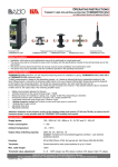
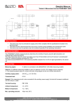
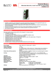
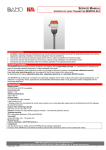
OPERATING INSTRUCTIONS TURBIDITY LIMIT-VALUE EVALUATION UNIT TURBISWITCH GS4 WITH MEASURING SENSOR OR IMMERSION PROBE Evaluation Unit TURBISWITCH GS4 Measuring Sensor (for installation in piping) TURBISWITCH GA1 TURBISWITCH GA5 TURBISWITCH GA11 Immersion Probe TURBISWITCH CP2 Safety Precautions: Installation, initial start-up and maintenance may only be performed by trained personnel! The device may only be connected to power which complies with the specifications included in the technical data and on the serial plate! The device must be disconnected from all sources of power during installation and maintenance work! The device may only be operated under the conditions specified in the operating instructions! Functions Description: TURBISWITCH GS4 evaluation unit with required measuring sensor for installation in piping, TURBISWITCH GA1, GA5, GA11 or TURBISWITCH CP2 immersion probe Turbidity measurement is based on the absorption process, i.e. it reacts to reduced light due to suspended sediment in the liquid. Measurement is insensitive to extraneous light thanks to the use of pulsed infrared light. Measuring sensitivity depends on the length of the measuring section. The shorter the measuring section, the more turbid the liquid can be. Pulsed infrared light is transmitted from the emitter through the liquid to the receiver. If the selected turbidity value is exceeded or fallen short of, the output relay in the switching amplifier reacts. Digital communication between the devices Turbidity dynamics for the overall sensing range: >100dB Measuring sensor for installation in piping: max. roughly 10,000 FAU (depending on diameter) Immersion probe for open containers or troughs: max. roughly 30,000 FAU 3 adjustable measured value ranges (low / medium / high) 1 floating changeover contact (both contacts are open when supply power is switched off) 1 floating alarm output contact Adjustable delay time Adjustable hysteresis Attention! Operation of the previous version of the turbidity emitter and receiver (TT-GS and TR-GS), as well as the CP1 immersion probe, is only possible with the TRUBOMAT GS3 turbidity limit monitor. Technical Data: Supply power: 100 - 255V AC / 50 - 60Hz or 10 - 3V DC and 12 - 24V AC Power consumption: 1 - 5W Ambient temperature: -10…+45°C Output relay switching capacity: 250V AC, 3A / 30V DC, 1A Caution: Contacts are not protected against overload – use external protective device! Housing: 22.5x100x122mm, IP40, for top-hat rail: 35x7.5mm (DIN EN 50 022) Terminals: Screw terminal for wire cross-sections of up to 1.5mm² Threshold value adjustment: 3 x 0 - 100% range, low (5% steps), medium (2% steps), high (1% steps) BAMO IER GmbH Pirnaer Str. 24 D-68309 Mannheim, Germany Phone: +49 (0)621 84224-0 Fax: +49 (0)621 84224-90, e-mail: [email protected] Internet: www.IER.de SU3547a.doc 10/12 1 OPERATING INSTRUCTIONS TURBIDITY LIMIT-VALUE EVALUATION UNIT TURBISWITCH GS4 WITH MEASURING SENSOR OR IMMERSION PROBE Technical Data (continued): Reset hysteresis: Adjustable from 1 to 25% Sensor power supply: 15V DC, max. 100mA Display: Threshold value: Switching status: Range display: Adjustment: Rotary knob / pushbutton on front panel 2½-place LED, 5 x 7 pixel matrix display 1 blue LED = limit value exceeded 3 yellow LEDs = low / medium / high CE Mark: In accordance with low-voltage directive (2006/95/EC) and EMC directive (89/336/ECC) Controls – Rotary Knob / Pushbutton: Turn: The threshold value is adjusted at menu level 0. Hysteresis and time delay are selected at menu level 1. The desired numeric value is selected at menu level 2 (clockwise = + and anticlockwise = –). Press: Used to select submenus 1 and 2. Pushing the button in submenu 2 returns the display to menu 1. Note: If none of the controls are activated for 10 seconds, the device is automatically returned to menu 0. Possible Displays: Threshold value of 0 - 100% in the respective setting range (low / medium / high). TR: receiver error or receiver not connected TT: emitter error or emitter not connected In the case of correct, internal measured value processing, the LEDs on the emitter and the receiver must always blink (continuous illumination = error). Threshold Value Relay: Blue LED lights up = threshold has been exceeded Limit Value: 100% high 100% med 100% low 0% low/med/high Setting range: 3 x 0 to 100% Note: Switching to the next higher or lower measuring range is accomplished automatically by simply continuing to turn the adjusting knob. 100% in the low range is followed by 0% in the medium range. 100% in the medium range is followed by 0% in the high range. 100% in the high range is the highest possible threshold value. One yellow LED lights up in the low range. Two yellow LEDs light up in the medium range. Three yellow LEDs light up in the high range. whole detecting range Delay Time: Setting range of 0.1 to 9.9 s above/below the selected limit value wait for delay time to elapse the relay is then switched Default setting: 0.1 s BAMO IER GmbH Pirnaer Str. 24 D-68309 Mannheim, Germany Phone: +49 (0)621 84224-0 Fax: +49 (0)621 84224-90, e-mail: [email protected] Internet: www.IER.de SU3547a.doc 10/12 2 OPERATING INSTRUCTIONS TURBIDITY LIMIT-VALUE EVALUATION UNIT TURBISWITCH GS4 WITH MEASURING SENSOR OR IMMERSION PROBE Hysteresis: Setting range: 1 - 25%. The output relay is not switched back until the measured value is fallen short of by the selected percentage value. Default setting: 1% Fault Contact: This contact is normally closed. The contact is opened in the case of an error at the emitter or receiver. The type of error appears at the display (TR = receiver error, TT = emitter error). Reset to Default Values: Switch supply power on. Within 3 seconds (i.e. during the test routine), press and hold the pushbutton for approximately 5 seconds: The display counts up: 1, 2, 3, 4 ... 99, ST ... All settings are returned to their default values. Switching Supply Power On: After supply power has been switched on, the device starts a test routine during which all LEDs and the digital display are activated (lamp test). After about 1 second, the software version is briefly displayed. The display is then switched to menu level 0 (threshold value display). Block Schematic: Turbiswitch GS4 Emitter+ Power supply 100 - 250V AC or 10 - 30V DC Power supplyl galvanically isolated Receiver+ Immersion proberLimit-value passed Display Failrue TX RX Receiver100 Ohm Signal processing 100 Ohm Limit-value underrunned Signal Immersion probe Operating Menu: Low Threshold Value 0 Medium Threshold Value 0-100 High Threshold Value 0-100 Hysteresis Selection Time Delay Selection Hysteresis: 1 to 25% Delay: 0.1 to 9. 9s 1 Turn knob 2 Press button Back to level 1 LED off LED on Back to level 1 BAMO IER GmbH Pirnaer Str. 24 D-68309 Mannheim, Germany Phone: +49 (0)621 84224-0 Fax: +49 (0)621 84224-90, e-mail: [email protected] Internet: www.IER.de SU3547a.doc 10/12 3 OPERATING INSTRUCTIONS TURBIDITY LIMIT-VALUE EVALUATION UNIT TURBISWITCH GS4 WITH MEASURING SENSOR OR IMMERSION PROBE Installation and Connection of the Measuring Sensor in Piping: Achievable turbidity values depend to a great extent on the utilised medium and the length of the measuring section. The length of the measuring section results from the pipe diameter. Minimum acquirable turbidity in the low range begins at roughly 50 to 100 FAU. Maximum acquirable turbidity in the high range: Maximum acquirable turbidity in the medium range: Maximum acquirable turbidity in the low range: Approx. 3000 to 10,000 FAU i.e. roughly 10 to 30 g/l SiO2 10% of the high range 1% of the high range Mechanical installation: Installation of TURBISWITCH GA1, GA5 and GA11 measuring sensors in piping. The measuring sensors can be installed to main lines as well as branch lines. Direction of flow Horizontal mounting (top view) Emitter Direction of flow Receiver Emitter Emitter Bypass mounting (top view) Emitter Direction of flow Receiver Receiverr Direction of flow Direction of flow Emitter Receiver Vertical mounting Mounting with odour trap The following must be observed in order to assure reliable measurement: Lenses must always be kept clean. Cleaning intervals depend on operating conditions. Always align the emitter and the receiver horizontally. R E R E The measuring sensor must always be filled during measurement. If the system comes to a standstill, liquid should remain in the measuring sensor in order to prevent residue in the liquid from becoming caked onto the lenses. It may be advisable to provide for back pressure by means of restriction, or to install a trap. The liquid to be measured must be free of gas bubbles. Gas bubbles distort measurement results. Installation of a trap is advantageous. It’s advisable to include stabilizing zones upstream and downstream from the measuring sensor of at least 3 to 5 times the diameter of the piping. If a trap is installed, include a drain cock so that no liquid escapes when the lenses are removed. Use the included assembly set in order to remove the lenses from measuring sensors GA5 and GA11 (key and suction cup). BAMO IER GmbH Pirnaer Str. 24 D-68309 Mannheim, Germany Phone: +49 (0)621 84224-0 Fax: +49 (0)621 84224-90, e-mail: [email protected] Internet: www.IER.de SU3547a.doc 10/12 4 OPERATING INSTRUCTIONS TURBIDITY LIMIT-VALUE EVALUATION UNIT TURBISWITCH GS4 WITH MEASURING SENSOR OR IMMERSION PROBE Installation and Connection of the Measuring Sensor in Piping (continued): The side with the dot has an anti-contamination coating. Install this end towards the medium! Observe in case of lenses with anti-contamination coating! Glass Armature Compression piece O-Ring Emitter / Receiver Electrical Connection Receiver Emitter 10-30V DC 100-255V AC L N IR light TT-HDR Emitter TR-HDR Receiver Fuse 16 14 8 2 6 1 3 4 Power supply Switching logic OC V+ RX 11 9 12 Failure Limit-value << Limit-value >> Turbiswitch GS4 13 V+ Limit-value Limit-value no underrunned passed failure failure 13 15 13 15 11 9 12 11 9 12 15 Signaling and Controlling equipment Attention! All relays contacts are open when supply power is switched off. BAMO IER GmbH Pirnaer Str. 24 D-68309 Mannheim, Germany Phone: +49 (0)621 84224-0 Fax: +49 (0)621 84224-90, e-mail: [email protected] Internet: www.IER.de SU3547a.doc 10/12 5 OPERATING INSTRUCTIONS TURBIDITY LIMIT-VALUE EVALUATION UNIT TURBISWITCH GS4 WITH MEASURING SENSOR OR IMMERSION PROBE Installing and Connecting the Immersion Probe: The following measuring ranges apply when the TURBISWITCH CP2 immersion probe is used: Minimum acquirable turbidity in the low range begins at roughly 100 to 300 FAU. Maximum acquirable turbidity in the high range: Approx. 30,000 FAU i.e. roughly 100 g/l SiO2 Maximum acquirable turbidity in the medium range: 10% of the high range Maximum acquirable turbidity in the low range: 1% of the high range Installing the immersion probe: The TURBISWITCH CP2 immersion probe is intended for installation into slurry tanks, open troughs and containers for monitoring turbidity, or as a sludge level indicator. Install the probe so that it can be easily removed for cleaning. Cleaning intervals depend on operating conditions. Do not scratch the lenses while cleaning! Installing the TURBISWITCH CP2 ZK/Z0 immersion probe: Z0: Shipped without installation materials. ZK: Install using the included mounting bracket and adjuster fitting. Attention: In the case of powerful flow or viscous media, the cable may not be overstretched. If this is the case, a strain relief must be secured to the two holes in the base of the probe (cord, retaining rod or the like). The holes are laid out so that M6 threads can be cut into them if required. Installing the TURBISWITCH CP2 ZR immersion probe: For permanent installation to tanks or basins, the CP2 immersion probe is available with a probe tube which can be screwed off. Electrical connection: 10-30V DC 100-255V AC L N Shield (supply-) white (Signal) Fuse brown (supply+) 16 14 8 2 6 1 3 4 Power supply Switching logic RX OC V+ V+ Failure Limit-value << Limit-value >> Turbiswitch GS4 Limit-value Limit-value no underrunned passed failure failure 13 15 13 15 Immersion probe CP2-HDR 11 11 9 12 13 Signaling and controlling equipment 9 12 11 9 12 15 Attention! All relays contacts are open when supply power is switched off. BAMO IER GmbH Pirnaer Str. 24 D-68309 Mannheim, Germany Phone: +49 (0)621 84224-0 Fax: +49 (0)621 84224-90, e-mail: [email protected] Internet: www.IER.de SU3547a.doc 10/12 6 OPERATING INSTRUCTIONS TURBIDITY LIMIT-VALUE EVALUATION UNIT TURBISWITCH GS4 WITH MEASURING SENSOR OR IMMERSION PROBE Initial Start-Up, Adjusting the Switching Point: Adjustment takes place after installation and electrical connection. Set to smallest possible values in the hysteresis and time delay menus (1% and 1 s). Wait 15 seconds until menu level 0 is displayed. Turn the rotary knob clockwise to 100% in the high range. The blue LED does not light up. Fill the measuring sensor with liquid or submerge the immersion fitting. Slowly turn the rotary knob anticlockwise towards 0% until the blue LED lights up (current turbidity value). If the switching point is below 10% in the high range, continue turning anticlockwise into the medium range in order to allow for more accurate adjustment. If the switching point is below 10% in the medium range, continue turning anticlockwise into the low range in order to allow for more accurate adjustment. Then adjust down a few more percentage steps from the current switching point. The closer the value is to the switching point, the more sensitively the device reacts to increasing turbidity. If a larger change is desired, the value must be set correspondingly higher (empirical value). In order to prevent erroneous switching due to air bubbles or isolated turbidity particles, the switching command can be delayed by adjusting delay time (TD) to a value of up to 9.9 seconds. A fluttering switching point can be avoided by increasing reset hysteresis (HY). Troubleshooting during Initial Start-Up Error Blue LED does not go out. “TT” appears at the display. Cause Turbidity in the measuring section is greater than the sensing range. Emitter error, emitter not connected, emitter not visible to the receiver “TR” appears at the display. Incorrect switching point Receiver error or receiver not connected Deposits on lenses Fill-level too low Incorrect turbidity range has been selected Remedy Inspect the measuring section and remove obstacles or clean the lenses. Check emitter connection, inspect the measuring section and remove obstacles or clean the lenses. Check receiver connection. Clean the lenses. Fill up the measuring sensor. Change the turbidity range. Maintenance: Measuring sensor: If contaminated, the lenses have to be cleaned. A suction cup is included with the TURBISWITCH GA5 and GA11 measuring sensors to this end. Armature Glass Compression piece O-Ring Emitter / Receiver The side with the dot has an anti-contamination coating. Install this end towards the medium! Fully drain the measuring sensor before performing any maintenance or cleaning work!!! Do not use any hard objects for cleaning. Calcium deposits can be removed with commercially available decalcifiers. Maintenance intervals depend on operating conditions. BAMO IER GmbH Pirnaer Str. 24 D-68309 Mannheim, Germany Phone: +49 (0)621 84224-0 Fax: +49 (0)621 84224-90, e-mail: [email protected] Internet: www.IER.de SU3547a.doc 10/12 7