1
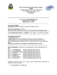
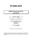
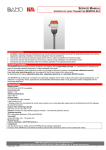
OWNERS MANUAL TURBIDITY MEASURING SYSTEM TRUBOMAT GAB Safety Precautions: The device may only be connected to supply power which complies with the specifications included in the technical data! The device must be disconnected from all sources of power during installation and maintenance work! The device may only be operated under the conditions specified in the operating instructions! Functions Description: The TRUBOMAT turbidity measuring device determines the turbidity of liquids using the light absorption and scattered light measuring method. The inline measuring cell at the sensor set makes use of two IR transmitters and one IR receiver in pulsating light mode (IR measuring method according ISO 7027). The interconnected BAMOPHOX TUR measuring amplifier analyses the 4 to 20 mA signal generated by the sensor set. Technical Data: Measuring signal: 4- 20mA, for connection to the BAMOPHOX TUR (436) measuring amplifier Observe: If a different measuring amplifier is used, an external 10 to 30 V DC voltage source is required. The measuring signal output is a current sink (see wiring diagram at the end of these instructions). Auxiliary supply power: 24V DCrated (10- 30V DC) Connected load: 0.5 W Remark: If the measuring circuit is also connected to the auxiliary power supply, the load will increase to additional 24V DCx 20mA= 0,48W Terminal housing: PBT, IP65 Ambient temperature: +5...+45°C Medium temperature: +5...+ 60°C Max. operating pressure: 10bar max. 60°C BAMO IER GmbH Pirnaer Straße 24 D-68309 Mannheim Tel. +49 (0)621 84224-0 Fax: +49 (0)621 84224-90 www.bamo.de [email protected] SU3334b.doc 11/13 1 OWNERS MANUAL TURBIDITY MEASURING SYSTEM TRUBOMAT GAB Technical Data (continuation): Measuring range: Version 20: 0,01- 20FNU Version 1000: 0,1- 1000FNU (5 selectable resolutions) FNU= “Formazine Nephelometric Units“ Measuring accuracy: ±5% of actual measuring value, ±1% of upper limit of effective range Colour- / Fouling compensation: only for GAB 20 available Control elements: 6-fold DIP switch calibration potentiometer Indicators: Status LED (green) Fault LED (red) CE-Marks: In accordance with low-voltage directive (RL 2006/95/EWG) and EMC-directive (2004/108/EWG) BAMO IER GmbH Pirnaer Straße 24 68309 Mannheim Tel. +49 (0)621 84224-0 Fax: +49 (0)621 84224-90 . www.bamo.de [email protected] SU3334b.doc 11/13 2 OWNERS MANUAL TURBIDITY MEASURING SYSTEM TRUBOMAT GAB Installing the Sensor Fixture: Observe: The fixture must be installed vertically! Best installation is the mounting in a ascending tube with slow down section 600 mm in front and 400 mm behind the turbidity measuring device The sensor fixture must be completely filled with liquid medium during the performance of measurements. Install to the vertical portion of a siphon trap if necessary. Air bubbles distort measurement results. Glasses must be clean – clean at regular intervals as required. The sensor set consists of a receiver module with microprocessor-controlled analysis electronics and two transmitter modules. The sensor set generates a 4 to 20 mA output signal in accordance with the following diagram. Measuring ranges are selected with the help of the DIP switches on the receiver module. TRUBOMAT GAB 20 DIP Switch Settings DIP1 DIP2 Measuring Range [FNU] 1 = 0,01 ... 2 = 0,01 ... 3 = 0,01 ... 4 = 0,01 ... 5 = 0,01 ... 1 2 5 10 20 ON OFF ON OFF ON ON OFF OFF ON ON DIP3 OFF ON ON ON ON DIP4 OFF OFF OFF OFF OFF TRUBOMAT GAB 1000 DIP5 OFF OFF OFF OFF OFF DIP6 *) OFF OFF OFF OFF OFF *) DIP 6= ON Colour-/ Fouling compensation is switched on DIP Switch Settings DIP1 Measuring Range DIP2 DIP3 DIP4 DIP5*) DIP6*) OFF ON OFF ON OFF OFF OFF ON ON OFF OFF OFF OFF OFF OFF ON ON ON ON OFF OFF OFF OFF OFF OFF OFF OFF OFF OFF OFF [FNU] 1 = 0,1 ... 50 2 = 0,1 ... 100 3 = 0,1 ... 200 4 = 0,1 ... 500 (**300) 5 = 100 ...1000 *) DIP-switch 5 and 6 without function, Normal position= OFF **) armatures with nominal diameter > DN65 - DN100 Troubleshooting: Measuring current 22 mA = overflow Measuring current 0 mA = wrong DIP-switch setting (no valid measuring range selected) Indication green LED= 1Hz blinking green LED= permanent ON green LED= OFF Fault indication red LED= ON red LED= 1Hz blinking only TURBICUBE 20 ready, measuring in operation ready, measuring not in operation no power supply or defective = measuring circuit faulty, (short circuit or broken) = glasses dirty or liquids to much colorized (damping factor> 20dB) BAMO IER GmbH Pirnaer Straße 24 68309 Mannheim Tel. +49 (0)621 84224-0 Fax: +49 (0)621 84224-90 . www.bamo.de [email protected] SU3334b.doc 11/13 3 OWNERS MANUAL TURBIDITY MEASURING SYSTEM TRUBOMAT GAB Installing the Sensor Fixture (continuation): Note: The turbidity measuring instruments are calibrated with the internationally specified standard suspension Formazin. The indication takes place thus not in form of the measured light intensity, but as concentration of the Formazin calibration suspension. During the measurement of any liquid this means thus that the liquid concerned causes the same light scattering as the standard suspension of the indicated concentration. Measured values of other turbidity measuring instruments, which use other calibration suspensions and measuring angle, cannot be compared directly with those with Formazin calibrated measuring instruments! Receiver Module PCB DIP-switch calibration potentiometers (number of potentiometers depends on type) terminals Electrical Connection: m a x . b u r de n i n m e a su r i n g c i r c u i t 1200 1000 800 600 400 200 0 10 15 20 25 30 v ol t a ge ( V ) Observe: The measuring output “4- 20 mA" is a current drain, that means, the output channel has the same electrical behavior as a variable resistor. A active power supply for the measuring circuit is always needed. Connection to BAMOPHOX TUR (463) see Operation instruction SU0325 BAMO IER GmbH Pirnaer Straße 24 68309 Mannheim Tel. +49 (0)621 84224-0 Fax: +49 (0)621 84224-90 . www.bamo.de [email protected] SU3334b.doc 11/13 4 OWNERS MANUAL TURBIDITY MEASURING SYSTEM TRUBOMAT GAB Maintenance: Cleaning intervals depend upon the type of liquid medium and must be determined by the user. Cleaning the lenses: Disconnect the turbidity-measuring instrument from all sources of power. Depressurize pipes and empty liquid medium from the device. Remove the transmitters and the receiver from the fixture by unscrewing the sleeve nuts. Unscrew the compression Remove the O-ring. disc with the included tool and remove. Remove the lens with the included suction cup. and clean the lens – do not use abrasive cleansers, which may cause scratching!! Reassemble after cleaning by following the above instructions in reverse. Note: Inspect the O-ring before reassembly and replace if necessary. tighten the compression disc with the included tool (use the rod of the suction cup as a lever). Before reinstalling the transmitters and the receiver, refill the fixture with liquid medium and inspect for possible leaks. Mounting This side has a dirt repellent coating. This side must face the medium after the lens has been mounted! Observe the point Observe positioning of hole and pin! Observe above note if coated lenses are used! Observe for cold fluids The fixture has to be installed to the pipelines with mounted sensors only For cleaning the glasses dismount the complete fixture, after cleaning install as described above BAMO IER GmbH Pirnaer Straße 24 68309 Mannheim Tel. +49 (0)621 84224-0 Fax: +49 (0)621 84224-90 . www.bamo.de [email protected] SU3334b.doc 11/13 5 OWNERS MANUAL TURBIDITY MEASURING SYSTEM TRUBOMAT GAB Testing and Readjustment: Factory Calibration The sensor set is equipped with a calibration constant as a design feature. As a rule, no recalibration is required. Calibration point accuracy is better than 2%‚ and drift is less than 1% per year. Test Equipment Monitoring If device calibration testing is required as part of the respective quality assurance system for test equipment monitoring, calibration can be checked with the calibration rods, and the device can be readjusted if necessary. A suitable calibration standard is delivered with each turbidity measuring instrument. Each calibration standard is matched to the specific circumstances of the mating turbidity measuring instrument, and cannot be used for other measuring instruments of the same type! The calibration standard and the turbidity measuring instrument must have the same serial number! Calibration box with mounting tool and calibration rod for TURBICUBE 20 (for TURBICUBE 1000 there are two rods in the box) BAMO IER GmbH Pirnaer Straße 24 68309 Mannheim Tel. +49 (0)621 84224-0 Fax: +49 (0)621 84224-90 . www.bamo.de [email protected] SU3334b.doc 11/13 6 OWNERS MANUAL TURBIDITY MEASURING SYSTEM TRUBOMAT GAB Testing and Readjustment (continuation): Attention: It must be assured that all utilised control and switching devices are switched off during recalibration! Procedure for TRUBOMAT GAB 20: The following adjustment sequence must be adhered to!! Clean all lenses and wipe them dry (all visible water droplets and water film must be removed!). Then reinstall the lenses for the receiver and the S1 transmitter only. Do not yet install the lens and the compression disc for the S2 transmitter (180° scattered light)!! Reinstall the S1 transmitter and the receiver. Remove the KN 20 calibration rod from the box. Insert the calibration rod into the fixture Mount the S2 transmitter to the calibration rod (observe the locking pin) Insert the calibration rod with attached transmitter completely into the fixture (observe the locking pin), and tighten the sleeve nut. Set the DIP switches to the MB5 range = 0,01 to 20NTU (ON/ON/ON/OFF/OFF/OFF) Switch supply power back on again – the status LED blinks! Compare the setpoint value and the actual value. Setpoint 1 (SW1) = setpoint on the plate in the box of the KN20 calibration rod Actual value = measured value Setpoint / actual value deviation: Less than ±5% measuring instrument is OK Greater than ±5% adjust actual value with potentiometer P4 remove transmitter and calibration rod mount glass with sealing ring and compression disc and transmitter S2 mount glass with sealing ring and compression disc and transmitter S2 select the right DIP-switch setting for operation BAMO IER GmbH Pirnaer Straße 24 68309 Mannheim Tel. +49 (0)621 84224-0 Fax: +49 (0)621 84224-90 . www.bamo.de [email protected] SU3334b.doc 11/13 7 OWNERS MANUAL TURBIDITY MEASURING SYSTEM TRUBOMAT GAB Testing and Readjustment (continuation): Procedure for TRUBOMAT GAB 1000: The following adjustment sequence must be adhered to!! Step 1 Clean all lenses and wipe them dry (all visible water droplets and water film must be removed!). Then reinstall the lenses for the receiver and the S1 transmitter only. Do not yet install the lens and the compression disc for the S2 transmitter (180° scattered light)!! Reinstall the S1 transmitter and the receiver. Remove the KN-D calibration rod (through light) from the box. Insert the calibration rod into the fixture Mount the S2 transmitter to the calibration rod (observe the locking pin) Step 2 Insert the calibration rod with attached transmitter completely into the fixture (observe the locking pin), and tighten the sleeve nut. Set the DIP switches to the MB5 range = 100 to 1000 (all DIP-switches OFF). Switch supply power back on again – the status LED blinks! Compare the setpoint value and the actual value. Setpoint 1 (SW1) = setpoint on the plate in the box of the KN-D calibration rod Actual value = measured value Setpoint / actual value deviation: Less than ±5% measuring instrument is OK Greater than ±5% adjust actual value with potentiometer P3 Remove the KN-D calibration rod (through light). Remove the KN-S calibration rod (scattered light) from the box. Mount the calibration rod to the S2 transmitter as described above. DIP switches stay on the MB5 range = 100 to 1000 (all switches off). Compare the setpoint value and the actual value. Setpoint 2 (SW2) = setpoint on the plate in the box of the KN-S calibration rod Actual value = measured value Setpoint / actual value deviation: Less than ±5% measuring instrument is OK Greater than ±5% adjust actual value with potentiometer P2 Step 3 Set the DIP switches to the MB4 range = 0,1 to 500 (DIP-switches ON/ON/OFF/ON/OFF/OFF). Compare the setpoint value and the actual value. Setpoint 3 (SW3) = setpoint on the plate in the box of the KN-D calibration rod Actual value = measured value Setpoint / actual value deviation: Less than ±5% measuring instrument is OK Greater than ±5% adjust actual value with potentiometer P4 Remove the KN-D calibration rod. Step 4 mount glass with sealing ring and compression disc and transmitter S2 select the right DIP-switch setting for operation BAMO IER GmbH Pirnaer Straße 24 68309 Mannheim Tel. +49 (0)621 84224-0 Fax: +49 (0)621 84224-90 . www.bamo.de [email protected] SU3334b.doc 11/13 8 OWNERS MANUAL TURBIDITY MEASURING SYSTEM TRUBOMAT GAB Dimensions: Dimension drawing GAB RG __7 (DN 65 round thread) Type GAB FF __3 GAB FF __4 GAB FF __5 GAB FF __6 GAB FF __7 GAB FF __8 GAB FF __9 Nominal diameter DN25 DN32 DN40 DN50 DN65 DN80 DN100 GAB RG __3 GAB RG __4 GAB RG __5 GAB RG __6 GAB RG __7 GAB RG __8 GAB RG __9 DN25 DN32 DN40 DN50 DN65 DN80 DN100 Process connection both sides flange DIN 2633 PN10 both sides flange DIN 2633 PN10 both sides flange DIN 2633 PN10 both sides flange DIN 2633 PN10 both sides flange DIN 2633 PN10 both sides flange DIN 2633 PN10 both sides flange DIN 2633 PN10 both sides round thread RG DIN 11851 SKC both sides round thread RG DIN 11851 SKC both sides round thread RG DIN 11851 SKC both sides round thread RG DIN 11851 SKC both sides round thread RG DIN 11851 SKC both sides round thread RG DIN 11851 SKC both sides round thread RG DIN 11851 SKC Inner diameter mounting distance X meas. tube (1 mm) DN65 274 DN65 252 DN65 230 DN65 190 DN65 233 DN100 208 DN100 240 DN65 DN65 DN65 DN65 DN65 DN100 DN100 288 266 244 202 249 218 260 BAMO IER GmbH Pirnaer Straße 24 68309 Mannheim Tel. +49 (0)621 84224-0 Fax: +49 (0)621 84224-90 . www.bamo.de [email protected] SU3334b.doc 11/13 9