1
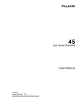
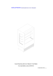
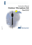
Operating Instructions
1.3
as long as loop B is occupied. Not until loop B
has been completely vacated, does the output
signal decline again.
AB PRESENCE MODE
Loop
A
B
RLY A
RLY B
The same principle applies correspondingly on
driving onto the loops from the other direction.
no
no
yes
no
yes
no
no
no
In the "AB PRESENCE MODE" a directiondependent signal is issued which can be used if
the presence of a vehicle on loop B is to be
signalled.
Cases for application can be, for example,
parking barriers or gates with an automatic
timer function which should not be allowed to
close until a vehicle has completely left the
closing area (loop B).
Principle:
If a movement from loop A to loop B takes
place, then only output A in accordance with
the diagram is switched. After loop A has been
activated, output A remains switched
The relay output jumpers PP1and PP2 cannot
be adjusted in this operating mode but are
permanently switched to continuous operation
(PRESENCE).
Cleaning
•
•
Carefully wipe down the casing with a
damp, lint-free cloth.
Do not use any cleaning agents containing
solvents. These pose a health risk and can
damage the casing surface.
Disposal
Waste electrical products and batteries may
not be disposed of with household waste!
Dispose of the waste product via
a collection point for electronic
scrap or via your specialist
dealer.
Put the packaging material into a
container for cardboard and
paper.
Induction Loop Detector
Technical Data
Frequency range
Inductance range
Sensitivity
Response time
Power supply
Current input
Output
Max. contact rating
Temperature range
Dimensions
Weight
7
ILD21
ILD22
4-stage adjustable: 20 – 140 kHz
20 – 1.500 µH
4-stage adjustable
approx. 120 ms
230 V AC ± 15 %; 12-24 V AC / DC ± 15 %
165 mA
2 relays
5 A / 230 V AC
-40 °C to +80 °C
75 x 40 x 76 (90 incl. connector) mm (H x W x D)
approx. 220 g
69178 0608 GB
230 V AC
12 - 24 V AC/DC
Operating Instructions
Operating Instructions
Fig. 1 (unit front)
Operating Instructions
Fig. 2 (PCB, inside)
Important:
To adjust the jumpers, remove the casing
cover. Any adjustments must always be
made in the de-energized state.
In the continuous operating mode
(PRESENCE), the output remains switched as
long as a vehicle is located within the loop's
range of action. With pulse operation (PULSE)
the output relay switches for approx. 0.8 s once
the loop has responded.
1.
1.2
AB Logic Direction Detector
Jumper AB (see fig. 2)
AB PULSE MODE
Loop
A
*ex factory state
1.1
Fig. 3 (Connection scheme, see also side of casing)
AB OFF
Loop
A
B
RLY A
RLY B
yes
no
yes
no
no
yes
In the "AB OFF" mode both loops are operated
independent of each other.
In the "AB OFF" mode, the relay output of each
loop (jumper PP1 or PP2) can be set for either
pulse operation (PULSE) or continuous
operation (PRESENCE):
B
RLY A
RLY B
no
no
no
no
yes (pulse)
no
In the "AB PULSE MODE“ a directiondependent signal is issued which can be used
if the departure of a vehicle from the triggering
loop is to be signalled.
Cases for application can be, for example,
parking barriers or gates which should not
receive a command to close until a vehicle has
completely left the closing area (loop A).
Principle:
If a movement from loop A to loop B takes
place, then only output A in accordance with
the diagram is switched. Output A generates a
pulse if on vacating loop A, loop B is still
occupied.
The same principle applies correspondingly
when the loops are driven onto from the other
direction.
The relay output jumpers PP1and PP2 cannot
be adjusted in this operating mode but are
permanently switched to pulse operation
(PULSE).
*ex factory state
CONNECT THE CORRECT SUPPLY VOLTAGE !
ILD21 CONNECTIONS 1, 2 (N, L)
230 V AC,
ILD22 CONNECTIONS 1, 2 (N, L)
12 - 24 V AC/DC
1
69178 0608 GB
69178 0608 GB
6
Operating Instructions
SENS Setting the Sensitivity
The sensitivity can be set for various vehicle
types:
The settings "MED-HIGH" or "MED-LOW" are
optimized for the majority of applications. For
vehicles with minimal metal mass (e.g.
bicycles), the sensitivity can be set at HIGH.
Operating Instructions
Switch 7: ASB
Example: signal sequence for long truck
combinations with and without ASB:
Loop
A or B
Description of Function
ILD Induction Loop Detector,
Operating Instructions
Together with the wire loops laid in the
ground, the induction loop detectors are
designed for detecting vehicles (metal
masses) and triggering an action.
Accessories: Connecting base "ILD-RELBASE“
Signal
Switches 3, 4: sensitivity channel 1
Switches 5, 6: sensitivity channel 2
Supply package, Accessories
no
Safety Advice
•
yes
•
yes (with ASB)
no (without ASB)
yes
no
Change in inductance ∆L/L in the case of
various vehicle types (loop 2m x 1m,
3 windings):
Bicycle
0.02%
Motorcycle
0.12%
Truck
0.4%
Car
>1.0%
ASB Automatic Sensitivity Boost
If the ASB is switched on, when a vehicle is
detected the sensitivity of the detector is
automatically increased to the maximum. In this
way long truck combinations and vehicles with
high-set chassis can be reliably identified and
premature closing, e.g. of a barrier, prevented.
5
Switch 8: PRES
Electrical installation and programming
may only be carried out by a qualified
electrician!
•
Have faulty units checked by the
manufacturer!
•
Do not make any unauthorized alterations
or modifications to the unit!
PRES Signal Holding Time
The signal holding time can be set via switch
8 for either PERMANENT PRESENCE or
LIMITED PRESENCE.
Before connecting and putting the unit
into operation, carefully read through
the Operating Instructions.
Designated Use
•
They can be used for controlling parking lot
barriers, warehouse rolling shutters, garage
doors or also for detecting vehicles in front of
automatic traffic lights.
The 2-channel models can also detect the
direction in which vehicles are travelling.
Special Features:
•
Automatic self-adjustment on the loop
connected as well as after altering the
unit's settings. This guarantees that the
unit is easy to put into service and to
operate.
•
Maintenance-free thanks to automatic
compensation of atmospheric and
environmental influences.
•
Adjustable sensitivity and automatic
sensitivity boost to reliably identify various
vehicle types.
•
Output via floating relay contacts with a
max. contact rating of 5 A / 230 V AC.
•
Indication of operating state and
malfunctions via LEDs.
The unit may only be used as a
decoder device for induction loops!
Unpacking
At the "PERMANENT PRESENCE" setting,
the detector will constantly compensate for all
atmospheric and environmental influences as
long as a vehicle occupies the loop.
At the "LIMITED PRESENCE" setting, the
detector will constantly compensate for all
atmospheric and environmental influences for
the duration of approx. 45 minutes, after
which the output is automatically reset.
69178 0608 GB
Unpack the items supplied. Check that the
delivery is complete!
Dispose of the packaging in the
designated collection containers for the
recycling of cardboard, paper and plastic.
69178 0608 GB
2
Operating Instructions
Operating Instructions
Functional Restrictions
•
"Cross-talk"
If the loops of two detectors are located directly
next to each other, then the magnetic fields can
overlap and cause interference, resulting in
malfunctions. This can be avoided by taking the
following measures:
•
•
•
•
Set different working frequencies on the
detectors. The closer the loops are to
each other, the greater the difference in
frequency should be.
Increase the distance between the two
loops ( > 2 meters recommended).
If the feeder cable is laid next to other
electric cables, it should be shielded. This
shielding only needs to be earthed on the
detector side.
The feeder cable must be twisted with
approx. 20 turns per meter.
The sensitivity of the loop reduces, the
longer the feeder cable is. The feeder
cable should therefore be as short as
possible and not exceed 100 meters in
length.
•
"Feeder cable and loop cable"
•
The feeder cable and loop cable should
be of the same material. Junction points
between the loop and feeder cable should
be avoided.
•
The cable must be of the insulated wire
2
type with a cross-section of >1.5 mm
(recommended: loop cable type SIAF
1.5 mm²).
3
Make sure that the induction loops are not
occupied while self-adjustment is taking
place since also the sensitivity of the loop
is redetermined during this process.
FREQ Setting the Frequency
Putting into Operation
Connect the induction loops, the relay outputs
and the supply voltage. Please note:
ILD21 connections 1, 2
230 V AC
ILD22 connections 1, 2
12 - 24 V AC/DC
"Detector"
•
Attach the detector in a suitable weatherprotected location.
Given the size of loop stated below, the
following number of windings are required:
Size of loop
3- 6m
6 - 10 m
10 - 30 m
•
Number of windings
4
3
2
Place the loops in the grooves which must
be cut into the road surface (fig. 5). To
accommodate the feeder cable, a groove
should be run from one corner of the loop
to the corner of the road.
Nominal groove width:
Nominal groove depth:
Important:
Each time the settings on the unit have
been altered, the RESET button must be
pressed!
The unit then automatically performs a selfadjustment!
Fig. 4
•
Settings and Adjustments
Fig. 5
The length of the loop is determined by
the width of the road to be monitored. It
should extend up to 300 mm from each
edge of the road (fig. 4).
Add two more windings to the loop.
Select the maximum distance possible
between the steel reinforcement and the
loop cable.
Installation Instructions
•
The loop corners should be set at an
angle of 45° in order to avoid damaging
the cable (fig. 4).
Twist the feeder cable to the detector
(> 20 turns per meter).
Installing the Induction Loop
"Reinforcements"
Steel reinforcements under the road can
adversely affect the performance of the loop
detection system. This interference can be
reduced by taking the following measures:
•
•
•
4 mm
30 – 50 mm
69178 0608 GB
After being switched on for the first time, as
well as following a power failure or after every
RESET, the detector automatically performs a
self-adjustment (depending on the set
frequency "FREQ", the LED’s CH1 and CH2
flash 4 to 7 times).
After the automatic self-adjustment has been
completed, the ON LED lights up. The unit is
now ready for operation.
If, for example, two detectors are installed, the
risk of cross-talk beween adjacent induction
loops can be avoided by setting different
working frequencies on the detectors (see also
"cross-talk" in the section "Functional
Restrictions").
Switches 1, 2: setting the frequency
HIGH
approx. 140 kHz
MED HIGH approx. 100 kHz
MED LOW
approx. 60 kHz
LOW
approx. 20 kHz
Operating Mode Indicator
ON
CH1
CH2
The ON LED indicates that the
detector is ready for operation
Glowing constantly: loop A occupied
Flashing: loop malfunction
Glowing constantly: loop B occupied
Flashing: loop malfunction
69178 0608 GB
4