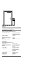
1
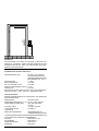
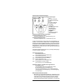
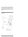
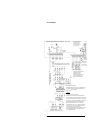
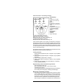
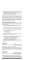
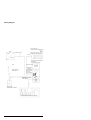
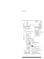
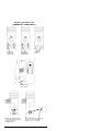
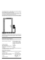
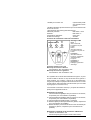
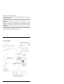
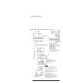
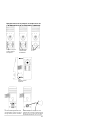
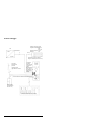
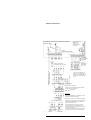
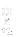
®
deutsch
english
français
italiano
SICHERHEIT UND PRÄZISION
SECURITY AND PRECISION
SECURITE ET PRECISION
SICUREZZA E PRECISIONE
Fluchttür-Steuerterminal
Emergency exit
control terminal
Terminal de commande
pour issues de secours
Terminale di controllo per
le uscite d’emergenza
1340-10/11
24 V- Ausführung
D 00081 01
deutsch
BEDIENUNGS-ANLEITUNG
english
OPERATING INSTRUCTIONS
français
MODE D’EMPLOI
italiano
ISTRUZIONI D’USO
deutsch
Inhaltsverzeichnis
Fluchttür- Steuerterminal 1340-10(11)
Seite
24V-Ausführung
Installation
4
4
Elektrotechnische Daten
5
Zusätzliche Steuer- und Überwachungselemente
6
Rückmeldekontakte/Türkontakte
6
Verriegelung des Fluchttür- Steuersystems
7
Funktionszustand Verriegelung
7
Entriegelung des Fluchttür- Steuersystems
7
Funktionszustand Entriegelung
7
Notentriegelung des Fluchttür- Steuersystems
8
Funktionszustand Notentriegelung
8
Sabotagemeldung
8
Rückstellung des Funktionszustandes „Notentriegelung“
8
Verkabelungsplan
9
Anschlußplan
Ersetzen der Glühlampe im NOT-AUF-Schalter
10
11
®
english
Contents
Escape door Control Terminal 1340-10(11)
Page
24 V
12
Installation
12
Electrotechnical specifications
13
Supplementary control and monitoring elements
14
Monitoring Contacts/Door contacts
14
Locking the escape door control system
15
Locked status
15
Unlocking the escape door control system
15
Unlocked status
15
Emergency unlocking of the escape door control system
15
Emergency unlocking status
16
Sabotage signal
16
Cancelling the „Emergency unlocking“ status
16
Wiring diagram 1340.10-93-00
17
Terminal plan 1340.10-94-00
18
Replacing the bulb in the emergency open switch
19
2
français
Sommaire
Terminal de commande 1340-10(11)
Page
24 V
20
Installation
20
Spécifications électrotechniques
21
Eléments de commande et de surveillance additionnels
22
Contacts de fond de pêne / Contacts de porte
23
Condamnation
Etat de la condamnation
23
23
Décondamnation
24
Etat de la décondamnation
24
Décondamnation d’urgence
24
Etat de la décondamnation d’urgence
24
Message de sabotage
24
Remise à zéro après „Décondamnation d’urgence“
24
Plan de câblage 1340.10-93-00
Plan de raccordement 1340.10-94-00
25
26
Remplacement de la lampe à incandescence de
l’interrupteur d’ouverture d’urgence
27
®
italiano
Sommario
Terminale di controllo 1340-10 (11)
24 V
Installazione
Specifiche elettrotecniche
Elementi di comando e di controllo supplementari
Contatti di retrosegnalazione/contatti porta
Bloccaggio del sistema per porte d’emergenza
Stato di chiusura
Sbloccaggio del sistema per porte d’emergenza
Stato di apertura (stato aperto)
Sbloccaggio d’emergenza del sistema
Stato di apertura d’emergenza
Segnale di sabotaggio
Ripristino dopo lo stato di ”apertura d’emergenza”
Schema cablaggio 1340.10-93-00
Schema connessioni 1340.10-94-00
Sostituzione della lampada ad incandescuena
nell’interrutore d’emergenza
Pagina
28
28
29
30
30
31
31
31
31
32
32
32
32
33
34
35
3
deutsch
Das effeff-Fluchttür- Steuerterminal 1340-10(11) in Kompaktbauweise beinhaltet eine Steuerzentrale für die Ansteuerung von
1 Tür bzw. von 2 Verriegelungselementen. Das effeff-FluchttürSteuerterminal besitzt kein eingebautes Netzteil; dadurch muß
eine bauseitige Stromversorgung mit Sicherheitskleinspannung
24 VDC (stabilisierte Gleichspannung) vorgesehen werden.
Als jeweilige Zentrale für die 3 effeff-Fluchttür-Basissysteme kann
somit ein Optimum an Kompaktheit erzielt werden. Drei unterschiedliche Ruhestrom- Verriegelungselemente unterstützen hierzu ein Maximum der Einsatzbereiche.
Basissystem A
Fluchttür-Steuerterminal 1340-10(11)
Türkontakt 10365
Türverriegelungselement 827-../828-../829-..
Basissystem B
Fluchttür-Steuerterminal 1340-10(11)
Türkontakt 10400
Türverriegelungselement Elektro-Paniköffner 3150
Basissystem C
Fluchttür-Steuerterminal 1340-10(11)
Türverriegelungselement Elektro-Fluchttüröffner
331 RR AKRR mit passendem Fallschloß 807
Vorgenannte Fluchttürsteuerungs-Basissysteme entsprechen den
bauaufsichtlichen Anforderungen an elektrische Verriegelungen
von Türen in Rettungswegen.
Das Steuerterminal 1340-10(11) bildet bei diesen 3 dezentral
aufgebauten Basissystemen das eigentliche Schalt-, Steuer- und
Überwachungselement.
3 Kontroll-LED´s signalisieren die Funktionszustände.
Ein integrierter Notschalter befehligt die unverzügliche Entriegelung
des Verriegelungselementes.
Installation
Die fachmännische Installation der effeff-Fluchttürsteuersysteme
muß entsprechend den „Bauaufsichtlichen Anforderungen an elektrische Verriegelungen von Türen in Rettungswegen“ erfolgen.
Auch die in den Sonderbauverordnungen festgelegten Bestimmungen müssen genau beachtet werden.
Bei der Installation des Systems sind desweiteren die VDE- und die
örtlichen EVU- Vorschriften zu beachten.
Die Verbindungen zwischen Steuerterminal und externen Geräten
sind nach Anschlußplan herzustellen. Es ist empfehlenswert, das
Verriegelungselement mit einem separaten Kabel anzufahren
(Induktion beim Schalten der Spule).
Aus Gründen der EMV- Sicherheit sollten nur abgeschirmte Leitungen verlegt werden. In Gebäuden mit starker Störbeeinflussung
empfiehlt sich der Einsatz von mehrfach geschirmten Leitungen,
auch zum Verriegelungselement.
Vor dem Einschalten ist die Spannungsversorgung von 24 VDC
(stabilisierte Gleichspannung) sicherzustellen.
4
max. 1050 mm
1234567890123456789012345678901212
1234567890123456789012345678901212
1234567890123456789012345678901212
1234567890123456789012345678901212
Installation:
Das Türterminal muß neben der Türzarge in Höhe des Türdrückers so angebracht werden, daß der Mittelpunkt des Notschaltelementes die max. Höhe von 1050 mm über dem Fertigfußboden nicht überschreitet .
Elektrotechnische Daten
Fluchttür-Steuerterminal 1340-10(11)
Nennbetriebsspannung
24 VDC/± 15% Toleranz
Sicherheitskleinspannung
(stabilisierte Gleichspannung
Restwelligkeit max. 1Vss)
Stromaufnahme:
1,0 ADC
Davon Eigenbedarf:
0,17 ADC
Für ext. Verbraucher max.:
0,83 ADC
Sicherung Betriebsspannung (F1): 1,0 AT
Sicherung F2
100 mAT
Die Sicherung F2 muß entfernt werden, wenn die Verriegelungselemente Typ 827.., 3150.. oder 331.. eingesetzt werden.
Technische Daten:
Stabiles Kunststoffgehäuse mit transparenter, nicht splitternder
Kunststoffabdeckung
Gehäusefarbe
Grün RAL 6032
Gehäuseabmessungen (b x h x t) ca. 92,5 x 250 x 98 mm
Notschaltelement beleuchtet
nach DIN VDE 0660
Teil 200
3 Anzeige- LED´s
rot, grün und gelb
1 akustisches Signal
107 dB/1 m
1 Zylinder für
Schlüsselschalterfunktion
Halbprofilzylinder mit
Schließbartstellung 90° links
1 nachleuchtende Kunststoff-Folieneinlage für Notschalterkennung
1 nachleuchtendes Piktogramm (selbstklebend)
Schutzart
DIN 40050 - IP 20
Feuchteklasse
DIN 40050 - F
Umgangstemperatur
0° bis 40° C
Einbaulage
senkrecht
5
Steuerfunktionen/Rückmeldungen
LED-Anzeigen
rot =
Fluchttür verriegelt,
Türüberwachung aktiv
grün =
rot
gelb
grün
Fluchttür entriegelt,
Türüberwachung
nicht aktiv
grün/gelb =
Fluchttür notentriegelt,
Signalisierung
„Notentriegelung“
grün/gelb bzw.
rot/gelb =
Sabotage, Signalisierung "Sabotage"
Schlüsselschalter Funktionsstellungen
kurzzeitige Betätigung rechts =
Fluchttürverriegelung "ein", Türüberwachung "ein"
kurzzeitige Betätigung links =
Fluchttürverriegelung "aus", Türüberwachung "aus"
Ist der Funktionszustand des Systems auf Notentriegelung geschaltet, so kann dieser Zustand durch kurzzeitige Schlüsseldrehung nach links zurückgestellt werden. Voraussetzung hierfür
ist, daß die Ursache der Meldung "Notentriegelung", die durch den
Notschalter bzw. andere externe Kontakte geschaltet wurde, zurückgestellt wird (Sehen Sie hierzu den Abschnitt Rückstellung/
Wiederverriegelung).
Am Fluchttür-Steuerterminal 1340-10(11) sind folgende Eingänge
für externe Geräte vorgesehen.
Verriegelungselemente
Flächenhaftmagnet 827
(max. 2 Stück, nur für Parallelbetrieb)
oder Flächenhaftmagnet 828
(max. 2 Stück, nur für Parallelbetrieb)
oder Flächenhaftmagnet 829 (1 Stück)
oder Elektro-Paniköffner 3150
(max. 2 Stück, nur für Parallelbetrieb)
oder Fluchttüröffner 331 RR AK RR
(max. 2 Stück, nur für Parallelbetrieb)
Zusätzliche Steuer- und Überwachungselemente
Zentraltableau 725
Türrückmeldekontakt (z.B. Kegelkontakt 10400)
Brandmeldeanlage (Linienansteuerung)
externe Anzeigeelemente für die Funktionszustände
(Türentriegelung, Türverriegelung, Tür-Notentriegelung
und Sabotage)
Rückmeldekontakte/Türkontakte
! Bei Einsatz von Flächenhaftmagneten bzw. Paniköffnern 3150
als Türverriegelungselement ist es erforderlich, daß ein externer
Türkontakt in das Türelement eingebaut wird. Durch diesen
Türkontakt wird dem Fluchttürsteuerungssystem übermittelt,
daß die entsprechende Fluchttür zugemacht ist, um somit eine
6
funktionelle Verriegelung zu gewährleisten.
Beim Einsatz des Fluchttüröffners 331 RR AK RR als Türverriegelungselement ist kein zusätzlicher Türkontakt erforderlich,
da der Überwachungskontakt, der den Türzustand (Tür offen/
Tür zu) überwacht, im Fluchttüröffner integriert ist. Dieser Schaltkontaktsatz schaltet ein Signal, sobald die Schloßfalle in den
Türöffner eingreift.
Ein weiterer Schaltkontaktsatz, der in den Fluchttüröffnerverriegelungselementen (außer den Flächenhaftmagneten 827)
integriert ist, stellt sicher, daß die Türverriegelung effektiv realisiert
ist. Dieses Signal wird durch ein Hall-Element bei Flächenhaftmagneten bzw. durch einen Ankerkontakt im Paniköffner sowie im
Fluchttüröffner geschaltet und an das Fluchttürsteuergerät zur
Auswertung weitergeleitet.
Verriegelung des Fluchttür-Steuersystems
Nach erfolgtem Anschluß und der Überprüfung der Anlage müssen
die Funktionen des Fluchttürsteuerterminals 1340-10(11) geprüft
werden (Entriegelung, Notentriegelung und Rückstellung).
Hierzu muß die Fluchttür zunächst zugemacht werden, dadurch wird auch der Türkontakt (Ruhestromlinie-Türkontakt)
geschlossen.
Der Notschalter (im Steuerterminal) darf nicht gedrückt sein,
evtl. manuelle Entriegelung des Nottasters vornehmen.
Einschalten des Fluchttür- Steuersystems
durch Schlüsselschalterbetätigung kurzfristig nach rechts
"Türverriegelung ein"
"Türüberwachung ein"
Am Steuerterminal leuchtet die rote LED und übermittelt den
Funktionszustand "Fluchttür verriegelt".
Wird das Fluchttürsteuerungssystem am Steuerterminal auf den
Funktionszustand "Tür verriegelt" geschaltet, obwohl:
der Notschalter betätigt worden ist
evtl. die Brandmeldeanlage ausgelöst hat,
schaltet das Fluchttür-Steuerungssystem sofort in den Funktionszustand "Notentriegelung". Dies ist auch bei Netzwiederkehr
nach einem Stromausfall die Folge.
Funktionszustand - Verriegelung
Verriegelungselement
= verriegelt
LED-Anzeige am Steuerterminal = rote LED leuchtet
(auch extern übertragbar)
Entriegelung des Fluchttür-Steuerungssystems
Wird der Schlüsselschalter im Steuerterminal kurzzeitig nach links
gedreht, entriegelt das Verriegelungselement. Am Steuerterminal
leuchtet die grüne LED und signalisiert den Funktionszustand
"Fluchttür entriegelt".
Funktionszustand - Entriegelung
Verriegelungselement
= entriegelt (stromlos)
LED-Anzeige im Steuerterminal
= grüne LED leuchtet
(auch extern übertragbar)
7
Notentriegelung des Fluchttür-Steuerungssystems
! Bei Betätigung des Notschalters im Steuerterminal wird sofort
das Verriegelungselement entriegelt. Dabei bleibt das Notschalter-Schaltelement in der Schaltstellung "Notentriegelung"
bis zur manuellen Rückstellung.
! Bei System-Verknüpfung mit einer Brandmeldeanlage wird die
externe Ruhestrom-Ansteuerung auf 2 redundant arbeitende
Relais vorgenommen (Anschlußklemmen 18/19). Die Versorgungsspannung kann hierzu an den Anschlußklemmen 1 und
! 2 des Fluchttürsteuergerätes abgegriffen werden oder durch
eine externe Stromversorgung 24 VDC erfolgen.
Ist keine verknüpfbare Brandmeldeanlage vorhanden, so müssen die Relais (Anschlußklemmen 18/19) direkt an die
Versorgungsspannung der Anschlußklemmen 1/2 angeschlossen werden.
! Am Steuerterminal leuchten die grüne und die gelbe LED und
übermitteln den Funktionszustand „Notentriegelung“. Desweiteren wird ein Melderelais im Fluchttürsteuergerät an
gesteuert, das die Notfallsituation signalisiert.
Funktionszusstand - Notentriegelung
Verriegelungselement
= entriegelt (stromlos)
LED-Anzeige im Steuerterminal
= gelbe und grüne LED
leuchten gemeinsam
(auch extern übertragbar)
akustischer Signalgeber im Steuerterminal
= Ansteuerung
(auch extern übertragbar)
Sabotagemeldung am Steuerterminal 1340-10(11)
Wird das Gehäuse des Steuerterminals geöffnet, schaltet sofort ein
Sabotagekontakt (Ruhestromkontakt) die Meldung "Sabotage".
Durch diese Meldung wird der akustische Signalgeber angesteuert.
Am Steuerterminal ist die Meldung durch das Leuchten der gelben
LED erkennbar. Sobald das Gehäuse des Steuerterminals wieder
geschlossen wird, erlischt die optische Anzeige „Sabotage“ und die
akustischen Signalgeber werden abgeschaltet.
Durch die "Sabotagemeldung" wird das Verriegelungselement
der Fluchttür nicht entriegelt. Der Funktionszusstand (entriegelt/
verriegelt) des Fluchttür-Steuersystems bleibt erhalten.
Funktionszustand - Sabotagemeldung
Verriegelungselement
= der momentane Schaltzustand bleibt erhalten
LED-Anzeige im Steuerterminal
= zur momentanen Schaltzustandsanzeige leuchtet eine gelbe
LED (auch extern übertragbar)
akustischer Signalgeber im Steuerterminal
= Ansteuerung (auch extern übertragbar)
Rückstellung des Funktionszustandes „Notentriegelung“
und ggf. Wiederverriegelung
Um den Funktionszustand "Notentriegelung" am Steuerterminal
zurückstellen zu können, muß die evtl. geöffnete Tür zugemacht
werden. Desweiteren muß der Notschalter wieder in die Bereitschaftsstellung gebracht werden.
Bei System-Verknüpfung mit Brandmeldeanlagen muß eine Systemrückstellung an den Brandmeldeanlagen erfolgen.
8
Sind v.g. Punkte berücksichtigt, so kann das Fluchttürsteuerungssystem am Steuerterminal zurückgeschaltet werden. Hierzu muß
der Schlüsselschalter kurzzeitig nach links gedreht werden.
Soll die Türverriegelung wieder aktiviert werden, so muß der
Schlüsselschalter kurzzeitig nach rechts gedreht werden. Als
Bestätigung der Wiederverriegelung leuchtet eine rote LED am
Steuerterminal.
Verkabelungsplan
Türverriegelung ww.
Haftmagnet Modell 828 (2x)
829,
827 (2x)
Elektropaniköffner 3150
Fluchttüröffner
331
Netz
Netzgerät
230V
2
max.5
24VDC
Türterminal
mit integrierter Fluchttürsteuerung
1340-10 (24V- Ausführung)
BMA
(Wenn vorhanden)
(Alarmhupe)
(AnzeigeLED- rt/gn/ge)
Entriegelung über
Brandmeldeanlage
2
2
(Schlüsselschalter Verriegeln/
Entriegeln,
Alarm löschen)
(NOT-AUF-Schalter, beleuchtet)
NOT
AUF
7
Türkontakt
(entfällt bei
Modell 331)
Zentraltableau 725 (bei Bedarf)
9
Betriebsspannung
Relais K9, K10
24VDC ±15%
Stromaufnahme:
max. 40mA
+24V
+24V
K9
F2
0,1AT
+24V
+24V
1,82k
Fluchttür-Steuerterminal 1340-10 (24- Volt)
K10
K9
+24V
K4
NOT-AUFSchalter
F1
1AT
K10
X1
1
2
3 4 5
X2
8 9 10
6 7
Betriebsspannungsmeldung
Anschlußplan
11 12 13 14 15 16 17 18 19 20
(2)
+24V
(1)
X1.3 X1.4
Spannungsversorgung 24V DC ±15%
Sicherheitskleinspannung
+ -
1 2
9 10
Zentraltableau 725
5
4
6
3
Haftmagnet 828
6
7 8
X1: 5
4
1 2
10
9
5
1 2
6
3
3
7 Bei Fremdspannungsversorgung:
24 V ± 15%
Alarm
8
7
entriegelt
6
8 4 5 6
rt gn ge
verriegelt
X1: 5
Entriegeln
Rückmeldekontakt der Tür erforderlich
bei den Modellen 827, 828, 829, 3150
Verriegeln
2
1
Brandmeldeanlage*)
4
*)Wenn keine Brandmeldeanlage vorhanden:
Verbindungen von
Klemme 1 auf Klemme 19
und von Klemme 2 auf
Klemme 18 vornehmen.
5
6
1 Haftmagnet 829 oder 2x Haftmagnet 828
X1: 5
7 8 9 10
Bei Modell 827 beachten:
Dx
ws
br
gn
ge
ws
br
gn
ge
Dx
2 Haftmagnete 827
7
X1: 5
8
Funkenlöschdioden Dx an der Anschlußklemme
des Haftmagneten wie gezeichnet anklemmen.
=
Type 1N4007
Achtung!
9 10
Auf richtigen Anschluß achten.
Bei falschem Anschluß keine Garantieleistung.
gn ge gr
X1: 3 4
rt
bl
Elektro-Paniköffner
3150
5
7 8 9 10
bl
rt
rt
gn
bl
rt
gn
bl
Rückmel- Anker- Fluchttürdekontakt kontakt öffner 331
10
Die einschlägigen VDE-Vorschriften sowie die Bestimmungen des örtlichen EVU sind zu beachten.
Sicherung F2 ist nur bei dem Haftmagnet Modell
828 und 829 erforderlich. Bei allen anderen
Modellen ist die Sicherung F2 zu entfernen!
Steuerleitungen max. 100 m, Mindestdurchmesser 0,6 mm. Leitungen zum Netzteil und Verriegelungselement: Länge max. 300 m.
Der Leitungsquerschnitt ist so zu bemessen, daß
am Verriegelungselement eine Spannung von
24 V gewährleistet ist.
Ersetzen der Glühlampe im NOT-AUF-Schalter
1.
TransparentKunststoffhaube
abnehmen
2.
Aufkleber
”NOT-AUF”
entfernen
3.
Schrauben
lösen
4.
Oberteil
abnehmen
5.
Arretierung des Schalterelements
lösen. Arretierungshebel in Stellung
”AUF” drehen.
6.
Glühlampe herausnehmen und durch
Glühlampe BA 9 s 24-30 V 1,2 W bzw.
Glühlampe BA 9 s 12-15 V 1,2 W
ersetzen.
11
english
The compact-design effeff escape door control terminal
1340-10(11) is fitted with a central control circuit which triggers 1
door or 2 locking elements. The effeff escape door control terminal
has its own built-in power supply unit which must be fed with 24 VDC
stabilized direct voltage supply provided at the installation site.
Used as a central control system for the 3 basic effeff escape door
systems, it is therefore possible to achieve extremely compact
installation. Three different normally open locking elements permit
maximum scope of application.
Basic system A
Escape door control terminal 1340-10(11)
Door contact 10365
Door locking element 827-../828-../829-..
Basic system B
Escape door control terminal 1340-10(11)
Door contact 10400
Door locking element electric panic opener 3150
Basic system C
Escape door control terminal 1340-10(11)
Locking element
Electric escape door lock release 331 RR AKRR
with matching latch bolt 807
The above basic escape door control systems conform to building
regulations governing electrical locking devices on doors in escape
routes.
The control terminal 1340-10(11) forms the actual switching,
control and monitoring element of these three decentrally installed
basic systems. Operating statuses are indicated by 3 pilot lamps.
An integrated emergency switch effects immediate unlocking of
the locking element.
Installation
effeff escape door control systems must be installed correctly in
compliance with the valid „Building regulations governing electrical
locking device on doors in escape routes“. The provisions of special
codes of building practice must also be observed precisely.
When installing the system, the locally applicable electricity board
and electrical engineering association regulations must be followed.
Connect the control terminal and external appliances in accordance
with the terminal plan. We recommend running a separate cable to
the locking element (induction on energising the coil).
To ensure electro-magnetic compatibility, only lay shielded
conductors. In buildings subject to strong magnetic or disturbing
fields, we recommend using multiple-shielded conductors, also to
the locking element.
Before switching on, ensure a voltage supply of 24 VDC (stabilized
direct current).
12
max. 1050 mm
1234567890123456789012345678901212
1234567890123456789012345678901212
1234567890123456789012345678901212
1234567890123456789012345678901212
Installation
The control terminal must be mounted next to the door frame at
the height of the door handle in such a way that the central point
of the emergency switching element does not exceed a height of
max. 1050 mm above the final floor level.
Electrotechnical specifications
Escape door Control Terminal 1340-10(11)
Rated operating voltage:
24 VDC / ±15% tolerance
Safety extra-low voltage
Stabilized direct voltage
residual ripple max. 1Vss
Current consumption:
1.0 ADC
Of which auxiliaries service:
0.17 ADC
For external loads:
0.83 ADC
Operating voltage fuse (F1):
1.0 AT
Fuse F2:
100 mAT
Fuse F2 must be removed if the locking elements Type 827..,
3150.. or 331.. are used.
Specifications:
Stable plastic housing with transparent,
non-splintering plastic cover
Housing colour
Green RAL 6032
Housing dimensions (w x h x d)
appr. 92.5 x 250 x 98 mm
Emergency switching element,
illuminated
as per DIN VDE 0660
part 200
3 display LEDs
red, green and yellow
1 acoustic signal
107 dB/1 m
1 cylinder for key-operated switch Half-profile cylinder with left
hand function locking
lever at 90°
1 luminescent plastic foil inlay for emergency switch recognition
1 luminescent pictogram (self-adhesive)
Protection class
DIN 40050 - IP 20
Humidity class
DIN 40050 - F
Ambient temperature
0° to 40° C
Mounting position
Vertical
13
Control functions / monitoring contacts
LED displays
red
green
yellow
red =
Escape door in locked
status, Door monitoring
active
green =
Escape door in unlocked
status Door monitoring not
active
green/yellow =
Escape door in emergency
unlocked statusSignal
"emergency unlocked
status"
green/yellow or
red/yellow =
Sabotage
Signal "Sabotage"
Key-operated switch positions:
Right-hand momentary contact =
Escape door lock "on", Door monitoring "on"
Left-hand momentary contact =
Escape door lock "off", Door monitoring "off"
If the functional status of the system is switched to emergency
unlocking, this status can be cancelled by briefly turning the keyoperated switch to the left. This is only possible if the cause of the
„Emergency unlocking“ signal activated by the emergency switch
or other external contacts has been remedied and reset (see
section Cancel/Relocking).
The following inputs for external appliances are provided for at the
Escape Door Control Terminal 1340-10(11).
Locking elements
Surface holding magnet 827 (max. 2 magnets, only for parallel
operation)
or Surface holding magnet 828 (max. 2 magnets, only for parallel
operation)
or Surface holding magnet 829 (1 magnet)
or Electric panic opener 3150 (max. 2 openers, only for parallel
operation)
or Escape door lock release 331 RR AK RR (max. 2 releases,
only for parallel operation)
Supplementary control and monitoring elements
Central indicator board 725
Door monitoring contact (e.g. cone contact 10400)
Fire alarm (line control)
external display elements for operating statuses (door unlocking,
door locking, door emergency unlocking and sabotage)
Monitoring contacts/door contacts
! When using surface holding magnets or panic openers 3150 as
a door locking element, it is necessary to mount an external
door contact in the door element. This door contact informs the
escape door control system that the respective escape door
has been closed to guarantee a functional locking process.
When using the escape door lock release 331 RR AK RR as a
14
door locking element, no additional door contact is necessary,
as the monitoring contact for door status (door open/door shut)
is integrated in the escape door lock release.
This switching contact assembly gives off a signal as soon as
the latch bolt engages in the lock release.
A further switching contact assembly integrated in the escape door
lock release locking elements (with the exception of surface
holding magnet 827) ensures that the door has effectively been
locked. This signal is switched by a Hall-effect element in the case
of surface holding magnets and by an armature contact in the panic
opener and the escape door lock release, and is transmitted for
evaluation to the escape door control unit.
Locking the escape door control system:
After connecting and checking the system, test the function of the
escape door control terminal 1340-10(11) (unlocking, emergency
unlocking and reset).
For testing, first close the escape door. This also closes the
door contact (closed current line door contact).
The emergency switch (in the control terminal) must not be
pressed, if necessary unlock the emergency switch manually.
Switch on the escape door control system by activating the
key-operated switch briefly to the right
"Door locking on"
"Door monitoring on"
The red LED lights up on the control terminal and transmits the
operating status „Escape door locked“.
If the escape door control system is switched at the control
terminal to the „Door locked“ status, even though
the emergency switch has been activated
a possible fire alarm has been triggered
the escape door control system switches immediately to the
"Emergency unlocking" operating status.
This also results after power returns to the system following a
failure.
Locked status
Locking element
LED display at the control terminal
= locked
= red LED alight (external
transmission also possible)
Unlocking the escape door control system
If the key-operated switch in the control terminal is briefly turned to
the left, the locking element is unlocked. At the control terminal, the
green LED and signals the "escape door unlocked" operating
status.
Unlocked status
Locking element
= unlocked (not energized)
LED display in the control terminal = green LED alight (external
transmission also possible)
Emergency unlocking of the escape door control system
! When the emergency switch in the control terminal is activated,
the locking element is immediately unlocked. During this process
15
the emergency switch element remains in the "Emergency
unlocking" switching position until manually reset.
! When the system is linked to a fire alarm, external closedcurrent tripping is executed on two redundant operating relays
(terminals 18/19). For this, the supply voltage can be picked off
at terminals 1 and 2 of the escape door control unit or through
an external 24 VDC power supply.
! If there is no fire alarm unit available which is capable of link-up
to the escape door system, the relays (terminals 18/19) must be
connected directly to the supply voltage of terminals 1/2.
! At the control terminal, the green and yellow LED light up and
transmit the „Emergency unlocking“ operating status.
In addition, a signal relay is triggered in the escape door control
unit which signals the emergency situation.
Emergency unlocking status
Locking element
= unlocked (not energized)
LED display in the control terminal = yellow and green LEDs light
up simultaneously (external
transmission also possible)
Acoustic signal encoder in control terminal
= triggering (external transmission also possible)
Sabotage signal at control terminal 1340-10 (11)
If the housing of the control terminal is opened, a sabotage contact
(normally open contact) immediately activates a "Sabotage" signal.
This signal triggers the acoustic signal encoder. The sabotage
status is indicated at the control terminal by the yellow LED. As soon
as the housing of the control has been closed again, the optical
"sabotage" display is extinguished and the acoustic signal encoders
are switched off.
The locking element of the escape door is not unlocked by the
"sabotage signal". The operating status (unlocked/locked) of the
escape door control system is retained.
Operating status - sabotage signal
Locking element
= the current switching status is retained
LED in the control terminal
= for the current switching status display, a yellow LED is alight
(external transmission also possible).
Acoustic signal encoder in the control terminal
= Triggering (external transmission also possible).
Cancelling the "Emergency unlocking" status
and relocking if required
To cancel the "Emergency unlocking" operating status at the control
terminal, any door which has been opened must be closed.
In addition, the emergency switch must be returned to the stand-by
setting.
Where the system is linked to fire alarms, a system reset process
must also take place for the fire alarms.
Once the above points have been observed, it is possible reset the
escape door control system at the control terminal. To do this, turn
the key-operated switch briefly to the left.
If you wish to reactivate the door locking function, briefly turn the
key-operated switch to the right. To confirm that the door has been
relocked, a red LED lights up at the control terminal.
16
Wiring Diagram
Door locking with
Holding magnet model 828 (2x)
829,
827 (2x),
Electric panic opener 3150
Escape door lock release 331
Mains
Power supply unit
230V
2
max.5
24VDC
Door terminal with integrated
escape door
control 1340-10 (24 V)
FAS
(Acoustic alarm)
Unlocking via fire
alarm system
(Display LED
rd/gn/ye)
(Key- operated
switch lock/unlock to extinguish alarm)
2
2
(EMERGENCY OPEN
switch lights up)
NO T
AUF
7
Door contact
(omitted with model 331)
Central indicator panel 725 (if required)
17
Escape door control terminal 1340-10 (24 V)
Operating voltage
Relais K9, K10
24VDC ±15%
Current consumption:
max. 40mA
+24V
K9
F2
0,1AT
+24V
K10
+24V
1.82k
+24V
K9
+24V
K4
F1
1AT
EMERGENCY OPEN switch
K10
Operating voltage signal
Terminal plan
X1
1
2
3 4 5
6 7
X2
8 9 10
11 12 13 14 15 16 17 18 19 20
Fire alarm
(2)
system *)
+24V
(1)
7
1 2
9 10
5
4
Lock
With externally
supplied voltage:
24 V ± 15%
*) If no fire alarm system
is provided: Connect terminal 1
to terminal 19 and
terminal 2 to terminal 18.
6
3
Holding magnet 828
7 8 9
6
X1: 5
1 2
7
Central indicator panel 725
5
4
10
1 2
4
5
ye
wh
br
gn
ye
6
3
3
6
1 holding magnet 829 or 2x holding magnet 828
7 8 9 10
X1: 5
For model 827, observe:
Connect spark suppression diode Dx
to the terminal of the holding magnet as
Dx
Dx
drawn:
Type 1N4007
=
wh
br
gn
Voltage supply 24 V DC ±15%
Safety extra-low voltage
+ -
6
8
8 4 5 6
rd gn ye
Unlocked
Alarm
X1: 5
2
Locked
Door monitoring contact necessary
in the models 827, 828, 829, 3150
1
Unlock
X1.3 X1.4
2 holding magnets 827
7
X1: 5
gn ye gr
X1: 3 4
8
9 10
rd bl
Electric panic
opener 3150
7 8 9 10
5
bl
rd
rd
gn
bl
rd
gn
bl
Escape
Monitoring Armature door lock
contact contact release 331
18
Caution!
Check that connections are correctly executed.
Incorrectly connected systems result in
forfeiture of guarantee cover.
Observe the valid VDE regulations and the
stipulations of your local electricity board.
Fuse F2 is only necessary with model 828 and 829.
With all other models fuse F2 has to be removed!
Control conductors max. 100 m in length,
minimum cross-section dia. 0.6.
Conductors to the power supply
unit and locking element: max. length 300 m.
The conductor cross-section must be gauged
so that a voltage of 24 V is guaranteed at the
locking element.
Replacing the bulb in the
EMERGENCY OPEN SWITCH
2.
Take off the
EMERGENCY
OPEN sticker
1.
Remove the
transparent
plastic cowl
3.
release the
screws
4.
Take off the top
of the housing
5.
Release the arrest mechanism
of the switch element. Turn the
arresting lever to the
”OPEN” position
6.
Take out the bulb and replace it by a
BA 9 s 24 - 30 V 1.2 W bulb or
BA 9 s 12 - 15 V 1.2 W bulb
19
français
Le terminal de commande 1340-10(11) effeff pour les issues de
secours est caractérisé au premier coup d’oeil par une forme
compacte. Il intègre la centrale destinée à la commande d’1 porte,
autrement dit de deux éléments de verrouillage, mais aucune boîte
d’alimentation. Par conséquent, il est indispensable de préparer le
lieu de montage en installant une alimentation électrique de
24 V CC (courant continu stabilisé).
Comme centrale de commande des 3 systèmes de base proposés
par effeff pour le verrouillage des issues de secours, c’est la
solution qui présente le maximum de compacité. Les trois différents
éléments de verrouillage (courant repos) proposés couvrent
largement les diverses exigences en matière de fermeture des
issues de secours.
Système de base A :
Terminal de commande 1340-10(11)
Contact de porte 10365
Elément de verrouillage :
Ventouse électromagnétique 827-../828-../829-..
Système de base B :
Terminal de commande 1340-10
Contact de porte 10400
Elément de verrouillage :
Gâche antipanique 3150
Système de base C :
Terminal de commande 1340-10
Elément de verrouillage :
Gâche électrique pour issues de secours
331 RR AK RR avec contrepartie 807
Les systèmes de verrouillage des issues de secours proposés par
effeff satisfont aux directives définies en matière de sécurité pour
l’évacuation des locaux en cas de danger.
Dans ces trois systèmes de base en configuration autonome, le
terminal de commande 1340-10(11) représente l’élément de
pilotage et de surveillance proprement dit.
3 LEDs visualisent les différents états du terminal de commande.
Un bouton de secours intégré permet de décondamner la porte
sans délai.
Installation
L’installation du matériel par des professionnels doit respecter les
contraintes et les servitudes imposées en la matière par les
services de réglementation concernant la fermeture et le verrouillage
électrique des issues de secours dans les bâtiments.
Les clauses spécifiques en vigueur pour des bâtiments à usage
particulier sont à respecter également.
A l’installation, il convient d’autre part, de se conformer aux
règlements VDE et EVU en vigueur, selon les endroits.
Procéder au raccordement entre le terminal de commande et les
appareils externes, conformément au plan de raccordement. Il est
20
max. 1050 mm
recommandé de poser un câble distinct pour alimenter l’élément
de verrouillage (pour cause d’induction).
Pour des raisons de sécurité, il est obligatoire de poser des câbles
avec écran. Dans les bâtiments présentant un fort parasitage, il est
recommandé d’utiliser des câbles multi-écrans.
Avant de mettre le terminal de commande sous tension, s’assurer
de la présence d’un couran"t de 24 V cc (courant continu stabilisé).
1234567890123456789012345678901212
1234567890123456789012345678901212
1234567890123456789012345678901212
1234567890123456789012345678901212
Installation:
Le terminal de commande est à installer à proximité du chambranle à la
hauteur du b"outon-poussoir, de façon à ce que le centre du bouton de
secours ne se situe pas à une hauteur supérieure à 1500 mm au-dessus
du plancher terminé.
Spécifications électrotechniques
Terminal de commande 1340-10(11) pour issues de secours
24 VCC, tolérance ±15%
Tension réduite de sécurité
(Tension continue stabilisée,
ondulation résiduelle 1Vss)
Intensité absorbée:
1,0 ACC
dont besoin propre:
0,17 ACC
Pour consommatuers ext., max,: 0,83 ACC
Fusible tension d’exploitation (F1): 1,0 AT
Fusible F2:
100 mAT
Le fusible F2 doit être retiré si l’on met en place les éléments de
verrouillage du type 827.., 3150..ou 331.
Tension de service nominale:
Spécifications techniques:
Coffret en matière plastique robuste avec enveloppe transparente
incassable
Couleur du boîtier
verte RAL 6032
Dimensions approx. du boîtier (l x H x P) 92,5 x 250 x 98 mm
Eclairage du bouton de secours
selon DIN VDE 0660,
partie 200
3 LEDs
rouge, verte, jaune
1 signal acoustique
107 dB/1 m
21
1 barillet pour fonction clé
Cylindre demi-profilé
avec panneton 90° à
gauche
1 feuillet en plastique photoluminescent pour reconnaissance du
bouton de secours
1 pictogramme (autocollant) photoluminescent
Classe de protection
DIN 40050 - IP 20
Humidité
DIN 40050 - F
Températures ambiantes
0°C à 40°C
Position de montage
verticale
Fonctions de commande / Retour d’informations
Affichages LED
rouge
verte
jaune
rouge =
issue condamnée,
surveillance de porte
activée
verte =
issue décondamnée,
surveillance de porte non
activée
verte/jaune =
issue décondamnée
d’urgence, signalisation
"Décondamnation
d’urgence"
verte/jaune ou
rouge/jaune =
Sabotage, signalisation
"Sabotage"
Fonctions activées par la clé
Bref coup de clé vers la droite =
Condamnation "ES" Surveillance "ES"
Bref coup de clé vers la gauche =
Condamnation "HS" Surveillance "HS"
Si le système est en état de décondamnation d’urgence, on peut
annuler cet état en donnant un coup de clé bref vers la gauche. Il
existe toutefois une condition: l’origine de la décondamnation
d’urgence qui a été provoquée par le bouton de secours ou un autre
contact externe, cette origine doit avoir été annulée (voir à cet effet
le paragraphe sur la remise à zéro).
Le terminal de commande 1340-10(11) comporte les entrées ciaprès pour les appareils externes:
Eléments de verrouillage
Ventouse électromagnétique 827 (au maximum 2 ventouses,
uniquement pour raccordement en parallèle)
ou Ventouse électromagnétique 828 (au maximum 2 ventouses,
uniquement pour raccordement en parallèle)
ou Ventouse électromagnétique 829 (1 ventouse)
ou Gâche antipanique 3150 (au maximum 2 gâches, uniquement
pour raccordement en parallèle)
ou Gâche électrique pour issues de secours 331 RR AK RR (au
maximum 2 gâches, uniquement pour raccordement en
parallèle)
Eléments de commande et de surveillance additionnels
! Tableau de centralisation 725
Contact de porte (par exemple contact à bille 10400)
22
Tableau de signalisation incendie (montage en boucle)
Eléments externes de signalisation des états de fonctionnement
(décondamnation, condamnation, décondamnation d’urgence
et sabotage)
Contacts de fond de pêne / Contacts de porte
! Quand on met en place des ventouses électromagnétiques ou
des gâches antipaniques 3150 comme éléments de verrouillage,
il est indispensable d’installer un contact de feuillure externe sur
la chambranle. La fonction de ce contact de porte est de signaler
! à la centrale de commande que la porte est fermée et que les
fonctions de verrouillage sont garanties.
Quand on met en place une gâche électrique pour issues de
secours 331 RR AK RR comme élément de verrouillage, le
! contact de porte n’est pas nécessaire : en effet, le contact de
surveillance de l’état de la porte (ouverte/fermée) est intégré
dans la gâche (contact de retour de fond de pêne).
Ce jeu de contacts adresse un signal dès que le pêne demi-tour
entre dans le demi-tour de la gâche.
Un autre jeu de contacts de porte intégré dans les éléments de
verrouillage des issues de secours (à l’exception des ventouses
électromagnétiques 827) est chargé de surveiller si le verrouillage
de la porte est effectivement réalisé. Ce signal est produit par l’effet
Hall dans la ventouse électromagnétique et par un induit sur la
gâche antipanique et la gâche électrique, puis adressé à la centrale
de commande qui l’exploite ensuite en conséquence.
Condamnation
Dès que l’installation électrique a été réalisée et vérifiée, il convient
de contrôler les fonctions du terminal 1340-10(11) (condamnation,
décondamnation et remise à zéro).
Il convient tout d’abord de fermer l’issue de secours pour fermer
le contact de porte (courant repos).
Le bouton de secours (sur le terminal) ne doit pas être pressé;
le cas échéant, procéder manuellement à son déblocage.
Actionner les fonctions du système en tournant brièvement la
clé vers la droite.
Condamnation "ES"
Surveillance "ES"
Sur le terminal de commande, la LED rouge s’allume signalant
ainsi l’état "Issue condamnée".
Si vous commutez la fonction "Issue condamnée" sur le
terminal, alors que :
le bouton de secours a été actionné,
le tableau de signalisation incendie a éventuellement
déclenché une alarme, alors le système de commande déclenche immédiatement l’état "Décondamnation d’urgence".
C’est également ce qui se passe au retour du courant après une
coupure.
Etat de la condamnation
L’élément de verrouillage est verrouillé.
La LED rouge sur le terminal de secours est allumée (elle peut être
reportée).
23
Décondamnation
Si vous tournez brièvement vers la gauche la clé du terminal,
l’élément de verrouillage sera décondamné. La LED verte s’allume
sur le terminal et signale l’état „Issue décondamnée“.
Etat de la décondamnation
L’élément de verrouillage est déverrouillé (absence de courant).
La LED verte sur le terminal est allumée (elle peut être reportée).
Décondamnation d’urgence
! Dès qu’on appuie sur le bouton de secours sur le terminal,
l’issue est décondamnée immédiatement. Le bouton de secours
reste enfoncé en position de décondamnation d’urgence,
jusqu’à ce qu’on le libère manuellement.
! Lorsque le terminal de commande est relié à un tableau de
signalisation incendie, une commande, à sécurité plus, active
les 2 relais qui fonctionnent en redondance (bornes de raccordement 18/19). La tension d’alimentation nécessaire peut être
prise aux bornes de raccordement 1 et 2 du terminal de
commande ou sur une alimentation externe 24 V cc.
! Si le terminal de commande n’est pas relié à un tableau de
signalisation, les relais (bornes de raccordement 18/19) sont à
raccorder directement sur la tension d’alimentation aux bornes
de raccordement 1/2.
! Sur le terminal, les LED verte et jaune s’allument signalant l’état
"Décondamnation d’urgence".
Par ailleurs, un relais de signalisation est activé dans la centrale
de commande pour signaler une situation d’urgence.
Etat de la décondamnation d’urgence
L’élément de verrouillage est déverrouillé (absence de courant)
Sur le terminal, les LED rouge et verte sont allumées ensemble (la
signalisation peut être reportée).
L’avertisseur acoustique est activé dans le terminal de commande
(cette fonction peut être reportée).
Message de sabotage sur le terminal 1340-10(11)
Dès que le boîtier du terminal est ouvert, un contact de sabotage
(contact courant repos) adresse le message „Sabotage“.
Ce message active l’avertisseur acoustique. Sur le terminal, la
LED jaune s’allume.
Dès que le boîtier est refermé, le signal acoustique et le signal
optique "Sabotage" sont arrêtés.
Le message "Sabotage" n’entraîne pas la décondamnation
de l’issue de secours. L’état du système de commande (ouvert/
fermé) reste inchangé.
Etat de sabotage
Elément de verrouillage = l’état actuel reste inchangé.
Sur le terminal de secours, une LED jaune s’allume (signalisation
pouvant être reportée).
L’avertisseur acoustique est activé sur le terminal (cette fonction
peut être reportée).
Remise à zéro après "Décondamnation d’urgence"
Afin que l’état „Décondamnation d’urgence“ puisse être désactivé
sur le terminal, il est peut-être nécessaire de refermer l’issue de
24
secours, si elle a été ouverte.
Il faut également débloquer manuellement le bouton de secours,
s’il a été actionné.
Lorsque le terminal de commande est en liaison avec un tableau
de signalisation incendie, il convient de remettre celui-ci à zéro
également.
Dès que les opérations précédentes ont été faites, on peut
réinitialiser (remettre à zéro) le système de commande des issues
de secours sur le terminal. Il suffit de tourner brièvement la clé vers
la gauche.
Pour réactiver la condamnation de la porte, tourner brièvement la
clé vers la droite. La condamnation de la porte est confirmée par
la LED rouge qui s’allume sur le terminal.
Plan de câblage
Secteur
Boîte d'alimentation
230V
2
Elément de verrouillage ww.
Ventouse électromagnétique 828 (2x)
829
827 (2x)
Gâche antipanique
3150
Gâche
331
max.5
24VDC
Terminal de commande 1340-10
(24V)
(Signal
acoustique)
TS
Dècondamnation via
tableau de signalisation
2
2
(LED r/v/j)
(Commutateur
à clé, Verrouiller,
déverrouiller,
arrêter l'alarme)
(BOUTON DE SECOURS,
éclairé)
NOT
AUF
7
Contact de porte
(néant sur modèle 331)
Tableau central 725 (si besoin est)
25
Plan de raccordement
+24V
Tension de service +24V
Relais K9, K10
24VCC ±15%
Intensité absorbée
max. 40mA
K9
+24V
1,82k
+24V
K9
F2
0,1AT
+24V
K10
K4
Bouton de secours
NOT-AUF
F1
1AT
K10
X1
1
2
3 4 5
6 7
X2
8 9 10
Signal tension de fonctionnement
Terminal de commande 1340-10 des issues de secours (24V)
11 12 13 14 15 16 17 18 19 20
Tableau
(2)
de signali+24V
sation *)
(1)
X1.3 X1.4
X1: 5
8
7
1 2
9 10
Si alimentation
externe:
24 V ±15%
Tableau central 725
5
4
*)Si pas de tableau de signalisation:
Raccorder borne 1 à borne 19
et borne 2 à borne 18.
6
3
Ventouse électromagnétique 828
7 8 9
6
X1: 5
5
4
1 2
1 2
10
4
5
v
j
v
j
bla
br
6
3
3
6
1 ventouse 829 ou 2 ventouses 828
7 8 9 10
X1: 5
Concerne le modèle 827:
Raccorder les diodes Dx à la borne de la
ventouse électromagnétique, comme
Dx
Dx
l'indique le plan
=
Type 1N4007
bla
br
Alimentation en tension 24 V CC ±15%
Tension réduite de sécurité
+ -
6
8 4 5 6 7
r v j
condamné
Alarme
Contact de fond de pêne nécessaire
pour les modèles 827, 828, 829, 3150
2
Condamnation
décondamné
Décondamnation
1
2 ventouses électromagnétiques 827
7
X1: 5
v
j
gr
8
r
9 10 Attention!
bl
Veiller à raccorder correctement.
En cas d'erreur, la garantie n'est plus assurée.
Respecter les directives VDE en la matiére
et les réglements locaux EVU.
Gâche antipanique 3150
X1: 3 4
7 8
5
9 10
bl
r
r
v
bl
r
v
bl
Contact Contact Gâche 331
fond pêne induit
26
Le fusible F2 doit être retiré si l'on met en place
les éléments de verrouillage du type
827.., 3150.. ou 331.
Longueur de câblage maximale: 100 m,
section minimale: 0,6 mm.
Câblage être la boîte d'alimentation et l'élément
de verrouillage: longueur max. 300 m.
La section du câble de raccordement est
dimensionée pour amener une tension de 24 V
sur l'élément de verrouillage.
Remplacement de la lampe à incandescence de
L’INTERRUPTEUR D’OUVERTURE D’URGENCE
1.
Déposer la capot en
matière plastique
transparente
2.
Retirer l’adhésif
”OUVERTURE
D’URGENCE”
3.
Desserrer
les vis
4.
Déposer la partie
supérieure
5.
Desserrer le blocage des éléments
de l’interrupteur. Tourner le levier de
blocage dans la position ”OUVERT”
6.
Retirer la lampe à incandescence et la
remplacer par une lampe à incandescence
BA 9 s 24 - 30 V 1,2 W, ou bien une lampe
à incandescence BA 9 s 12 -15 V 1,2 W
27
italiano
Il terminale di controllo per le uscite d’emergenza 1340-10(11)
effeff in versione compatta comprende una centralina per il
controllo e la gestione di 1 porta oppure di due elementi di
bloccaggio. Il terminale di controllo per le uscite d’emergenza
effeff non ha un’alimentatore incorporato; quindi bisogna prevedere
un’alimentazione a 24 V DC (corrente continua stabilizzata).
Con questa centralina la gestione di uno dei 3 sistemi base effeff
per il controllo delle uscite d’emergenza avviene nel modo più
compatto possibile. Tre differenti elementi di bloccaggio a corrente
di riposo consentono le più svariate soluzioni d’impiego:
Sistema base A
terminale di controllo per le uscite d’emergenza
1340-10(11)
contatto per porta 10365
magnete piatto 827-../828-../829-..
Sistema base B
terminale di controllo per le uscite d’emergenza
1340-10(11)
contatto per porta 10400
apriporta antipanico 3150
Sistema base C
terminale di controllo per le uscite d’emergenza
1340-10(11)
apriporta per uscite d’emergenza 331 RR AKRR
con serratura a scrocco 807
I sistemi base sopra citati corrispondono alle direttive di legge per
il blocco elettrico di porte nelle vie di salvataggio.
Il terminale di controllo per le uscite d’emergenza 1340-10(11) in
questi 3 sistemi base autonomi (stand alone), rappresenta il vero
e proprio elemento di commutazione, comando e controllo.
3 LED di controllo segnalano gli stati funzionali.
Un’interruttore d’emergenza incorporato comanda l’immediata
apertura dell’elemento di bloccaggio.
Installazione
L’installazione professionale dei sistemi di controllo effeff per le
uscite d’emergenza deve avvenire in base alle direttive di legge
per il blocco elettrico nelle vie di salvataggio. Vanno inoltre
rispettate le norme del VDE (associazione elettrotecnica tedesca)
e dell’ENEL.
I collegamenti tra terminale dei controllo e gli apparecchi esterni
vanno realizzate secondo il piano di connessione. Si consiglia di
collegare l’elemento di bloccaggio con un cavo separato (elettricità
indotta quando si commuta la bobina).
Per motivi di sicurezza EMV si dovrebbero impiegare soltanto cavi
schermati. In edifici con forte influenza di disturbi radioelettrici si
consiglia l’uso di cavi con schermatura multipla anche all’elemento
di bloccaggio.
Prima dell’accensione accertarsi che l’alimentazione corrisponda
a 24 V DC (corrente continua stabilizzata).
28
max. 1050 mm
1234567890123456789012345678901212
1234567890123456789012345678901212
1234567890123456789012345678901212
1234567890123456789012345678901212
Installazione:
Il terminale di controllo va montato a fianco del telaio, all’altezza
della maniglia della porta in maniera tale che il centro del pulsante
d’emergenza non superi 1050 mm di altezza dal pavimento finito.
Dati elettrotecnici
Terminale per il controllo delle uscite d’emergenza 1340-10(11)
24 V DC ±15% di toleranza
tensione di sicurezza inferiore
(corrente continua stabilizzata
ondulazione residua
massima 1 Vss)
Corrente assorbita:
1,0 ADC
di cui fabbisogno proprio:
0,17 ADC
Per utilizzatori esterni max.:
0,83 ADC
Fusibile tensione di esercizio (F1): 1,0 AT
Fusibile F2
100 mAT
Il fusibile F2 deve essere tolto se vengono impiegati gli elementi di
blocco tipo 827.., 3150.. o 331..
Tensione d’esercizio nominale:
Dati tecnici:
Robusta cassa in materiale plastico con copertura trasparente
antischeggiatura
colore cassa
verde RAL 6032
dimensioni cassa (l x a x p)
92,5 x 250 x 98 mm
interruttore d’emergenza
illuminato
secondo DIN VDE 0660
parte 200
3 LED di segnalazione
1 segnale acustico
1 cilindro per interruttore
a chiave
rosso, verde e giallo
107 dB/1 m
1/2 cilindro profilato con
posizione nottolino 90° a
sinsistra
1 etichetta circolare in plastica luminescente per la segnalazione
dell’interruttore d’emergenza
1 etichetta autoadesiva luminescente
tipo protezione
DIN 40050 - IP 20
classe umidità
DIN 40050 - F
temperatura d’esercizio
0° fino a 40° C
montaggio
verticale
29
Funzioni di comando / segnalazioni
LED di controllo
rosso = porta d’emergenza bloccata,
controllo della porta attivo
verde = porta d’emergenrosso verde giallo
za sbloccata,
controllo della porta
disattivato
verde/giallo = porta
d’emergenza aperta per
emergenza,
segnalazione dello ”stato
d’emergenza”
verde/giallo oppure
rosso/giallo = sabotaggio, segnalazione dello
”stato di sabotaggio”
Posizioni operative dell’interruttore a chiave
breve attivazione a destra =
blocco della porta d’emergenza ”inserito”, controllo della
porta ”inserito”
breve attivazione a sinistra =
blocco della porta ”disinserito”, controllo della porta ”disinserito”
Se il sistema si trova nello stato di ”apertura d’emergenza”, con
una breve attivazione dell’interruttore a chiave verso sinistra
e’possibile uscirne dopo aver ripristinato quel contatto (pulsante
d’emergenza o altri contatti esterni) che ha originato l’apertura
d’emergenza (Vedi apposito capitolo ripristino/richiusura della
porta).
Sul terminale per il controllo delle uscite d’emergenza 1340-10(11)
sono previsiti i seguenti ingressi per apparecchiature esterne.
Elementi di bloccaggio
magnete ad aderenza 827
(massimo 2 pz. da usarsi soltanto in parallelo)
oppure
magnete ad aderenza 828
(massimo 2 pz. da usarsi soltanto in parallelo)
oppure
magnete ad aderenza 829 (1 pz.)
oppure
apriporta antipanico 3150
(massimo 2 pz. da usarsi soltanto in parallelo)
oppure
apriporta per uscite d’emergenza 331 RR AK RR
(massimo 2 pz. da usarsi soltanto in parallelo)
Elementi di controllo e gestione supplementari
Pannello centralizzato 725
Contatto porta (ad es. contatto a cono 10400)
Impianto segnalazione incendio (comando lineare)
Elementi esterni di segnalazione dello stato di funzione
(porta aperta, porta bloccata, sblocco d’emergenza e
sabotaggio)
Contatti di retrosegnalazione / contatti porta
! Utilizzando i magneti ad aderenza o l’apriporta antipanico
3150 bisogna montare sulla porta un contatto esterno. Questo
contatto segnala al terminale che la porta è effettivamente
chiusa e che si può procedere al suo bloccaggio. Utilizzando
l’apriporta per uscite d’emergenza 331 RR AK RR non occorre
montare un contatto porta esterno poichè quando lo scrocco
30
della serratura entra nella sede dell‘apriporta comprime un
microinterruttore che invia il segnale (porta aperta o porta
chiusa)
Un’ulteriore gruppo di contatto integrato in tutti gli elementi di
bloccaggio (ad eccezione del magnete ad aderenza 827) controlla
l’effettiva attivazione del blocco. Nei magneti ad aderenza un
sensore ad effetto Hall, e negli apriporta elettrici nonchè negli
apriporta per porte d’emergenza un contatto sull’indotto invia un
segnale che viene elaborato dal terminale di gestione.
Bloccaggio del sistema per porte d’emergenza
Dopo aver realizzato il collegamento e controllato l’impianto
bisogna verificare le funzioni del terminale per porte d’emergenza
1340-10(11) (sbloccaggio, sbloccaggio d’emergenza e ripristiono).
Bisogna dapprima chiudere la porta d’emergenza, ottenendo
la chiusura del contatto porta (linea corrente di riposo contatto porta).
Il pulsante d’emergenza (sul terminale) non deve essere
premuto, eventualmente tirare fuori il pulsante d’emergenza.
Inserire il sistema della porta d’emergenza inserendo brevemente il contatto a chiave verso destra
”blocco porta inserito”
”controllo porta inserito”
Sul terminale di controllo si accende il LED rosso che segnala
lo stato di ”porta d’emergenza bloccata”
Se il comando per il blocco e controllo della porta viene dato
quando il pulsante d’emergenza è stato attivato o l’impianto
antincendio è entrato in funzione, il sistema commuta immediatamente sulla funzione ”apertura d’emergenza”.
Ciò avviene anche a seguito di una caduta di tensione,
quando l’alimentazione ritorna.
Stato di funzione - bloccaggio
Elemento di bloccaggio
= bloccato
LED sul terminale
= LED rosso acceso
(ed eventuale elemento di segnalazione esterno)
Sbloccaggio del sistema di controllo della porta d’emergenza
Inserendo brevemente il contatto a chiave verso sinistra
l’elemento di chiusura sblocca. Sul terminale un LED verde
segnala lo stato di ”porta d’emergenza sbloccata”.
Stato di funzione - sbloccaggio
Elemento di bloccaggio
= sbloccato (senza alimentazione)
LED sul terminale
= LED verde acceso
(ed eventuale elemento di segnalazione esterno)
31
Sblocco d’emergenza del sistema
! Agendo sul pulsante d’emergenza sul terminale l’elemento di
bloccaggio viene immediatamente sbloccato. Il pulsante
d’emergenza rimane in posizione ”sblocco d’emergenza” fino
al ripristino manuale.
! Se il terminale è collegato con un sistema di segnalazione
incendio il contatto esterno a corrente di riposo avviene su
due relais che lavorano in modo ridondante (morsetti 18/19).
La tensione d’esercizio necessaria può essere presa dai
morsetti 1 e 2 del terminale per porte d’emergenza oppure
tramite un’alimentazione esterna a 24 V DC. In assenza di
sistemi di segnalazione incendio collegati, i relais 18/19
vanno collegati direttamente ai morsetti 1 e 2.
! Sul terminale si accendono i LED verde e giallo che segnalano
lo stato di ”sblocco d’emergenza”. Inoltre nel terminale viene
attivato un relais che segnala lo stato d’emergenza.
Stato di funzione - sblocco d’emergenza
Elemento di bloccaggio
= sbloccato (senza alimentazione)
LED sul terminale
= i LED giallo e verde si accendono
contemporaneamente (ed eventuale
elemento di segnalazione esterno)
segnale acustico nel terminale ed eventuale segnalazione esterna
Segnalazione di sabotaggio sul terminale 1340-10(11)
Se la cassa del terminale viene aperta, un contatto di sabotaggio
(contatto a corrente di riposo) segnala immediatamente lo stato
di ”sabotaggio”. Con questo segnale viene attivato il segnalatore
acustico. Sul terminale si accende il LED giallo. Dopo aver
richiuso la cassa del terminale il LED che segnala lo stato di
”sabotaggio” si spegne e i segnalatori acustici vengono disattivati.
Con la ”segnalazione di sabotaggio” non viene aperto
l’elemento di chiusura della porta d’emergenza. Lo stato di
funzione precedente (sbloccato o bloccato) del sistema rimane
invariato.
Stato di funzione - segnalazione di sabotaggio
Elemento di bloccaggio
= rimane nello stato di commutazione del momento
LED sul terminale
= in aggiunta al LED momentaneamente acceso si accende
un LED giallo (nonché l’eventuale elemento di segnalazione
esterno)
segnale acustico nel terminale ed attivazione della eventuale
segnalazione acustica esterna
Ripristino dallo stato di funzione ”sblocco d’emergenza” ed
eventuale richiusura
Per poter ripristinare il terminale dallo stato di funzione ”sblocco
d’emergenza”, bisogna chiudere la porta che è stata
eventualmente aperta. Inoltre il pulsante d’emergenza deve
essere riportato in posizione estratta. Si il sistema è collegato a
centraline di segnalazione incendio, bisogna ripristinare anche le
centraline in questione. Se i punti di cui sopra sono stati rispettati,
si può procedere al ripristino del sistema sul terminale per la
gestione delle uscite d’emergenza attivando momentaneamente
l’interruttore a chiave verso sinistra. Se il blocco della porta va
nuovamente attivato, bisogna attivare momentaneamente
l’interruttore a chiave verso destra. Il LED rosso si accende per
confermare che la porta è nuovamente bloccata.
32
Schema cablaggio
sistema di bloccaggio porta
magnete ad aderenza 828 (2x)
829,
827 (2x)
apriporta antipanico 3150
apriporta
331
rete
alimentatore
230V
2
max.5
24VDC
terminale per porta con sistema
integrato 1340-10 (esecuzione 24 V)
centralina
segnalazione
incendio
apertura tramite
segnalazione incendio
2
2
(avvisatore
acustico)
(LED luminosi
rosso/verde
giallo)
(bloccare/sbloccare e cancellare l’allarme con
l’interruttore a
chiave)
(Pulsante illuminato APERTURA EMERGENZA)
NOT
AUF
7
contatto porta
(non necessario
col mod. 331)
pannello centralizzato 725 (facoltativo)
33
+24V
K9
F2
0,1AT
+24V
K10
+24V
1,82k
tensione d’esercizio
relais K9, K10
24VDC 15%
corrente assorbita:
max. 40mA
Terminale di controllo per le uscite d’emergenza
+24V
1340-10 (24V)
K9
+24V
K4
Pulsante
APERTURA EMERGENZA
F1
1AT
K10
X1
1
2
3 4 5
X2
8 9 10
6 7
Segnalazione tensione di esercizio
Schema connessioni
11 12 13 14 15 16 17 18 19 20
centralina
(2)
+24V segnalazione
incendio*)
(1)
Alimentazione tensione 24V DC ±15%
tensione di sicurezza inferiore
+ -
1 2
9 10
pannello centralizzata 725
5
4
6
3
magnete ad aderenza 828
7 8 9
6
X1: 5
1 2
4
3
7 in caso di
alimentazione
indipendente
24 V ± 15%
allarme
8
7
8 4 5 6
ro ve gi
sbloccato
6
2
bloccare
X1: 5
1
bloccato
contatto porta necessario
sui modelli 827, 828, 829, 3150
sbloccare
X1.3 X1.4
10
5
1 2
6
3
4
*)Se non viene allacciata una
centralina di segnalazione incendio creare collegamenti dal
morsetto 1 al 19 e dal morsetto
2 al 18.
5
6
1 magnete ad aderenza 829 oppure 2x magneti 828
7 8 9 10
X1: 5
Attenzione sui magneti 827:
Dx
bi
br
ve
gi
bi
br
ve
gi
Dx
2 magneti ad aderenza 827
7 8 9 10
X1: 5
ro
ve gi gr
bl
collegare i diodi antiscintilla Dx sulla morsettiera
del magnete come qui indicato
=
Tipo 1N4007
Attenzione !
Rispettare tassativamente i collegamenti con collegamenti errati la garanzia decade.
Rispettare le norme VDE e le direttive locali ENEL
apriporta antipanico 3150
X1: 3 4
5
7 8 9 10
bl
ro
ro
ve
bl
ro
ve
bl
contatto
contatto apriporta per
retrosegna- indotto porte
lazione
d’emergenza
34
Il fusibile F2 è necessario solo per l’elettromagnete
ad aderenza modello 828 e 829. In tutti gli altri
modelli il fusibile F2 va tolto.
Cavi di collegamento con le unità di controllo
100 m max., sezione minima richiesta ø 0,6.
Cavi di collegamento con l’alimentatore e l’elemento di bloccaggio 300 m max.
La sezione va calcolata in modo tale da garantire
una tensione di 24 V all’elemento di bloccaggio.
Sostituzione della lampada ad incandescenua
nell’INTERRUTTORE D’EMERGENZA
1.
Togliere il cappuccio
di plastica trasparente
2.
Togliere l’etichetta
”NOT AUF”
3.
Svitare le viti
4.
Togliere la parte
superiore
5.
Togliere il bloccaggio dell’elemento
di commutazione. Girare la leva
di arresto in posizione ”AUF”
6.
Togliere la lampada ad incandescenza e
sostituirla con una lampada ad incandescenza BA 9 s 24 - 30 V 1,2 W o lampada
ad incandescenza BA 9 s 12 - 15 V 1,2 W
35
®
SICHERHEIT UND PRÄZISION
SECURITY AND PRECISION
SECURITE ET PRECISION
SICUREZZA E PRECISIONE
D 00081 01
effeff – Fritz Fuss GmbH & Co.
Elektrotechnische Fabrik
Postfach 490
D 72425 Albstadt
Telefon 0 74 31 . 123 - 0
Telefax 0 74 31 . 123 240
oder 123 303
Telex
763 731 ffus d
®