1
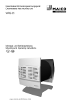
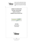
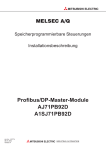
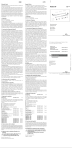
Thermostat TH 10 Montage- und Betriebsanleitung Mounting and Operating instructions D GB www.maico-v entilatoren.com D Thermostat TH 10 1. Lieferumfang Raumthermostat TH 10 mit Temperatursensor und 2 m Anschlussleitung (fertig verdrahtet), Montage- und Betriebsanleitung. 2. Verwendete Symbole 2.1 Warnsymbole GEFAHR ACHTUNG Lebensgefahr! Eine Nichtbeachtung kann zum Tod oder zu schweren Körperverletzungen führen. Sachschäden! Eine Nichtbeachtung kann zu Sachschäden führen. 2.2 Sonstige Symbole ● ● Aufzählungssymbol: Liste mit wichtigen Informationen zum jeweiligen Thema. Handlungssymbol: Liste mit durchzuführenden Tätigkeiten. Führen Sie die angegebenen Anweisungen der Reihe nach durch. 3. Produktinformationen 3.1 Geräteübersicht 1 2 3 4 5 6 7 Gehäuseunterteil LED Schaltzustand des Relais Steckbrücke Heizen/Kühlen Potentiometer Schaltdifferenz Anschlussklemme PG-Verschraubung Temperatursensor mit Anschlussleitung, 2 m lang 8 Drehknopfwelle 9 Abdeckung 10 Drehknopf Solltemperatur 2 3.2 Bestimmungsgemäße Verwendung ● Thermostat zur Steuerung von Ventilatoren in Abhängigkeit der Lufttemperatur. ● Zum Ein- und Ausschalten eines oder mehrerer Ventilatoren mit einer Maximalbelastung von 4 A (induktiv) und 10 A (ohmsche Last). ● Betrieb in Betriebsart Heizen oder Kühlen. Je nach Betriebsart schalten die Ventilatoren bei unter den Sollwert absinkender oder steigender Lufttemperatur ein, bis die Solltemperatur erreicht ist. ● Zur Wand-Aufputzinstallation in Gebäuden. ● Solltemperatur außen per Drehknopf, Betriebsart und Schaltdifferenz im Geräteinneren einstellbar. Impressum © Maico Elektroapparate-Fabrik GmbH. Originalanleitung. Druckfehler, Irrtümer und technische Änderungen vorbehalten. D ● im Außenbereich. ● mit dem Temperatursensor direkt über einem Heizkörper oder im Bereich eines Lufteinlasses (Tellerventil, Innengitter). ● Montage, elektrischer Anschluss und Reparaturen nur durch Elektrofachkräfte zulässig. ● Gerät nur an einer fest verlegten elektrischen Installation anschließen. Vorrichtung zur Trennung vom Netz mit mind. 3 mm Kontaktöffnung je Pol erforderlich. ● Gerät nur mit auf Typenschild angegebener Spannung und Frequenz betreiben. ● Keine Veränderungen am Gerät vornehmen. ● Gerät nie ohne Abdeckung [9] betreiben 4. Technische Daten 6.2 Sicheres und korrektes Verhalten für den Betrieb 3.3 Vorhersehbare Fehlanwendungen Maico haftet nicht für Schäden durch bestimmungswidrigen Gebrauch. Gerät auf keinen Fall einsetzen: ● in der Nähe von brennbaren Materialien, Flüssigkeiten oder Gasen. ● in explosionsfähiger Atmosphäre. Bemessungsspannung Netzfrequenz Schutzart Schutzklasse Maximalbelastung (induktive Last) Maximalbelastung (ohmsche Last) Schaltdifferenz Funkentstört nach EN 55011 Gewicht Abmessung (B x H x T) 230 V 50/60 Hz IP 54 II 4A 10 A 0,2 … 5 K VDE 0875 Störgrad N 0,4 kg 125 x 110 x 69 mm 5. Umgebungsbedingungen und Grenzen für den Betrieb ● Zulässige Umgebungstemperatur max. 50 °C ● Temperatur-Einstellbereich -10...+30 °C 6. Grundlegende Sicherheitshinweise 6.1 Allgemeine Sicherheitshinweise ● Sicherheitshinweise vor Inbetriebnahme aufmerksam durchlesen. ● Anleitung aufbewahren. ● Das Gerät darf nicht als Spielzeug verwendet werden. Das Gerät ist nicht dafür bestimmt, durch Menschen benutzt zu werden, deren physische, sensorische oder geistige Fähigkeiten nicht genügen, die Sicherheitshinweise dieser Anleitung zu verstehen und umzusetzen. Diese Einschränkung bezieht sich auch auf Kinder. Das Gerät kann dennoch von diesen Menschen gefahrlos benutzt werden, sofern sie von einer für ihre Sicherheit zuständige Person beaufsichtigt oder in geeigneter Weise unterwiesen werden. 7. Montagevorbereitungen ● Gerät nur auf trockenem, ebenen Untergrund montieren. ACHTUNG Fehlerhafte Messwerte durch ungeeigneten Montageort. Temperatursensor so montieren, dass die Raumtemperatur ohne Störeinflüsse erfasst werden kann. der Sensor keiner direkten Sonneneinstrahlung ausgesetzt ist. der Sensor sich nicht im Bereich von Zugluft, heißer oder kalter Luft (Herd, Heizkörper, Kühlschrank) befindet. der Sensor nicht in Baueinheit mit anderen wärmeerzeugenden Geräten verwendet wird (Dimmer). 3 D 8. Montage, Elektrischer Anschluss GEFAHR ACHTUNG Lebensgefahr durch Stromschlag! Netzsicherung ausschalten! Warnschild gegen versehentliches Wiedereinschalten anbringen. Kurzschluss durch Nässe bei nicht ordnungsgemäßer Einführung der Anschlussleitungen in das Gehäuse! Anschlussleitungen durch die PG-Verschraubungen in das Gehäuse führen. Darauf achten, dass die Gummidichtungen die Leitungen dicht umschließen. Drehknopf [10] abziehen, die 4 Schrauben lösen und Abdeckung [9] abnehmen. Gehäuseunterteil [1] mit 4 Schrauben an der Wand befestigen ( Pfeile, Kap. 3.1). Geeignetes Befestigungsmaterial ist bauseitig bereitzustellen. Mit Steckbrücke [3] die Betriebsart Heizen oder Kühlen einstellen (Werkseinstellung Heizen). Mit Potentiometer [4] die Schaltdifferenz einstellen (Einstellbereich 0,2…5 K). Anschlussleitungen durch die PG-Verschraubungen in das Gehäuse führen und Leitungen an Anschlussklemme [5] gemäß Schaltbild verdrahten. Abdeckung [9] auf das Gehäuseunterteil [1] aufsetzen, mit den 4 Schrauben verschrauben und Drehknopf [10] aufstecken. Abdeckung [9] lagegerecht aufsetzen. Darauf achten, dass Welle [8] nicht beschädigt wird. Netzsicherung einschalten. i Ventilator(en) gemäß deren Betriebsanleitungen installieren. 8.1 Inbetriebnahme Übereinstimmung mit den technischen Daten kontrollieren, siehe Typenschild. 4 Solltemperatur mit Drehknopf [10] einstellen. Funktionstest durchführen. Eine Überprüfung des Relais-Schaltzustandes ist mit LED [2] möglich. Die LED leuchtet bei angezogenem Relais (Klemme 4 und 5 geschlossen). i 9. Instandhaltung Das Gerät ist wartungsfrei. 10. Demontage Lebensgefahr, Gerät steht unter Spannung! GEFAHR Netzsicherung ausschalten! Die Demontage ist nur durch Elektrofachkräfte zulässig! 11. Entsorgung Entsorgen Sie das Gerät nach Ablauf seiner Lebensdauer nach den in Ihrem Land geltenden Bestimmungen. Nicht in den Restmüll ! Das Gerät enthält teils wiederverwertbare Stoffe, teils Substanzen, die nicht in den Restmüll gelangen dürfen. i 12. Schaltbild GB Thermostat TH 10 1. Scope of delivery TH 10 Room thermostat with temperature sensor and 2 m connection cable (fully wired), Mounting and Operating Instructions. 2. Symbols used 2.1 Warning symbols DANGER NOTICE Danger to life. Non-observance can lead to death or serious bodily injuries. Damage to property Non-observance can lead to damage to property. 2.2 Other symbols ● ● List symbol: List with important information about the corresponding subject. Action symbol: List of work to be carried out. Follow the instructions given in the order stated. 3. Product information 3.1 Equipment overview 1 2 3 4 5 6 7 Housing lower part Relay switching state LED Heating/cooling plug jumper Differential gap potentiometer Connecting terminal PG screw connection Temperature sensor with 2 m connection cable 8 Rotary knob shaft 9 Cover 10 Setpoint temperature rotary knob 3.2 Intended use ● Thermostat for controlling fans depending on the air temperature. ● For switching one or more fans with a maximum load of 4 A (inductive) and 10 A (ohmic load) on and off. ● Can be operated in heating or cooling mode. Depending on the operating mode, the fans switch on if the air temperature drops below or above preset levels and run until the setpoint temperature is reached again. ● For surface wall mounting in buildings. ● Setpoint temperature can be set with an external rotary knob. The operating mode and differential gap are set inside the unit. Acknowledgements © Maico Elektroapparate-Fabrik GmbH. Original instructions. We are not responsible for mistakes or printing errors and retain the right to make technical modifications without giving prior notice. 5 GB 3.3 Predictable misuses Maico is not liable for damages caused by use contrary to the intended purpose. The unit should not be used: ● Close to flammable materials, liquids or gases. ● In potentially explosive atmospheres ● Outdoors ● With the temperature sensor located directly above a heater or in the area of an air inlet (disk valve, internal grille). 4. Technical data Rated voltage Power frequency Degree of protection Protection class Maximum load (inductive load) Maximum load (ohmic load) Differential gap Interference suppression in accordance with EN 55011 Weight Dimensions (W x H x D) 230 V 50 / 60 Hz IP 54 II 4A ● Installation, electrical connections and repairs only permitted when carried out by trained specialists. ● Only connect the unit to a permanent electrical installation. Fixture for disconnecting from mains, with at least 3 mm contact opening needed per pole. ● The unit may only be operated using the voltage and frequency shown on the rating plate. ● Do not make any modifications to the fan unit. ● Never operate unit without the cover [9] in place. 6.2 Safe and correct practices during operation 0.2 … 5 K VDE 0875 Interference level N The unit is not intended to be used by people whose physical, sensory or mental capabilities are not sufficient for them to understand and put into practice the safety information provided in these instructions. This limitation also applies to children. The unit may however be safely used by such persons if they are supervised by someone responsible for their safety or if they are instructed in a suitable way. 0.4 kg 125 x 110 x 69 mm 7. Installation preparations 10 A ● Only install unit onto a dry, level surface. 5. Environmental conditions and operating limits ● Permitted max. ambient temperature: 50° C ● Temperature setting range -10...+30° C 6. Essential safety instructions 6.1 General safety instructions ● Read the safety instructions through carefully before commissioning. ● Keep the instructions. ● The unit must not be used as a toy. 6 NOTICE Incorrect measured values can result from unsuitable installation location! Install the temperature sensor such that The room temperature can be recorded without any disturbing influences. It is not directly exposed to direct sunlight. It is not in an area prone to draughts, hot or cold air, e.g. near stove, fridge, radiator, etc. It is not used in a unit with other heat-generating devices, e.g. a dimmer switch. GB 8. Installation, Electrical connection Danger to life from electric shock DANGER Switch the mains fuse off. Position a warning notice to avoid the unit being accidentally switched back on. Danger of short-circuits caused NOTICE by damp if the connection cable is not inserted in the housing correctly. Feed the connection cables into the housing through the PG screw-connections. Ensure that the rubber seals tightly surround the cables. Pull off the rotary knob [10], loosen the 4 screws and remove the cover [9]. Fix the housing lower part [1] to the wall with four screws ( arrow, Chapter 3.1). Suitable mounting material is to be supplied by the customer. Set operating mode to heating or cooling with plug jumper [3] (factory setting heating). Set the differential gap with the potentiometer [4] (setting range 0.2...5 K). Feed the connection cables into the housing through the PG screw-connections and wire the cables to the connecting terminal [5] according to the wiring diagram. Carry out a function test. The switching state of the relay can be checked by reference to LED [2]. The LED lights up if the relay is energised (terminals 4 and 5 closed). i 9. Maintenance The unit is maintenance-free. 10. Dismantling Danger to life. Unit is powered up. DANGER Switch the mains fuse off. Dismantling should only be carried out by a trained electrician. 11. Disposal Dispose of the unit once it has reached the end of its working life according to the regulations valid where you are. Do not dispose of it in domestic waste! The unit contains in part material that can be recycled and in part substances that should not end up as domestic waste. i 12. Wiring diagram Locate the cover [9] onto the housing lower part [1], screw it into place with the 4 screws and replace the rotary knob [10]. i Position the cover [9] correctly. Make sure that the shaft [8] is not damaged. Switch the mains fuse on. Install the fan(s) in accordance with their operating instructions. 8.1 Start-up Check that the technical data has been adhered to, by reference to the rating plate. Set the setpoint temperature using the rotary knob [10]. 7 09.11_Es Maico Elektroapparate-Fabrik GmbH • Steinbeisstr. 20 • 78056 Villingen-Schwenningen • Germany • Service +49 7720 694 447 • [email protected] 0185.0884.0001_RLF.3_09.11_DSW 8