1
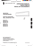
Installation and Operating Instructions
Split Air Conditioner for Wall Mounting
KSS 2508 AIV
KSS 3508 AIV
KSS 4508 AIV
Technical data ............................................................................................................................. 2
Energy efficiency ......................................................................................................................... 3
Checklist ...................................................................................................................................... 4
Refrigeration plan ........................................................................................................................ 4
Safety regulations ........................................................................................................................ 5
Device construction ..................................................................................................................... 6
Installation instructions ................................................................................................................ 7
Scope of supply ........................................................................................................................... 7
Minimum clearances.................................................................................................................... 8
Assembling the indoor unit .......................................................................................................... 9
Assembling the outdoor unit ...................................................................................................... 10
Refrigerant pipes ....................................................................................................................... 11
Connecting the refrigerant pipes on the outdoor unit ................................................................. 12
Electrical Connection ................................................................................................................. 13
Start-up...................................................................................................................................... 13
Important notes on operation..................................................................................................... 14
Circuit diagram........................................................................................................................... 15
Operation................................................................................................................................... 18
Cleaning and maintenance ........................................................................................................ 21
Faults......................................................................................................................................... 22
Warranty, after-sales service ..................................................................................................... 23
1
Technical data
Split room conditioners
KSS 2508 AIV
KSS 3508 AIV
KSS 4508 AIV
Indoor unit
KSS 2508 AIV I
KSS 3508 AIV I
KSS 4508 AIV I
Outdoor unit
KSS 2508 AIV A
KSS 3508 AIV A
KSS 4508 AIV A
kW
2.50 / 2.70
3.50 / 3.85
4.50 / 6.00
m³/h
450
550
800
Cooling capacity / heat output
1)
Air volumes, indoor unit
1/N/PE ∼230 V
Connection voltage
Nominal power consumption for cooling / heating
kW
0.73 / 0.85
1.16 / 1.27
1.58 / 2.05
Sound power level, outdoor / indoor unit (approx.)
db(A)
53 / 40
55 / 42
56 / 45
Net weight outdoor / indoor unit
kg
40 / 8.5
45 / 11
52 / 20
Dimensions, outdoor unit (W x H x D)
mm
830 x 540 x 320
830 x 540 x 320
914 x 685 x 384
Dimensions, indoor unit (W x H x D)
mm
770 x 250 x 180
830 x 285 x 189
1020 x 319 x 234
Condensate hose extension, indoor unit Required
inner hose diameter
mm
17
Height difference indoor unit - outdoor
unitmaximum
m
10
Length of refrigerant pipe, maximum
m
20
Refrigerant
R 410A
Temperature range, cooling
Indoor unit
(adjustable range)
Upper operating limit +33 °C / lower operating limit +18 °C
Outdoor unit (fixed-setpoint conditions)
Upper operating limit +43 °C / lower operating limit -10 °C
Temperature range, heating
Indoor unit
(adjustable range)
Upper operating limit +30 °C / lower operating limit +16 °C
Outdoor unit (fixed-setpoint conditions)
Length of plug cable, indoor unit
Upper operating limit +43 °C / lower operating limit -15 °C
m
1,5
Energy efficiency class cooling
Energy efficiency value (cooling/heating)
A
B
C
3.42 / 2.64
3.02 / 2.73
2.93 / 2.85
Special accessories refrigerant pipe
consisting of an insulated suction and pressure pipe pre-filled with refrigerant and with coupling and electrical connecting
cable.
Pre-filled refrigerant pipes, length 2 m
KMSL 1412-2 AIV
Assembly accessories
consisting of 2 brackets with dampeners for wall mounting of outdoor unit
Wall bracket
WKS 357
Condensate pump accessory
consisting of float-type switch and separate pump
Condensate pump
KSI 3100
Refrigerant pipes may be joined to extend them.
For refrigerant pipes longer than 8 metres, an on-site extension by the refrigeration technician is recommended.
2
Energy efficiency
Energy
Room air conditioner
Manufacturer:
Outdoor unit
Indoor unit
Dimplex
Dimplex
Dimplex
KSS 2508 AIV A
KSS 3508 AIV A
KSS 4508 AIV A
KSS 2508 AIV I
KSS 3508 AIV I
KSS 4508 AIV I
Low energy consumption
A
B
C
High energy consumption
Annual energy consumption
kWh in cooling mode
365
579
780
2.50
3.42
3.50
3.02
4.50
2.93
-
Yes
Yes Yes
-
Yes
Yes
Yes
kW
2.70
E
3.85
E
6.00
D
(Actual consumption depends on
usage of the device and cooling
conditions)
Cooling capacity
Energy efficiency value
kW
At full load (the higher the better)
Type
Cooling function only
Cooling function / heating function
Air cooling
Water cooling
Heat output
Energy efficiency class
of heating function
A: Low energy consumption
G: High energy consumption
Noise
3
Data for
KSS 4508 AIV
Standard EN 14511
Room air conditioner
Energy Labelling Directive 2002/31/EC
Data for
KSS 3508 AIV
The brochures include a data sheet
with further information on the devices
Data for
KSS 2508 AIV
dB(A) re 1 pW
Checklist
•
Has a calculation of the cooling load been made?
•
Is the cooling capacity of the device sufficient for the room to be cooled?
•
Are the operating limits sufficient for the purpose for which the air conditioner is intended?
•
Are the walls or the foundation for the installation of the outdoor unit strong enough?
•
The indoor unit should be installed in a position where it ensures uniform cooling.
•
Minimum clearances must be observed.
•
Planning the installation of the outdoor unit:
consider noise emission and free air circulation,
avoid direct sunlight,
ensure unimpeded access to the component,
installation at locations without access by general public.
•
Is a wall bracket required for the outdoor unit?
•
Plan the power cable and connection; ensure adequate fuse protection.
•
Check the maximum length and feasibility of the refrigerant pipes.
•
Refrigerant pipes should be as straight and short as possible.
•
When routing the refrigerant pipes, it is essential to maintain a bend radius of 3.5 x pipe diameter.
•
Excess piping should be wound up at a downward angle to the outdoor unit
in order to avoid displacement of refrigerant oil.
•
Take the height difference between indoor and outdoor unit into account.
•
If the outdoor unit is installed higher than the indoor unit: provide an oil siphon every 3 vertical meters.
•
Plan condensate drainage. If the condensate hose on the indoor unit cannot be routed with a downward slope,
a condensate pump must be provided. The condensate is always formed at the “ cold” side of the air conditioner;
this means for cooling in the inner component and for heating in the outdoor unit.
•
Is an approval by the local utility company required?
Refrigeration plan
Condenser
Capillary
Filter dryer
Filter dryer
4-way valve
Coupling
Evaporator
Compressor
Damper
Collector
Coupling
4
Safety regulations
General
•
Please read these installation and operating instructions carefully and fully before commencing installation! They contain
important information about the assembly, use and maintenance as well as safety instructions to be observed!
•
After unpacking the device, inspect it for any transport damage. In case of doubt, do not put the device into use but have it
examined by a qualified technician.
•
Before connecting the device, please ensure that the mains supply network corresponds to that required by the device
according to the type plate data. Observe the utility company's local connection conditions.
•
The room air conditioner must not be operated in rooms where highly inflammable substances are used (e.g. solvents, etc.).
•
The device must be unplugged from the mains before any cleaning or maintenance work is carried out.
•
This device may be used only for the purpose for which it was manufactured, i.e. for heating, cooling, dehumidification and
air recirculation of rooms. All other purposes are not those for which it was intended and must therefore be regarded as
hazardous.
•
In the case of a fault and/or functional defect, please switch the device off (disconnect from the mains). Do not try to repair
the device yourself. Necessary repairs must be carried out by the after-sales service.
•
The power supply cable may only be replaced by a qualified electrician.
•
The manufacturer is not liable for damage caused by improper or incorrect use or the incorrect installation of the device.
Device-specific
•
The device must be installed according to the manufacturer’s specifications. Incorrect setup can cause injury to persons or
animals and damage to property.
•
Where possible, the outdoor unit is to be installed in such a way that it is not exposed to direct sunlight.
•
The inlet and outlet vents of the air conditioner must not be covered or blocked.
•
Do not insert any objects into the device openings.
•
Disconnect the air conditioner from the power supply if the device is not operated for a longer period of time.
•
The air conditioner should be inspected at regular intervals (e.g. before the cooling season).
•
The condensate which collects in or runs out of the air conditioner should not be drunk.
•
Do not operate the room air conditioner without an air filter.
•
The air filters should be cleaned at regular intervals (depending on user and room).
•
Do not place any objects on top of the air conditioner.
•
The indoor unit of the air conditioner may be operated in dry rooms only.
•
Do not pour or spray any liquids onto or into the air conditioner.
•
Do not use hairsprays, solvents or similar materials (aerosols) in the vicinity of the air conditioner.
•
The air conditioner should be switched off immediately in the case of a fault (e.g. if smoke is created or an unusual smell is
noticed). Disconnect the device from the power supply (switch off the fuse or pull out the plug) and contact an authorised
after-sales service.
•
Keep persons with impaired health, small children and pets away from the direct air current since this may have a
detrimental effect on their health.
•
The device may be assembled and disassembled only by a qualified technician.
5
Device construction
1
2
3
4
5
6
7
8
9
10
11
Indoor unit
Air inlet
Airflow fins (for adjustable air outlet direction)
Air outlet
Signal receiver (of the remote control) with indicator lamps
Mains connection cable on indoor unit
Outdoor unit
Air inlet
Air outlet
Connection lines indoor unit - outdoor unit
Condensate outflow hose
6
Installation instructions
Before choosing an air conditioner, we recommend carrying out a cooling load calculation according to the standard, or on the
basis of a relevant standard. Forms for cooling load calculation complete with instructions can be obtained from the
manufacturer or wholesaler or on the Internet at www.dimplex.de
Indoor or outdoor units, which are not installed according to instructions, may cause a reduction or loss of warranty in case of
repair!
Choosing the installation location
It is very important to install split devices in suitable locations as it is difficult, and thus expensive, to move them after installation.
If possible, decide on the installation location in agreement with the final customer. The installation site must be suitable for
bearing the weight and the operational vibration of the indoor or outdoor unit on a permanent basis.
Notes on the installation of the indoor unit
The circulating air should flow through the whole of the room to be cooled.
The flow of cold air should not be directed at persons or their place of work.
The condensation formed during cooling must be drained off without impairing functioning. If the condensate can only be led off
upwards or without a downward slope, then the installation of a condensate pump is necessary.
The component may not be installed in rooms subject to high humidity in which the device is in contact with moisture or water.
The device may not be installed in rooms in which oil vapour is emitted or could be emitted.
Notes on the installation of the outdoor unit
The outdoor unit should be installed in a place where it will not become soiled.
When there is a danger of condensate freezing (heating operation when outside temperatures are low), the condensate drain
stubs should be removed and additional insulation be provided for the drainage area. Freezing condensate (e.g. the formation of
ice on the heat exchanger) can impede the fan function of the outdoor unit.
The outdoor unit must be installed in compliance with the regulations regarding the assessment of operational noise in the
neighbourhood. In particular, a suitable distance from bedrooms and similar rooms should be maintained.
The device may not be installed in areas of aggressive air!
Scope of supply
Please check that the delivery is complete and that the devices are undamaged.
The scope of supply includes:
•
Split air conditioner consisting of indoor and outdoor unit (2 packaging units in case of complete order),
•
Mounting plate for wall mounting of the indoor unit, slotted into it (incl. screws)
•
Remote control (incl. 2 batteries),
•
Condensate drain plug for draining condensate in the outdoor unit,
•
Control line with connection plug routed in the refrigerant pipe,
•
Mains connection cable,
•
Installation and operating instructions
7
Minimum clearances
All dimensions in mm
8
Assembling the indoor unit
Installation instructions
Bends in the refrigerant pipes may not be positioned
immediately before or after refrigerant couplings!
If it does not matter whether the pipes are visible in the
room, they can be led out of the side of the indoor unit to
the left and routed through the wall at some other suitable
location.
Perforated sections are provided accordingly in the housing
area of the indoor unit.
Indoor unit
Wall
Downward slope
Wall mounting
Drilling through the wall
One opening in the wall with a minimum diameter of 80
mm is necessary for the passage of the condensation hose
as well as the refrigerant and electrical lines from the indoor
unit to the outdoor unit.
The opening must slope downward at an angle of about 5°
toward the outside wall to allow the condensate to drain.
Insert a bushing into the wall opening to prevent damage to
the lines!
The end of the condensate hose may not be stand in the
water.
min. 5°
The diagram below shows the recommended position for the wall opening depending on the minimum distances.
150
Front view
150
150
B
Ø=80
60
80
A
2000
KSS 2508 KSS 3508 KSS 4508
Maß A
770
830
1020
Maß B
250
285
310
Installation
The mounting plate for the indoor unit must be aligned horizontally and mounted while observing the minimum clearances.
Route the lines through the wall opening.
Engage the indoor unit in the upper profiles of the mounting plate and swivel it downward
until the indoor unit engages.
9
Assembling the outdoor unit
Mount the outside component on a suitable support or wall with adequate load capacity.
The wall bracket WKS 357 is available as an accessory.
•
The inflow and outflow of air must be unimpeded.
•
An air short circuit must be avoided.
•
Minimum clearances must be observed.
•
Distances to bedrooms and third-party rooms should be selected as large as possible to avoid annoying noise.
See “ Technical Data” for sound power levels.
Top view of outdoor unit
E
C
D
Distances between the drilling holes for mounting the outdoor unit. All dimensions in mm.
Type
Dim. A
Dim. B
Dim. C
Dim. D
Dim. E
KSS 2508 AIV
KSS 3508 AIV
KSS 4508 AIV
288
288
342
320
320
384
540
540
550
760
760
844
70
70
70
Condensate drainage in the outdoor unit
During heating operation there is a formation of condensate which must be drained.
There is a hole (diam. 25) for condensate drainage in the base plate of the outdoor unit into which the condensate drainage plug
supplied can be inserted.
If the installation situation permits this, the condensate formed can drip down from the bottom side of the outdoor unit; otherwise
drainage must be provided by connecting a hose.
Caution!
•
If possible, the drain house should not be fixed.
•
If a condensate hose is is installed, it must always slope downwards.
The condensate may possibly freeze when heating below temperatures of +4 °C.
This may block the fan.
If temperatures below +4°C are to be expected at the condensate outlet during heating operation, appropriate measures, e.g.
insulation (insulation of the base of the casing and the condensate drainage area) should be taken.
Sealing the wall opening
This is not done until the outdoor unit has been installed and all necessary connections between the indoor and the outdoor unit
have been made.
The wall openings must be closed in a correct manner.
In the case of fire protection walls, the relevant regulations must be complied with.
10
Refrigerant pipes
Technical information
The refrigerant pipes, the indoor and outdoor units are pre-filled with refrigerant R410A.
The refrigerant R410A belongs to group 1 of refrigerants according to VBG 20. It is non-combustible and does not cause serious
damage to human health.
The following must be observed when installing refrigerant pipes:
•
•
•
•
•
•
•
The refrigerant should not come into contact with the eyes (if necessary, protective goggles should be worn).
Refrigerants can cause frostbite in contact with the skin (if necessary, suitable protective clothing, such as gloves, should
be worn).
Contact with open flames or very hot surfaces can cause the refrigerant to decompose and give off poisonous gases.
Caution! Do not smoke while disconnecting or closing refrigerant pipes!
Do not inhale the refrigerant!
Refrigerant is heavier than air; if it leaks it collects on the ground.
In high concentrations it can cause a lack of oxygen. There is a danger of suffocation.
A defective refrigerant pipe must be properly disposed of by a qualified specialist company or the authorised customer service.
Installation
If possible, the refrigerant pipes should be routed in suitable conduits (e.g. conduits for electrical installations) which allow the
pipes to be replaced in case of replacement or repair.
•
Subsequently wrapping the refrigerant pipes with cloth adhesive tape protects the line insulation from damages due to UV
rays and mechanical impact (rubbing against walls, bird bites). As an additional benefit, it makes the installed pipes more
rigid - thereby reducing vibration.
•
The pipes may not have more than three bends in succession and not more than 12 bends over their entire length.
•
The number of bends should be kept to a minimum.
•
The radius of the bends must be at least 3.5 times the external diameter.
•
Install the pipes with a downward slope toward the outdoor unit or wind them up to prevent residues of refrigerant oil.
If the height difference between indoor and outdoor unit is greater than 3 metres, a siphon-type bend must be created every 3
metres of height difference. For example, 2 bends at 6 metre height, 3 bends at 9 metre height, etc.
Outdoor unit installed higher
than the indoor unit
Refrigerant flow
Provide a siphon every 3
vertical meters.
Oil separator
11
Connecting the refrigerant pipes on the outdoor unit
Important information
•
Preventing dirt and moisture from entering the system is imperative; clean all connections with a dry cloth, if necessary.
•
The coupling connections may be loosened or opened again after connecting them, if required. Avoid frequent opening.
•
Repairs must only be carried out by an authorised after-sales service.
1
1
2
2
Remove dust caps/ transport protection. Pull back the locking ring.
Push on the refrigerant pipe coupling.
A
3
3
4
4
Push the locking ring forward again and close the fastening tab.
Secure the connection with a screw (A) to prevent unintentional loosening.
Insulate the refrigerant connections to prevent condensate formation.
12
Electrical Connection
Electrical connection on the outdoor unit
-
Remove the cover,
open the strain relief clamp,
plug in the plug,
fasten the grounding wire to the mounting plate,
fasten the electrical cable to the strain relief clamp,
attach the cover again.
Electrical connection on the indoor unit
The power supply of the indoor unit and the outdoor unit is
done via the pre-installed connecting cable with power plug on
the indoor unit.
•
•
•
•
•
Operation only with 230 V AC!
Observe the safety and connecting conditions!
Provide separate fuse protection for circuit!
Connection and repair only by a qualified specialist!
Provide a disconnecting device in the permanently
installed wiring with at least 3 mm conctact opening at
each pole (e.g. automatic circuit breaker)
Electrical connection on the outdoor unit
Start-up
Check the following before start-up:
•
Are all refrigerant pipes and connections tight (e.g. using a leak test spray)?
•
Has the electrical installation been carried out correctly?
•
Have the indoor and outdoor units been installed in a secure and vibration-proof manner?
•
Have the refrigerant pipes been routed correctly?
•
Has the max. permitted length not been exceeded?
•
Have the coupling elements on the outdoor unit been insulated?
•
Have all installation residues or contamination been removed from the indoor and outdoor unit?
•
Have the air filter and condensate drainage pipes been installed properly?
•
Were functioning batteries correctly placed in the remote control?
Function test
•
Plug in the device and turn on the circuit breaker. Operate the “ ON/OFF” button of the remote control.
•
Operate the “ MODE” button of the remote control.
•
Check all operating modes (cooling, circulation, heating, dehumidifying) if the ambient temperatures
permit this (application limits).
•
Certain start-up times or pauses depend on the function when switching from one operating mode to another.
If the device cannot be switched on using the remote control:
−
−
Open the front of the indoor unit.
Operate the AUTO/STOP button (at the right upper corner).
Checking the function of the remote control must now be possible.
13
Information on the efficient use of the device
Important notes on operation
•
•
Use the air conditioner only for the following purposes:
•
for room cooling,
•
for room heating,
•
for room dehumidification,
•
to circulate the air in the room.
•
Keep windows and doors closed during air conditioning!
Select the suitable setting of the airflow direction
direct the airflow downward in heating operation,
direct the airflow upward in cooling operation.
In cooling operation, set the room temperature no more
than 5° below the outside temperature.
Heating operation
The device operates with heat pump switching. Heat is
extracted from the outside air, then led to the indoor unit and
released in the room.
The heat output diminishes as the temperature of the
outside air drops!
If the device does not provide sufficient heat for the room,
we recommend operating it in combination with another
heater.
Heat pump air conditioners circulate the warm air in order to
heat the entire room. It therefore takes some time until the
entire room is warm (also depends on the external
temperature and the heating requirement).
Permissible temperature and humidity ranges
Temperature range of outdoor unit* -10 °C to
+43 °C
Humidity range of outdoor unit
approx. 40 to 80 %
Cooling
Temperature range of indoor unit* +18 °C to
+33 °C
Humidity range of outdoor unit
approx. 40 to 80 %
Automatic de-icing
If the device is exposed to high humidity over
a long period, condensate may form and drip
down.
When external temperatures are low and air humidity is high,
heating operation can cause the formation of ice on the
outdoor unit - which reduces the heat output.
Temperature range of outdoor unit* -10 °C to
+43 °C
In this case, the device switches automatically to the “ De-
Humidity range of outdoor unit
approx. 40 to 80 %
frost” mode for 10 – 15 minutes, heating is interrupted and
the fans cease to operate.
Heating
Temperature too high
If the device is exposed to high humidity over
a long period, condensate may form and drip
down.
Temperature range of indoor unit* +18 °C to
+33 °C
When, in heating operation, both room and external
temperatures are too high, the fan of the outdoor unit may
switch off periodically (protective function).
Humidity range of outdoor unit
approx. 40 to 80 %
Power disruption/ power cuts
*
If the device is exposed to higher temperatures, the
automatic safety mechanism may be triggered and
operation may be interrupted.
If the device is exposed to lower temperatures, ice
may form on the heat exchanger, which can cause water
(condensate) to run out or lead to other malfunctions.
After a power cut the devices restart operation in the
operating mode last set (with the temperature setting last
stored). This occurs in cooling and dehumidifying mode with
a starting delay of approx. 3 min.
In heating operation this restart phase can last up to 17
minutes.
The alignment of the airflow fins (SWING) may need to be
reset after a power disruption.
14
Circuit diagram
KSS 2508
Indoor unit
Outdoor unit
15
Circuit diagram
KSS 3508
Indoor unit
Outdoor unit
16
Circuit diagram
KSS 4508
Indoor unit
Outdoor unit
17
Operation
Operating display on the remote control
Function buttons of remote control
1
2
3
4
5
6
7
8
9
10
11
12
13
14
15
16
17
18
19
20
21
22
23
24
25
26
Remote control
Display window
Select operating mode
Automatic / Cooling / Dehumidifying / Circulation /
Heating
Swing operation On/Off
Setting the current time
Setting the timer function - switch-off time
Setting the time - increasing the time
Deactivating the timer function
Setting the time - reducing the time
Timer function - setting the switch-on time
Sleep function On/Off
Fan level – Selecting the speed
Increasing the default room temperature
Decreasing the default room temperature
Operation On/Off
27
28
29
30
31
18
Fan speed is determined automatically
Fan on
Fan speed low / normal / high
Send - default is sent.
Dehumidifying operating mode
Heating operating mode
Sleep function set
Circulation operating mode
Swing operation ON display
Current time, set timer time
AM – time before noon
PM – time afternoon
ON – time timer On
OFF – time timer Off
Timer function activated
Room temperature default
Automatic operating mode
Cooling operating mode
Inserting the batteries in the remote control
Setting the fan speed
Remove the cover of the battery compartment.
The fan speed can be set at three levels. The fan speed is
set with the FAN (12) button.
Insert two “ 1.5 V MICRO AAA” batteries in the battery
compartment.
Observe the polarity (+/-) in the housing.
Replace the cover of the battery compartment.
The fan speed cannot be changed in the dehumidifying
operating mode.
Press the ON/OFF (15) button to switch on the device.
Press the FAN (12) button once or several times until the
desired fan speed (18) is set.
Note:
Insert new batteries if the display of the remote control is
weak or flickers or cannot be seen at all.
Cooling
Press the ON/OFF (15) button to switch on the device.
Press the MODE (3) button once or several times until the
Cooling (31) display appears.
The desired room temperature can be set with the TEMP+
(13) and TEMP- (14) buttons.
Setting range: 16-30 °C, setting increments: 1 °C.
Dehumidification
Press the ON/OFF (15) button to switch on the device.
Press the MODE (3) button once or several times until the
Dehumidification (20) display appears.
The desired room temperature can be set with the TEMP+
(13) and TEMP- (14) buttons.
Setting range: 16-30 °C, setting increments: 1 °C.
In the Dehumidification operating mode, the fan works only
at a low speed to achieve optimal dehumidification.
Circulation mode
Press the ON/OFF (15) button to switch on the device.
Press the MODE (3) button once or several times until the
Circulation mode (23) display appears.
The desired room temperature can be set with the TEMP+
(13) and TEMP- (14) buttons.
Setting range: 16-30 °C, setting increments: 1 °C.
Setting the time
Press the CLOCK (5) button.
The display (26) AM (before noon) or PM (afternoon)
flashes.
Set the current time with the TIME + (7) or TIME - (9)
buttons.
Briefly touching the buttons causes a change in 1-minute
increments.
Prolonged touch of the buttons causes a change in 10minute increments.
Heating
Press the ON/OFF (15) button to switch on the device.
Press the MODE (3) button once or several times until the
Heating (21) display appears.
Press the CLOCK (5) button to store the set time.
The desired room temperature can be set with the TEMP+
(13) and TEMP- (14) buttons.
Setting range: 16-30 °C, setting increments: 1 °C.
19
Automatic mode
Swing operation
Depending on the room temperature, the operating modes
COOLING and HEATING are determined automatically.
The temperature cannot be set manually.
Up – down air flow
The Swing operation can be turned on and off using the
SWING (4) button.
Furthermore, the air flow can be specified for a specific air
outlet direction.
Press the ON/OFF (15) button to switch on the device.
Press the MODE (3) button once or several times until the
AUTO (30) display appears.
Press the ON/OFF (15) button to switch on the device.
Press the SWING (4) button.
The SWING (24) display appears.
The direction of the air flow is continuously changed from
top to bottom and vice versa.
The Swing operation is switched off again by pressing the
SWING button once more.
The operating mode COOLING is selected automatically:
at temperatures of 25 °C or higher.
The operating mode HEATING is selected automatically:
at temperatures of 25 °C or lower.
Timer function
Left – right air flow
The horizontal air outlet direction is set manually.
The time-dependent operation of the air conditioner can be
programmed on the remote control.
Select the switch-on time
Press the T-ON (10) button – the ON (27) display flashes.
Set the current switch-on time with the TIME + (7) or TIME
- (9) buttons.
Press the T-ON (10) button once more to store the selected
switch-on time.
Select the switch-off time
Press the T-OFF (6) button – the OFF (27) display flashes.
Set the current switch-off time with the TIME + (7) or TIME
- (9) buttons.
Press the T-OFF (6) button once more to store the selected
switch-off time.
Adjusting the airflow fins
NOTE:
In the operating modes Cooling and Dehumidifying,
condensate can form on the airflow fins turned to the right
or left, and may possibly drip down. Use this setting,
therefore, only for a short time.
Delete timer settings
Press the CANCEL (8) button.
Special care must be taken when using the air conditioner
in rooms with infants, small children, elderly or sick persons
to prevent any danger to health.
Sleep function
To increase your comfort while sleeping at night.
Reduces the fan speed and controls the specified room
temperature values even more precisely.
This function is only available in the operating modes
Cooling (31), Dehumidifying (20) and Heating (21).
Press the ON/OFF (15) button to switch on the device.
Press the SLEEP (11) button - the Sleep function (22)
display appears.
20
Cleaning and maintenance
The device must be disconnected from the mains and
allowed to cool down before cleaning and maintenance.
Clean the surfaces of the casings with a soft damp cloth
and then dry them. Use only lukewarm water. No scouring
agents or polishes should be used.
Auxiliary filter
Remove the two auxiliary filters, if present, as well.
Cleaning the air filters
Soiled filters reduce the airflow and thus the efficiency of
the device. Soiled filters can also cause noise.
Both filters should be checked at the beginning of the
active period and cleaned as necessary.
The degree of soiling largely depends on the location and
operating conditions. More frequent cleaning may be
required.
Take hold of the front cover of the indoor unit on both sides
and flap it up until it clicks into an open position.
Clean the air filter with a vacuum cleaner.
If the filters are heavily soiled, they can also be cleaned
with a neutral cleaning solution.
The air filters must be completely dry before installing them
again.
Installation is done in the reverse order.
Push the filter slightly upward at one side until it
disengages from its locked position.
Fully remove the filter.
Repeat the procedure with the second filter.
21
Faults
In case of malfunction, stop the operation of the air conditioner immediately, deactivate the unit and disconnect from the mains.
Switch off the automatic circuit breaker in the manifold and pull of the mains plug, if necessary.
Contact the after-sales service.
You can detect possibly impaired function by a reduced output, smoke development, unusual odours, loud noises, increased
tripping of the fuse or unusual heat development.
However, before you contact the after-sales service, please use the list below to check whether this could be a normal
occurrence or a fault you can remedy yourself.
Type of fault
Possible causes
Device does not switch on immediately
If the device is switched off and then on again immediately, a safety function
prevents it operating for about 3 minutes (compressor safety function).
The same thing happens when disconnecting the air conditioner from the mains
and then switching it on again. Again the safety function prevents the operation of
the device for approx. 3 minutes.
A delay of up to 17 minutes can occur before the heating function starts or warm air
begins to circulate, e.g. when the operating mode is changed or there is a power
cut when in heating mode.
Noises
Noises caused by the flow of the refrigerant through the pipes can sometimes be
heard during operation. These noises tend to occur particularly during the first two
to three minutes after switching on or off.
Temperature fluctuations cause material expansion and contraction, which can also
produce noises.
Smells
The air emitted by the indoor unit may carry various smells already present in the
room, e.g. cooking smells, tobacco, new furniture, etc.). Because the airconditioned air is emitted at a higher speed, the smells can be perceived as more
intensive.
Emission of steam or vapour
Slight vapour formation may be visible at the device during cooling or
dehumidification. This is due to the sudden cooling of the existing room air by the
climatised air and is normally no longer perceivable after a few minutes.
Device is not working
Is it connected to the mains power supply?
Has a fuse blown?
Have the operating limits been exceeded?
Has a power cut occurred?
Are the batteries in the remote control working?
The device switches off or on
unintentionally
The timer function may possibly be activated.
The command entered on the remote
control is not executed
Depending on the operating mode selected, impractical functions cannot be
executed.
Inadequate cooling or heating
Do the air filters need cleaning?
Are the device’ s inlet and outlet vents covered or clogged with dirt?
Have additional sources of heat been switched on? (during cooling mode)
Are the room temperature settings appropriate?
Are the windows and doors in the room to be cooled or heated open?
Has the correct fan speed been set (air volume)?
Are larger window surfaces present during cooling operation through which direct
sunlight enters the room?
You may need to close the curtains, lower the blinds, etc.
22
Warranty, after-sales service
The following conditions, describing the requirements and scope of our warranty service, do not affect the warranty obligations
of the sales person from the sales contract with the end customer. We offer a warranty for the devices according to the following
conditions:
Based on the following conditions, we remedy defects of the device free of charge which can be proven to be due to material
and/or manufacturing defects if they are reported to us without delay upon being detected and within 24 months after delivery to
the first end customer. This period is 12 months when the device is used commercially. If the defect appears within 6 months
after delivery and a successful start-up (heat pumps for heating purposes and central room ventilation devices) by the
authorised after-sales service for complete systems, a material or manufacturing defect can be expected.
This device is only covered by this warranty if it was purchased by a company in one of the member states of the European
Union, it is operated in Germany when the defect occurs and warranty service can also be rendered in Germany.
The defects which we have recognised as being covered by warranty are remedied in that the defective parts are repaired free
of charge at our discretion or replaced by flawless parts. Exceptional costs of defect remedy due to the type or location of the
device's use or poor accessibility of the device are not covered by us. The end customer must ensure free access to the device.
Dismantled parts which we take back become our property. The warranty time for rework and spare parts ends with the
expiration of the original warranty period for the device. The warranty does not cover easily breakable parts which affect the
value or operational use of the device only insignificantly. The original purchase receipt with purchase or delivery data must
always be presented.
The warranty becomes void if the end customer or a third party did not comply with the applicable VDE regulations, the
stipulations of the local utility company or our installation and operating instructions as well as the information and integration
diagrams included in the project planning documents or if the our accessories required for proper functioning were not used.
The liability for the consequences of modifications and work activities performed improperly by the end customer or third party
becomes void. The warranty covers the device and the parts purchased from the supplier. Parts and devices not purchased by
the supplier and system defects due to parts not purchased from the supplier are not covered by warranty.
If the defect cannot be remedied or the repair is denied by us or unreasonably delayed, the manufacturer will either deliver a
replacement free of charge or reimburse the reduced value. In case of providing a replacement delivery, we reserve the right to
apply a reasonable usage for the time of usage incurred so far. Extended or other claims, especially those for compensation of
damages incurred outside of the device, are excluded unless liability is legally mandated. In case of liability according to article
478 of the German Civil Code (BGB), the liability of the supplier is limited to the lump-sum service fees constituting the
maximum amount.
An extension of the warranty to 36 months for heater heat pumps and central room ventilation devices from the date of start-up
but no longer than 38 months after delivery ex factory is granted under the following conditions: The prerequisite for accepting
the extended warranty is the chargeable start-up by the authorised after-sales service for complete systems with a start-up log
within an operating time (compressor runtime) of less than 150 hours. Defects noted in the start-up log must be remedied
immediately. This is the basis for the warranty. The start-up log shall be submitted to the address specified below within one
month after the start-up; the extension of the warranty period will be confirmed by this same address.
The start-up costs flat charge includes the actual start-up and the travel expenses. No liability is assumed for the proper
planning, dimensioning and execution of the overall system. Remedying system defects and waiting times are extra services.
The start-up costs flat charge for all heat pumps for heating purposes is currently € 340 net and € 400 net for central
ventilation systems, for each device, and is charged to the ordering party by the authorised after-sales service for complete
systems. Price adjustments are reserved.
In case of a situation requiring service, the authorised after-sales service for complete systems on site is notified who will quickly
remedy the problem. You can find out about the after-sales service for complete systems responsible for your area by
contacting the central service hotline of Glen Dimplex Deutschland GmbH.
Glen Dimplex Deutschland GmbH
Dimplex Division
After-sales service for complete systems
Am Goldenen Feld 18
95326 Kulmbach, Germany
E-mail address
Internet:
[email protected]
www.dimplex.de
Phone No.
+49 (0) 9221 709 562
Fax No. +49 (0) 9221 709 565
[email protected]
To process your order, we require the production number (E-Nr.) and the device’s production date (FD).
This information can be found on the type plate in the framed field.
23
Note on disposal
Do not dispose of the unit with general household waste. The device must be taken to a local waste disposal plant.
Glen Dimplex Deutschland GmbH
Am Goldenen Feld 18
D-95326 Kulmbach
Telephone: +49 (0) 9221 709 562
Fax: +49 (0) 9221 709 565
E-mail: [email protected]
24
Subject to technical changes
Internet: www.dimplex.de
kss08-gb_ba.doc 08/08/A