1
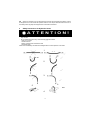
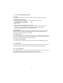
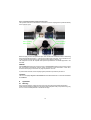
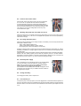
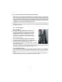
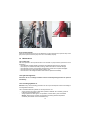
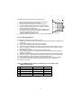
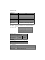
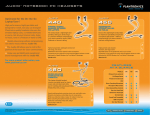
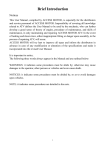
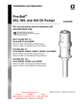
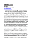
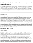
Operating Instructions
Rescue Tools
115001085 GB
Issue 10.2007
Battery Pump P 600 OB
2
8
7
1
6
5
4
3
1
2
3
4
5
6
7
8
Main switch
Indicator pin
Battery
Connection for charger cable
Connection for external power supply 24 V DC
Charge indication panel
Dump valve
Carry harness
1
Contents
page
1 Basic Operation and designated Use of the Machine
3
2 Organizational Methods
3
3 General Safety Instructions
3
4 Instructions for Maintenance and Service
4
5 Safety Instructions for Hydraulic Hoses
5
6 Intended Use
7
7 Description
7
8 Commissioning
9
9 Operation
10
10 Maintenance
13
11 Problems / Trouble Shooting
15
12 Repair
16
13 Battery
16
14 Technical Data
17
2
1
Basic operation and designated use of the machine
1.1
The machine has been built in accordance with state-of-the-art standards and the recognized
safety rules. Nevertheless, its use may constitute a risk to life and limb of the user or of third parties,
or cause damage to the machine and to other material property.
1.2
The machine must only be used in technically perfect condition in accordance with its
designated use and the instructions set out in the operation manual, and only by safety-conscious
persons who are fully aware of the risks involved in operating the machine. Any functional disorders,
especially those affecting the safety of the machine/plant, should therefore be rectified immediately!
1.3
The machine is exclusively designed for the use described in the operating manual. Using the
machine for purposes other than those mentioned in the manual, such as driving and controlling
other hydraulic systems, is considered contrary to its designated use. The manufacturer/supplier
cannot be held liable for any damage resulting from such use. The risk of such misuse lies entirely
with the user.
Operating the machine within the limits of its designated use also involves observing the instructions
set out in the operating manual and complying with the inspection and maintenance directives.
2
Organizational methods
2.1
The operating manual must always be at hand at the place of use of the machine!
2.2
In addition to the operating instructions, observe and instruct the user in all other generally
applicable legal and other mandatory regulations relevant to accident prevention and environmental
protection.
This also applies for wearing protective clothing, helmet with visor or goggles and protective gloves.
2.3
In order to avoid injuries, the machine must only be operated by a specially trained operator
who has undergone a safety training.
2.4
Observe all safety instructions and warnings attached to the machine. Make sure that safety
instructions and warnings attached to the machine are always complete and perfectly legible.
2.5
Never make any modifications, additions or conversions without the supplier’s approval.
2.6
For repairs only genuine LUKAS spare parts, accessories or system components must be
used.
2.7
Adhere to prescribed intervals or those specified in the operating manual for routine checks
and inspections.
2.8
Make sure to dispose properly of packing material and dismounted parts!
3
General safety instructions
3.1
In the event of malfunctions, stop the machine immediately and lock it. Have any defects
rectified immediately.
3.2
Before starting up or setting the machine in motion and during operation of the machine make
sure that nobody is at risk.
3
3.3
Before transporting the machine always check that the accessories have been safely stowed
away.
3.4
Make sure that there is enough lighting during work.
3.5
Avoid any operation that might be a risk to machine stability.
3.6
Check the machine at least after every operation for obvious damage and defects. Report any
changes (incl. changes in the machine’s working behaviour) to the competent organization /person
immediately. If necessary, stop the machine immediately and lock it. All lines, hoses and screwed
connections have to be checked for leaks and obvious damage. Repair damage immediately.
Splashed oil may cause injury and fire.
3.7
All safety equipment has to be checked for completeness and flawless condition:
- instruction markings and warning signs (safety instructions)
- check safety cover (e.g. motor-safety covers, heat protection etc.) if they are available and if
they are in good condition.
3.8
Working under loads is not allowed if they are only lifted by hydraulic cylinders. If the work is
indispensable sufficient mechanical supports are needed additionally.
3.9 The pump is filled with hydraulic fluid. Never swallow or breath in this fluid as this could be
dangerous to your health ! Avoid direct contact between the fluid and your skin !
Be aware that hydraulic fluid may cause negative effects to any kind of biologic systems.
4
Instructions for maintenance and service
4.1
For the execution of maintenance and service work, tools and workshop equipment adapted
to the task on hand are absolutely indispensable.
Work on the hydraulic system must be carried out only by personnel having special knowledge and
experience with hydraulic equipment.
4.2
Before putting into operation clean the machine, especially connections and threaded unions,
of any traces of oil, fuel or preservatives before carrying out maintenance/repair. Never use
aggressive detergents. Use lint-free cleaning rags and pay attention that the components are
meticulously clean during reassembling after repair.
4.3
During dismantling of machines it is necessary to collect the outrunning hydraulic liquids
completely, so that they cannot reach the ground. They have to be disposed properly according to
the instructions.
4.4
Always tighten any screwed and thread connections that have been loosened during
maintenance and repair. Observe the stipulated torques.
4.5
Work on the electrical system or equipment may only be carried out by a skilled electrician
himself or by specially instructed personnel under the control and supervision of such electrician and
in accordance with the applicable electrical engineering rules.
4.6
The electrical equipment of machines is to be inspected and checked at regular intervals.
Defects such as loose connections or scorched cables must be rectified immediately.
4.7
Aggressive material (acid, lye, solvent, vapour) can damage the machine. It is necessary to
clean the whole machine if it must be exceptionally operated under such conditions or gets into touch
with these materials. Additionally, the machine must be checked as described under 3.6.
4
4.8
Should you observe a loss of speed of the rescue tool during operation the battery must be
recharged. Do not continue with the operation until the motor stops. Otherwise there is the risk of
the battery becoming deep discharged which would reduce its lifetime.
5
Safety Instructions for Hydraulic Hoses
ATTENTION!
-
by no means the hose must be exposed to brake fluid as this fluid will destroy outer
layer of hose
- do not expose the hose to any of the following aggressive fluids:
• acid, lye or solvent
• alcohol and fuel
• battery and automatic transmission fluid
• phosphate ester
Clean hose immediately with water and detergent when it was exposed to such fluids.
1
2
3
6
5
Bild 2
4
5
5.1
-
-
Handling of hoses
never exceed the permissible working pressure as stated on hose and/or literature
avoid any tension (see figure 1) and do not hang any load onto the hose
never exceed the minimum bend radius as resulting kink will cause failure of hose (see figure
2)
do not allow hose to contact sharp edges or rough objects (see figure 3)
avoid any twisting of hose (see figure 4)
do not run over hose with any vehicle or equipment ! Hoses which are put on the surface of
sidewalk or street have to be suitably protected (see figure 5)
do not allow hose to contact areas of high temperature such as mufflers, exhaust manifold,
heaters or burners. Protect the hose as shown in figure 6 or install it in sufficient distance
from the source of heat.
it is not allowed to attach weights to the hoses
make sure that no objects fall on the hoses.
5.2
Protection of the working area in case of breakdown of hoses
Hoses have to be installed or protected in such a way that dangers are prevented, if possible, in
case of breakdown of the hoses.
Danger can be caused by:
- Uncontrolled hose movement after a hose rupture caused e.g. by external influence.
- Emerging of the pressure medium under pressure.
- Inflammation of pressure medium near igniting sources
Dangers can be prevented by e.g. protective coverings or shieldings
5.2.1 Do not go near leaks!
- High pressure oil easily punctures skin causing serious injury,
gangrene or death!
- If injured, seek emergency medical help! Immediate surgery is
required to remove oil!
- Do not use finger or skin to check for leaks!
- Lower load or relieve hydraulic pressure befor loosening finttings!
5.3
-
Storage of hoses
Hoses are subject to a natural aging even if they are stored correctly. Therefore, their storage
and service time is limited.
When storing the hoses please observe the following:
- Store them cool, dry and dustless (eventually wrapped with plastics sheeting); prevent direct
solar radiation and UV rays; shield heat sources which are near the hoses.
- Do not use any ozone producing lamps (e.g. fluorescent light sources, mercury-vapor lamp)
or electrical devices next to the hoses.
- Hoses have to be stored freely of tension and in a horizontal position. If they are stored in
rings the smallest bending radius determined by the manufacturer must not fall below.
5.4
-
Marking of hoses
The hose is marked with the manufacturer's name and quarter/year of production.
The max. allowable pressure and month/year of production is indicated on the hose end fitting.
6
5.5
Inspection and replacement intervals of hoses
-
After each operation the hoses have to be checked for external damages, cracks,
kinks and bubbles!
- The operator has to replace the hoses in appropriate period of times, even if there are no
visible security defects on the hoses.
- The hoses have to be replaced 10 years as from date of manufacture at the
latest (see marking on the hose)!
Hoses are subject to a natural aging even if they are stored correctly. Therefore, their
storage and service time is limited.
- Hoses have to be checked by a skilled person before the first putting into
operation of the technical device and afterwards at least once a year for their
safe working condition.
A skilled person is somebody having sufficient knowledge concerning hydraulic hoses
due to his special training and knowledge. He/she must be acquainted with the local
safety working conditions, accident prevention regulations, technical regulations and
approved standards (e.g. DIN-Standards), so that he/she is capable to estimate the
safety working conditions of the hydraulic hoses.
5.6
-
-
6
Examples for possible defects of hoses
Damages of the surface and the interior (e.g. chafe marks, cuts or fissures).
Embrittlement of the surface (fissuration of the hose material).
Deformations, which are not in accordance with the natural shape of the hoses, in
pressureless condition or under pressure or in case of bendings, e.g. separation of
material layers, blister formation, squeezing or break spots.
Leakage points.
Instructions for installation were not observed.
Emerging of the hose from the end fittings.
Damages or deformations of the end fittings which deteriorate the function and stability of
the end fittings or the connection between hose and end fitting.
Corrosion of the end fittings or the metal inlets, which deteriorates the function and stability.
Storage and operation periods were exceeded.
Intended use
The power package as described below must be used only in connection
with LUKAS rescue tools. The use with other tool brands is possible, but
details of intended use must be discussed with and approved by LUKAS in
each individual case.
7
Description
7.1 The LUKAS Battery Pump P 600 OB is serving as a portable
power unit for genuine LUKAS Rescue Tools. It consists of a
drive unit with pump and motor and a exchangable battery unit
which is sitting underneath the pump unit.
Bild 4
7
7.2
Drive unit with pump and motor
7.2.1 Motor
A 24V DC electric motor (2) with a power of 480 W is used for driving the hydraulic pump.
7.2.2 Hydraulic pump with valves
The hydraulic pressure is produced by a LUKAS radial piston pump (1) with:
- low pressure circuit (up to 8 MPa)
= LP
- high pressure circuit (up to 63 MPa)
= HP
(10 bar = 1 MPa)
Necessary valves are also integrated in the pump unit:
- switch-over from low to high pressure is made automatically by a switch-over valve (3)
- the max. system pressure is limited by a pressure relief valve (4) set to 63 MPa
- with the dump valve (5) pressure can be released manually.
7.2.3 Oil container
The hydraulic circuit is designed as a closed loop without connection to the atmosphere. Therefore the hydraulic oil is stored in a flexible diaphragm reservoir which compensates oil level
changes occuring during operation of rescue tools.
7.2.4 Hydraulic hoses
Two hoses are permanently connected with the pump unit. The pressure hose (mounted at
port ”P”) is equipped with a quick- connect plug (type StNi61, closed ended). Pressure can be
released from the hose through the drain valve on the pump.
7.2.5 Quick connect couplings
A rescue tool can be connected to the pump by means of non-interchangeable quick couplers.
7.3
The battery
The battery is mounted inside a separate housing which can be connected with the pump unit by
means of a slide-lock mechanism. The housing has a connector for the charging cable.
7.4
The carry harness
For comfortable transport a carry harness is provided. With the harness the pump unit can be
accomodated on your back so that both hands are free for rescue work.
By means of the handle on top of the harness the pump can be carried, as well.
8
8
Commissioning
8.1
First commissioning
Prior to first commissioning the battery (item 3, see cover page) must be charged. Connect the
charger to a suitable power supply. Connect the plug on the charging cable with the charging
socket in the battery housing (item 4, see cover page)
contact pins
contact ring
with holes
picture 5
8.2
picture 6
picture 7
Commissioning
8.2.1 Connection between battery and pump unit
Make sure that the pump unit is switched off (check with the main switch position), otherwise
sparks might occur. Put the battery on a level, non-slip surface. Put the pump unit on top of the
battery and adjust it so that the marks on pump body and battery housing are in line with each
other (see picture 5). This is to make sure that the contact pins are aligned with the corresponding
holes in the contact ring of the battery (see picture 6).
Push the pump housing downwards (see picture 7) and turn it clockwise until the contact pins
engage in the end position of the contact ring. Now the pump unit and the battery are connected
both mechanically and electrically.
For disconnecting the battery reverse the sequence described above.
Remark: As the contact ring is using a spring-loaded mechanism, the mechanic connection is not
absolutely rigid, i. e. a slight swivelling of the pump unit as against the battery is acceptable.
8.2.2 The Dump Valve
Open the dump valve (see picture 8) by turning it counterclockwise.
The dump valve is now open, and the hoses can be connected
with a rescue tool.
picture 8
9
8.2.3 Connection between pump and rescue tool
The hydraulic hoses are connected free of confusion via mono-coupling halves (male and female)
to the hydraulic pump.
mono-coupling
halve (male)
mono-coupling
halve (female)
Before coupling, remove dust protection caps, then connect male and female, and turn the locking
sleeve of the female to direction „1“ until the locking sleeve locks into place. The connection is now
in place and secure. Decoupling is by turning the locking sleeve to direction „0“.
The equipment can also be coupled under pressure provided the connected equipment is not
activated.
REMARK:
We recommend coupling the coupling halves in a pressureless state, when working in areas
with low ambient temperature and the usage of extension hose assemblies / hose reels,
otherwise decoupling could need very high expenditure of force.
To protect them from dust, the accompanying dust protection caps must be put back on.
CAUTION!
The mono-couplings may not be screwed off the hose assemblies and / or the hose assemblies
be confused!
9
Operation
9.1
Warning:
Due to the risk of electric sparks the pump unit must not be used in explosive atmosphere !
Under extreme operating conditions it may happen that metal parts of the pump are becoming very
hot ! Do not touch metal parts due to the risk of burnings !
10
9.2
Function of the main switch
With the main switch (see picture 9) the pump can be switched
on or off. In the ”on” position the main switch is illuminated.
To prevent damage of the pump unit through voltage peaks a
circuit breaker is integrated into the main switch. When activated
the circuit breaker would set the main switch automatically to the
”off” position. As soon as the voltage peak is over the pump
can be switched on again.
9.3
Working with pump and connected rescue tool
picture 9
When the rescue tool is connected with the pump (see chapter 8.2.3), the dump valve must be
closed (see chapter 8.2.2). The tool is now supplied with hydraulic oil and can be operated by
means of the star grip.
9.4 The charge indication panel
When the pump is switched on, the charge condition of the battery can be visually checked with
three lights in different colours:
”green” means that the battery is full
”yellow” means that the battery is approx. half full
the red light goes on when the battery is almost empty
Should you observe a loss of speed of the rescue tool and the red light is permanently on, charge
the battery immediately or change it against a fresh one. Do not continue with the operation until
the motor stops !
Otherwise there is the risk of the battery becoming deep discharged which would reduce its lifetime.
Remark: The ”true” battery capacity can be seen only when the pump is in no-load condition.
Depending on the stress situation of the rescue tool the battery voltage may vary so that the red
light goes on just for a second, e. g. when an extreme cutting job is made.
9.5
External power supply
The P 600 OB pump can optionally be driven by an external battery
e. g. the truck battery. It must be made sure, however, that the
battery has 24 V and no more than 20 A ! Never exceed these
valnes, otherwise the pump may be destroyed.
For connection of such a battery the P 600 OB is equipped with a
connection point (see picture 10). A suitable connection cable can
be supplied upon request.
9.6
Change of battery
picture 10
For changing the battery refer to chapter 8.2.1.
9.7
The indicator pin
On top of the pump unit is a pin (item 2, see cover page) which is connected with the hydraulic oil
reservoir. Should the reservoir be overfilled the pin would be pushed upwards so that the red shaft
becomes visible. In this case excess oil must be drained from the reservoir (see chapters 9.8 and
10.3).
11
9.8
Succesive operation of several LUKAS rescue tools
Depending on the rescue situation it might be necessary to employ the pump for a second or third
rescue tool (of course one after another). In such cases observe the following:
Prior to connection of a second tool it must be made sure that the first tool has been fully
closed/retracted ! Of course, the second tool must also be fully closed prior to connection
of a third one and so on. This is necessary for keeping the oil volume of the closed circuit
on the same level throughout the whole operation cycle.
Attention: Do never use the P 600 OB for closing/retracting a rescue tool which has already been
extended with a second pump. Otherwise there is the risk of the diaphragm tank being damaged
by too large oil volume !
9.9
The carry harness
9.9.1 Description
The pump is delivered complete with a carry harness
(item 8, see cover page). The harness consists of a stable
yet extremely light frame with handle, two shoulder straps
with quickadjust mechanism, a adjustable belly girt and a
fixing rail (item 11.2) with arresting lever (item 11.1) The
counter part for accomodation of the fixing rail is mounted
on the housing of the pump by means of two allen screws
(see picture 12, item 12.1).
11.1
9.9.2 Individual adjustment of the accommodation rail
The position of the accommodation rail can be individually
adjusted by opening the two allen screws. Set the rail to the most
11.2
comfortable position and tighten the screws properly.
Bild 11
It is also possible to mount the accommodation rail on the opposite
side of the pump housing:
remove the two allen screws with plastic disks completely and set the rail to the wanted position.
Place the thinner plastic disk on top of the rail and make sure that harness and pump are aligned
in the vertical position. Tighten the rail with the two allen screws.
9.9.3 Handling of the harness
For fixing the harness on the pump put it in the position as shown on picture 12. Open the arresting
lever (12.3) as far as possible. Push the harness forward until it engages into the accomodation
rail (see picture 13). Depress the arresting lever completely and make sure that the rail is safely
locked.
Hang the unit over your shoulders, use the D-clamps for pushing the shoulder straps forward and
pull them tight (see picture 14). Finally, close the belly girt and pull it tight.
12
12.2
12.3
13.1
12.1
Bild 14
12.4
Bild 12
Bild 13
9.10 General remark
When the connected rescue tool is not needed for a longer period of time, open the dump valve
(see picture 8) and switch the pump off so as to save battery capacity.
10
Maintenance
10.1 Pump unit
After each operation all components have to be checked on proper function (clean them first if
necessary):
- check whether hydraulic fittings and couplers are tightened; tighten them if necessary
- check pump unit, metal hood, battery housing, valves and hoses on external damage
- check whether all signs, warning labels and switching symbols are complete and legible
- check the oil tank on correct oil level (see chapter 10.3)
- check the unit on oil leakage. Defective seals must be replaced immediately.
10.2 Hydraulic tightness
Check the unit on oil leakage and make sure that eventually damaged seals are replaced
immediately.
10.3 Checking hydraulic oil
Attention: Carry out the following procedure over an oil pan and dispose of used oil according to
local regulations and laws !
The P 600 OB is filled with hydraulic oil viscosity class HLP 22.
check oil level in the reservoir after each operation; refill/drain oil if necessary (observe
LUKAS oil recommendation 10.5)
change hydraulic oil after approx. 50 operations, however after 2 years at the latest
Remark: Select type of hydraulic oil according to prevailing ambient temperature
conditions (see LUKAS oil recommendation10.5)
13
For checking of the hydraulic oil level proceed as follows:
1)
2)
3)
4)
5)
147
Remove the hood on top of the pump unit by opening the 8
allen screws on the bottom end of the hood.
Remove the yellow filler screw on top of the oil reservoir.
Push the diaphragm downwards until oil is coming out of the
filler screw so as to make sure that no air remains in the tank
and lock the tank with the filler screw.
For checking the correct filling volume adjust the upper part of
the oil tank to a horizontal position. Measure the distance between reservoir bottom and upper edge.
The correct distance would be 147 mm.
Should the distance be other than 147 mm, refill or drain hydraulic oil.
picture 11
10.4 Changing hydraulic oil
For changing of the hydraulic oil proceed as follows:
1) Remove the hood on top of the pump unit by opening the 8 allen screws on the bottom end
of the hood.
2) Remove the yellow filler screw on top of the oil reservoir
3)
Put the pump upside down and drain the oil completely
4) Adjust the tank so that the distance between reservoir bottom and upper edge is 147 mm.
5) Fill in fresh hydraulic oil until oil is coming out of the filler screw so as to make sure that no
air remains in the tank..
6) Hold the tank in its position and lock the tank with the filler screw.
7) Connect the battery (see 8.2), couple the two hydraulic hoses with each other and open
the drain valve (see 8.3).
8) Switch the motor several times on and immediately off again before it reaches high speed.
9) Switch the motor on, close the drain valve and keep the motor running for a few seconds.
10) Open the dump valve, switch the motor off and uncouple the hoses.
11) Open the filler screw again and repeat the procedure as per para 5 and 6, if necessary.
12) Lock the tank with the filler screw and clean the tank surface with a suitable cloth.
13) Mount the hood again.
10.5 For LUKAS hydraulic devices, use mineral oil in accordance with
DIN 51 524 and others
A
B
C
D
E
Range of oil temperature
- 24 ... + 30 °C
- 18 ... + 50 °C
- 8 ... + 75 °C
+ 5 ... + 80 °C
- 8 ... + 70 °C
Viscosity rating
HL 5
HLP 10
HLP 22
HLP 32
HF - E 15
Recommended viscosity range: 10 ... 200 mm²/s,
14
Remarks
biodegradable
11
Problems / trouble shooting
Index: P = problem
S = symptom
C = check
P: pump fails to deliver oil
S: rescue tool doesn’t move when the star grip is turned
C: hoses and quick couplers properly connected ? Battery properly charged ?
-> After adding or changing hydraulic oil the pump must be vented (see 10.3)
-> Is the red light on the charge indication panel on ?
-> Recharge the battery.
P:
C:
system pressure is not reached
check with a testing pressure gauge
-> Spring of the pressure relief valve needs readjustment
-> Valve must be readjusted by an authorized dealer
-> Radial piston pump doesn’t function properly
-> Function of piston elements to be checked by an authorized dealer
P:
S:
hose couplings cannot be connected
the hose is still presurized
-> Open the dump valve to release pressure from the hose
P:
C.
the connected rescue tool cannot be fully opened
the tool can be properly closed
-> The oil quantity in the reservoir is not sufficient
-> Close and uncouple the tool. Refill hydraulic oil as per para 10.3. Please read also
Para 9.8 ”operation of several rescue tools”
P:
S:
C:
the thermo breaker on the main switch is activated
the main switch returns to ”off” automatically
check correct power supply – 24V DC and max. 20A
-> switch the pump on again
-> should the thermo switch open again, the electric system must be checked by an
authorized dealer
P:
S:
the indicator pin is extended
the red shaft of the pin becomes visible
-> adjust the hydraulic oil level as per para 10.3
F: Pump cannot be switched off
S: The pump is running even with the main switch set to ”off”
-> Remove the battery from the pump (see chapter 9.6)
Attention! This will cause sparks on the electric contacts. In hazardous atmosphere
there is the risk of a explosion. Take suitable measures for your personal protection so
as not to come in contact with eventual sparks.
F: No rescue tool is connected, the hoses on the pump are pressurized and the dump valve is
faulty.
S: Couplings cannot be connected, even when the dump valve is opened
-> Make sure that the pump intentionally or unintentionally cannot be switched on and
contact a authorized LUKAS dealer or the LUKAS service department.
If the defects cannot be repaired, contact an authorized LUKAS dealer or the LUKAS service
department. The address: LUKAS Hydraulik GmbH, Weinstraße 39, 91058 Erlangen – Germany,
Tel. +49 / 9131 698 348, Fax +49 / 9131 698-353.
15
12
Repair
For all repairs only genuine LUKAS spare parts as listed in the spare parts list may be used, since
it is absolutely necessary to consider for this purpose spezial tools, safety aspects and checks that
might be required (see chapter 4).
13
Battery
13.1 The P 600 OB is supplied complete with a CP-100 9 Ah battery pack.
13.2 Special safety instructions for the battery:
The CP-100 Pack 9 Ah includes a lead-acid battery which is fully sealed. However, observe the
following:
- do not charge the battery in gas-tight rooms
- when charging the battery, put it on its rubber feet on a level, non-slip surface
- do never short-circuit the electric contact points
- don’t throw the battery into open fire
- do not dispose of an old battery with the normal waste
- make sure that the battery is recycled in ecology-friendly manner and observe local regulations on recycling
13.3 Charging the battery
It is possible to charge the battery both separated from or being connected with the pump unit. In
the later case it is essential that the main switch on the pump is set to ”off”, otherwise the battery
will not be charged.
For charging only the LUKAS charger ref. 84150/7506 must be used. The sleeve for connection to
the charger is on the front side of the battery housing. The charging time is 6 hours, a quickcharging is not possible. Observe the operating manual of the charger !
Attention: The connection sleeve on the battery housing must only be used to connect the
charger. It is not permissible to insert a power cord into this sleeve (e. g. for powering an
external consumer device). A contact of the sleeve with electrically conductive objects will
cause a total damage of the battery.
13.4 Charger
The carger is a special device with automatic voltage adjustment. It is available with LUKAS under
ref. no. 84150/7506.
16
14 Technical data
14.1 Pump unit
Voltage
Current max.
Motor power max.
Protection class
Hydraulic oil filling
Usable oil quantity
Oil delivery low pressure
Oil delivery high pressure
Dimensions (h x w x d)
Weight (incl. oil filling)
Temperature range
Working position
14.2 Battery
24 VDC
20 A
480 W
IP 12
1.6 l
1.2 l
1.33 l/min
0.33 l/min
570 x 179 x 174 mm
18.8 kg
-15 up to +50 °C
vertically (with the battery downwards) - horizontal
position is also possible
The working time with one battery under average rescue conditions is
30 to 45 min.
14.2.1 Technical data
Voltage
Current max.
Nominal capacity
Dimensions (l x w x h)
Weight (battery only)
24 VDC
20 A
9 Ah
179 x 174 x 170 mm
6.6 kg
14.3 Noise emission
Following the regulations of EN ISO 3744:
measuring distance above ground level 1.0 m
no load
Measuring distance 1 m
73 dB(A)
Measuring distance 4 m
62 dB(A)
Measuring distance 5 m
61 dB(A)
full load
77 dB(A)
68 dB(A)
67 dB(A)
14.4 Others
Working temperature
Ambient temperature (power pack in operation)
Storage temperature (power pack not in operation)
-20 ... +55°C
-24 ... +45°C
-30 ... +60°C
14.5 LUKAS Hoses
Bending radius
Burst resistance
Temperature resistance
Operating medium
Rmin = 25 mm
safety factor: burst pressure / max. operating pressure, min. 4 : 1
- 40°C ... + 100°C
Mineral oil according to DIN 51524
17
© Copyright 2007 LUKAS Hydraulik GmbH
LUKAS Hydraulik GmbH
A Unit of IDEX Corporation
Weinstraße 39, 91058 Erlangen
Postfach 2560, 91013 Erlangen Germany
Telefon +49(0)9131/698-0 • Telefax +49(0)9131/698-394
E-mail: [email protected]
P600OB_BA_GB_115001085.p65
18
subject to revision