1
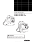
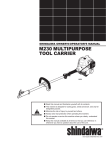
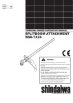
SHINDAIWA OWNER’S/0PERATOR'S MANUAL
EB501/EVC BLOWER
High Performance
WARNING!
Minimize the risk of injury to yourself and others!
Read this manual and familiarize yourself with the contents. Always wear eye and hearing protection when
operating this unit. Minimize the risk of injury: Read this
manual and familiarize yourself with its contents.
Part Number 68241-94310 Rev. 11/06
INTRODUCTION
IMPORTANT!
Before using this product, consult
local regulations concerning noise
restrictions and hours of operation!
The Shindaiwa EB501 has been
designed and built to deliver superior
performance and reliability without
compromise to quality, comfort, safety,
or durability.
Shindaiwa high performance
engines represent the leading edge of
2-cycle engine technology, and deliver
exceptionally high power at remarkably low displacement and weight. As
a professional owner/operator, you’ll
soon discover why Shindaiwa is simply
in a class by itself!
IMPORTANT!
The information contained in this
manual describes machines available
at the time of production. While every
attempt has been made to give you
the very latest information about your
Shindaiwa EB501 blower, there may
be some differences between your
machine and what is described here.
Shindaiwa Inc. reserves the right to
make changes in production without
prior notice, and without obligation to
make alterations to machines previously manufactured.
CAUTION!
The engine exhaust from this
product contains chemicals known
to the State of California to cause
cancer, birth defects or other reproductive harm.
1
CONTENTS
PAGE
Attention Statements............................ 2
Nomenclature........................................ 3
Specifications......................................... 4
Assembling the Blower........................ 4
Mixing Fuel........................................... 6
Filling the Fuel Tank............................ 7
Starting and Stopping the Blower....... 8
Adjusting Engine Idle Speed.............. 10
Adjusting the Harness........................ 11
Using the Blower................................ 12
Routine Maintenance.......................... 13
Spark Arrester Maintenance............. 15
Storage................................................. 16
Troubleshooting Guide...................... 17
Emission System Warranty................ 21
CAUTION!
This EB501 blower is equipped
with a spark-arresting muffler!
Never operate this machine
without both the muffler and spark
arrester installed and properly
functioning!
ATTENTION STATEMENTS
This manual contains special “attention
statements” surrounded by boxes and
preceded by the triangular Attention
Symbol.
WARNING!
A statement preceded by the word
“WARNING” contains information
that should be acted upon to prevent serious bodily injury.
CAUTION!
A statement preceded by the word
“CAUTION” contains information
that should be acted upon to prevent damaging your machine.
Additional attention statements that
are not preceded by the Attention
Symbol are:
IMPORTANT!
A statement preceded by the word
“IMPORTANT” is one that possesses
special significance.
NOTE:
A statement preceded by the word
“NOTE” contains information that is handy
to know and may make your job easier.
Read and follow this manual.
Failure to do so could result
in serious injury.
Wear eye and hearing
protection at all times during
the operation of this machine.
Do not operate this machine if
you are tired, ill or under the
influence of alcohol, drugs,
or medicine.
IMPORTANT!
The operational procedures described
in this manual are intended to help
you get the most from your machine
and also to protect you and others
from harm. These procedures are
general guidelines only, and are not
intended to replace any safety rules/
laws that may be in force in your area.
If you have any questions regarding
your EB501 blower, or if you do not
understand something in this manual,
your Shindaiwa dealer will be glad to
assist you.
For additional information, you may
also contact Shindaiwa Inc. at the
address printed on the back of this
manual.
WARNING!
Do not make unauthorized modifications to this machine!
2
NOMENCLATURE
Volute Case
Carburetor with Choke
and Primer
Spark Plug
Air Cleaner
Starter
Handle
Exhaust
Outlet
Throttle and
Stop Lever
Engine
Cover
Fuel Tank
Fuel Filler Cap
Handgrip
48002
90° Discharge
Tube
Figure 1
3
Flexible
Tube
Swivel
Tube
SPECIFICATIONS
Model................................................................................................................... EB501
Dimensions (L x W x H)...............................................................330 x 375x 475 mm
Engine Type.................... 2 cycle, catalyst, air cooled gas engine, vertical-cylinder
Bore & Stroke.............................................................. 41 x 33 mm (1.6 x 1.3 inches)
Displacement......................................................................... 43.6 cc (2.66 cu. inches)
Fuel/oil ratio.............. Gasoline/oil mixture (50:1 with ISO EGD or JASO FC class
2- cycle EngineOil)
Carburetor.............................................. Walbro diaphragm-type with primer pump
Ignition......................................................... All transistor electronic ignition system
Spark Plug...............................................................................................Champion CJ8
Starting..................................................................................................... Recoil starter
Stopping.......................................................................... Throttle lever (fuel shut-off)
Fuel Tank Capacity............................................................................2.1 liters (71 oz.)
Exhaust System........................................................................ Spark-arrester muffler
Air Filtration..............................................................................................Dry element
Weight (dry; without blower tubes), EB501...................................... 8.6 kg (19 lbs.)
Specifications are subject to change without notice.
Prior to Assembly
Before assembling, make sure you
have all the components required for a
complete unit:
n Handgrip (removable)
n 90° Discharge Tube
n Three Tube Clamps (115 mm,
100 mm, 85 mm) See figure 2.
n Flexible Tube
Standard Tools
n Swivel Tube
n Spark Plug Wrench
n Straight Tube
n Three Hex Wrenches
(3 mm, 4mm, 5mm)
n Nozzle Tube
ASSEMBLING THE BLOWER
1. Place the blower upright on the
ground or a sturdy work surface.
2. Fit the 90° discharge tube over the
blower outlet port, and secure with
the 115mm dia. clamp.
3. Slip the flexible tube over the opposite end of the 90° discharge tube,
and secure with the 100mm clamp.
4. Push the swivel tube into the
flexible tube, and then install and
tighten the 85mm clamp over the
rotating band on the swivel tube.
5. Slide the handgrip over the swivel
tube, and secure with the bolt,
washer, and nut.
4
ASSEMBLING THE BLOWER (continued)
115mm Clamp
Nut
Swivel
Tube
Handgrip
Bolt
Washer
85mm Clamp
48002A
90° Discharge Tube
90° Discharge Tube
Flexible Tube
100mm Clamp
Handgrip
Flexible Tube
Swivel Tube
Straight Tube
Nozzle Tube
48003
Figure 2
6. Grasp the straight tube as shown,
and push the tube over the
swivel tube locking pins (right).
See figure 3.
Tube Assembly
Align the lock pins with the
lock slots, and push the tubes
together.
7. Lock the straight tube to the swivel
tube by rotating the straight tube.
8. Grasp the nozzle tube and lock the
nozzle to the straight tube as in
Steps 6 and 7.
IMPORTANT!
Blower tube installation affects blower
balance and performance! Make sure
the tubes and nozzle are correctly
assembled per above, and that all
connections are tight.
48004D
Lock Pin
Lock Slot
Rotate clockwise to lock, making sure the 3 lines are aligned
on both tubes.
WARNING!
Danger from rotating impeller!
Stop the engine before installing or
removing the blower tubes! Never
perform any maintenance or assembly procedures on this machine while the engine is running!
5
48004C
Figure 3
MIXING FUEL
Fuel Requirements
n Use only fresh, clean fuel.
n Use only fuel with an octane rating
of 87 or above.
n Mix all fuel with ISO EGD or JASO
FC class 2-cycle Engine Oil at a
gasoline/oil ratio of 50:1 (1 gallon
gasoline to 2.6 oz. mixing oil).
CAUTION!
Use of mixing oil other than ISO
EGD or JASO FC rated oil can
lead to exessive carbon deposits.
WARNING!
Danger of fire!
Never transfer or store fuels in the
presence of combustible materials!
Before starting the engine, always
move the blower to a clear area
at least 10 feet (3 meters) away
from fuels and other combustible
materials!
IMPORTANT!
Mix only enough fuel for your immediate needs! If fuel must be stored
longer than 30-days, it should first
be treated with a stabilizer such as
StaBil™ or equivalent product!
CAUTION!
Never attempt to mix fuel in the
blower fuel tank! Always mix all fuels in a clean, approved container!
Some gasolines contain ethanol alcohol as an oxygenate!
Oxygenated fuels may cause
increased engine operating temperatures! Under certain conditions, alcohol-based fuels may also
reduce the lubricating qualities of
some mixing oils!
Never use any fuel containing
more than 10% ethanol alcohol by
volume!
Generic oils and some outboard
mixing oils are not intended for
use in high-performance air cooled
2-cycle engines, and should never
be used in your Shindaiwa blower!
6
FILLING THE FUEL TANK
Remove the
Fuel Filler
Cap
1. Place the blower upright on the
ground or on a sturdy work surface
and wipe any debris from around
the fuel cap.
2. Remove the fuel cap. See figure 4.
3. Fill the tank with clean, fresh fuel
(see page 6).
4. Replace the cap and wipe away
any spilled fuel before starting the
blower engine.
48005
Fuel
Tank
Figure 4
WARNING!
Danger of fire and burn
injury!
n Always use extreme care when
handling fuel! Fuel is highly flammable!
n Never operate this blower if fuel
system components are damaged
or are leaking!
n Never attempt to refuel the
engine while it is running!
n Never attempt to refuel a hot
engine! Always allow the blower
engine to cool before fueling!
7
n Never smoke or light any fires
near the blower or fuels!
n Always transport and store fuels
in an approved container!
n Never place flammable material
close to the engine muffler!
n Never operate the blower without a properly functioning muffler and spark arrester installed!
n Never operate this blower unless
it is properly assembled and in
good working condition!
STARTING AND STOPPING THE BLOWER
WARNING!
Danger from rotating impeller!
The impeller will rotate whenever
the blower is operating! Never
operate this blower unless the
intake cover and blower tubes
are properly installed and in good
working order!
Danger from thrown dust or debris! Always wear eye and respiratory protection when operating this
machine! Never direct the blower
stream toward people or animals!
Never operate this blower unless
all controls are properly installed
and in good working order.
CAUTION!
Avoid continuous running of the engine without the blower tubes installed,
or if the intake cover or blower tubes are blocked. Doing so can cause
engine overheating resulting in severe engine damage!
Starting Procedure
WARM OR COLD ENGINE
COLD ENGINE ONLY Choke the
1. While squeezing the throttle lock
lever, move the throttle lever to the
“engine idle” position. See figure 5.
Throttle Positions
Full
Throttle
2. Prime the
fuel system
by depressing the
fuel primer
bulb
repeatedly until
the bulb
fills with
fuel and
resistance
is felt. See
figure 6.
Lock Lever
3. Place the blower on the ground, and
hold the blower firmly with your left
hand on the volute case. See figure 7.
WARNING!
Engine
Idle
The engine cover will be hot after
blower operation!
Stop
4. Using your right hand, pull the
starter handle slowly until you feel
the starter engage.
48006
Figure 5
engine by moving the choke control
UP (choke is closed).
Choke Control (open
position shown)
Pull upward
rapidly
48007
48008
Fuel Primer Bulb
Figure 6
Figure 7
8
5. As the starter engages, pull the
starter handle upward rapidly.
6. If necessary, repeat Steps 4 and 5
2–3 times until the engine starts.
CAUTION!
The recoil starter can be damaged
by abuse!
n Never pull the starter cord to its
full length.
n Always engage the starter
before cranking the engine.
Always rewind the starter cord
slowly.
IMPORTANT!
If the engine continues to run with the
throttle lever in the “off” position, stop
the engine by moving the choke control
UP to the fully closed position. Adjust
idle setting as decribed on page 10.
IF THE ENGINE DOES NOT START
Repeat the appropriate starting procedures for “warm” or “cold” engine. If
the engine still will not start, follow the
“Starting a Flooded Engine” procedure
as below:
WARNING!
WHEN THE ENGINE STARTS
1. As the engine warms, open the
choke gradually by slowly moving
the choke control down to the fully
OPEN position.
2. Run the engine at idle speed until
operating temperature is reached
(2-3 minutes).
The blower should now be ready
for use.
STOPPING THE ENGINE
1. Cool the engine by allowing it to
run at idle for 2–3 minutes.
2. While squeezing the throttle lock
lever, push and hold the throttle
lever down until the engine stops.
See figure 8.
Throttle
Lever
Squeeze Lock
Lever
Push Down To Stop
9
STARTING A FLOODED ENGINE
1. Disconnect the spark plug lead,
and use the spark plug wrench to
remove the spark plug in a counter-clockwise direction (see the
diagram on page 14).
2. If the spark plug is fouled or is
soaked with fuel, clean or replace
the plug as required.
3. Clear excess fuel from the combustion chamber by cranking the engine several times while the spark
plug is removed.
4. Install and tighten the spark plug,
and reconnect the spark plug lead.
5. Repeat the starting procedures for
“warm engine.”
48009
Figure 8
Never operate the blower unless all
controls are properly installed and
in good working order. Never operate the blower if the intake cover or
blower tubes are missing or damaged!
6. If the engine still fails to start or
fire, refer to the troubleshooting
flow chart at the end of this manual.
ADJUSTING ENGINE IDLE SPEED
1. Start the engine by following the
procedures described on the preceding pages. Make sure the thottle
lever is in the "idle" position.
Idle Decrease
Idle
Increase
2. Run the engine at idle speed until
operating temperature is reached
(2-3 minutes).
3. Loosen the throttle cable locknut.
See figure 9.
4. Turn the cable adjuster in or out
until the engine idles smoothly at
approximately 2500-3000 rpm.
Cable
Adjuster
n Turn the throttle cable adjuster
clockwise to decrease engine idle
speed.
n Turn the throttle cable adjuster
counter-clockwise to increase engine idle speed.
5. Tighten the throttle cable locknut
securely.
IMPORTANT!
A clean and unrestricted airflow is
essential to your blower’s engine
performance and durability! Before
attempting any carburetor adjustments, inspect and clean the engine
air filter as described on page 13 of
this manual.
48010
Figure 9
Throttle Cable
Locknut
IMPORTANT!
Blower tubes and intake cover must
be in place while adjusting engine
idle! Engine idle speed will also be
affected if either the intake cover or
blower tubes are blocked or incorrectly installed!
10
ADJUSTING THE HARNESS
The Shindaiwa EB501 Blower features
an advanced harness system that helps
ensure maximum operator comfort
and ease of operation.
The adjusting strap lets the user
determine how far apart the
upper harness loops are
positioned. Easy to
customize for maximum
comfort.
n The shoulder harness is filled with
soft padding for reduced operator
fatigue.
n The simplified adjustment system
makes it easy to match the harness
to every body size and type. See
figure 10.
Adjustment Holes
Adjusting Strap
Comfortable
Back Pad
48019
Pull on the loops to
quickly tighten the harness straps
Quick-disconnect
Spring Hook
Quick-adjust
Buckle
To tighten straps…
To loosen straps…
Quick-adjust
Buckle
Pull strap
loops down
48019A
Figure 10
11
Pull the
quickadjust
buckles
up…
…and
pull the
straps
down.
48019B
USING THE BLOWER
THINK SAFETY!
OPERATING TIPS
In the hands of an experienced operator, the EB501 can efficiently move a
wide variety of debris ranging from
grass clippings to gravel. As a general
rule, operate your EB501 at the lowest
throttle setting required to get the job
done:
Wear close-fitting clothing to protect
your legs and arms, and Do not wear
clothing or jewelry that could get caught
in machinery! Secure hair so that it is
above shoulder length!
n Use low throttle settings when
clearing lightweight materials from
around lawns or shrubbery.
n Use medium to higher throttle settings to move grass or leaves from
parking lots or walkways.
n Use full throttle when moving heavy
loads such as dirt or snow.
IMPORTANT!
Blower noise increases at higher
throttle settings! Always use the lowest throttle setting required to get the
job done!
Wear eye protection that meets ANSI
Z87.1 such as a face shield or goggles while
operating this machine!
Wear hearing protection
when operating the blower.
Wear a dust mask to reduce the risk
of inhalation injuries.
48011B
Never operate
the blower if any
component parts are
damaged, loose, or
missing!
Always be aware of the strength
and direction of the blower
discharge stream! Never direct the
blower discharge stream toward
people or animals!
Never operate the blower when
visibility is poor.
Figure 11
12
ROUTINE MAINTENANCE EVERY 10 HOURS
IMPORTANT!
(more frequently in dusty conditions)
Remove the Element
Maintenance, replacement or repair of
emission control devices and sysCover Latch
tems may be performed by any repair
establishment or individual. However,
warranty repairs must be performed
by a dealer or service center authorized by Shindaiwa Corporation The
use of parts that are not equivalent in
performance and durability to authorized parts may impair the effectiveness of the emission control system
Cover
Element
and may have a bearing on the
outcome of a warranty claim.
48013
Snap the cover up from the
bottom to remove.
WARNING!
Before performing any maintenance on this blower, stop the
engine and disconnect the spark
plug wire!
Daily Maintenance
n Remove dirt and debris from the
blower exterior.
n Inspect the engine, tank, and hoses
for possible fuel leaks, and repair as
necessary.
n Inspect the entire blower for loose,
damaged, or missing components,
and repair as necessary.
n Inspect the engine cooling fins for
accumulations of dirt or debris, and
clean as necessary.
CAUTION!
Dirty or damaged cooling system
components may allow the engine
to overheat, possibly causing serious engine damage!
Operating the blower with loose,
missing, or damaged components
could allow the engine to overspeed, possibly causing serious
engine damage!
13
Figure 12
1. Remove the air cleaner cover by
gently lifting the cover latch. See
figure 12.
2. Inspect the filter. If the element is
damaged or distorted, replace it
with a new one.
IMPORTANT!
The EB501 uses a special high capacity dry-type air filter element. The filter
should not be cleaned with a liquid
cleaner and must NEVER be oiled!
3. Tap filter gently on a hard surface
to disloge debris from element or
use compressed air to blow debris
from the air filter element.
IMPORTANT!
Direct the air stream at the inside face
of the filter only!
4. Wash the filter cover with soap and
water and blow dry.
5. Install the filter element and cover
in the reverse order of removal.
CAUTION!
Never operate the blower if the air
cleaner assembly is damaged or
missing!
EVERY 10/15 HOURS
to remove
48017
0.024" (0.6mm) gap
EVERY 50 HOURS
(more frequently if reduced
performance is noted)
n INSPECTION Inspect the entire
blower and tubes for damage,
including loose or missing components, and repair as necessary.
n SPARK PLUG Replace the spark
plug with a Champion CJ8 or
equivalent, gapped to 0.024 inch
(0.6mm).
Champion CJ8
Spark Plug
Wire
Hook
48014
Figure 14
1. Use the spark plug wrench to remove the spark plug (turn counterclockwise to remove). See figure
13.
48015
Fuel Filter
Fuel Tank
2. Clean and adjust the spark plug
gap to 0.024” (0.6mm). Replace any
damaged or visibly worn plug with a
Champion CJ8 or equivalent. See
figure 13.
Figure 14
FUEL FILTER Use a bent piece of
wire to extract the fuel filter from inside the fuel tank, and then remove
and replace with a new element. See
figure 14.
3. Install the spark plug finger-tight
in the cylinder head, then tighten it
firmly with the spark plug wrench.
Avoid overtightening.
CAUTION!
Do not nick or perforate fuel tube
with wire hook!
CAUTION!
Never allow dirt or debris to enter
the cylinder bore! Before removing
the spark plug, thoroughly clean
the spark plug and cylinder head
area!
Allow the engine to cool before
servicing the spark plug! Cylinder
threads can be damaged by tightening or loosening the spark plug
while the engine is hot!
Before reinstalling the filter, inspect
the condition of the fuel line. If
damage or deterioration are noted,
the blower should be removed from
service until it can be inspected by a
Shindaiwa-trained service technician.
n COOLING SYSTEM Use a wood
or plastic scraper and a soft brush
to remove dirt and debris from the
cylinder fins and crankcase.
14
135-HOUR MAINTENANCE
Ever y 135 hours of operation,
remove and clean the muffler.
Remove the Engine Cover
Engine Cover
Muffler Body
First, remove the
spark plug
Muffler Screw
Retaining Tab
Engine
Cover
Arrester
Screen
Remove four Allenhead capscrews
48016D
5 mm
Lower
Screw
48018
6 mm
Muffler
Screws
Figure 15
Gasket
WARNING!
Never operate the machine with
a damaged or missing muffler
or spark arrester! Operating with
missing or damaged exhaust components is a fire hazard and could
also damage your hearing.
Remove the Muffler.
1. Remove the spark plug.
2 Use the 4mm Allen wrench to remove
the four engine cover screws , and
then slide the cover from the engine
taking care not to misplace the cylinder-to-cover insulating gasket. See
figure 15.
Exhaust
Tube
Tail Cap
Mounting
Screws
Figure 16
5. Use a plastic scraper or wire brush to
remove carbon deposits from the arrester
screen, exhaust tube and tail cap.
6. Inspect the screen carefully, and replace
any screen that has been perforated, distorted, or is otherwise unserviceable.
7. Gently tap the muffler on a wood surface
to dislodge any loose carbon.
8. Inspect the cylinder exhaust port for
3. Pry the muffler screw retaining
carbon buildup.
tabs away from the screw heads and
IMPORTANT!
remove the two 6 mm muffler screws.
Remove the 5 mm lower muffler
If you note excessive carbon buildup, conscrew, then remove the muffler assem- sult your servicing dealer.
bly from the engine. See figure 16.
9. Reassemble the muffler in the reverse
Remove the Spark Arrester.
order of disassembly.
4. Use the screwdriver to remove the
IMPORTANT!
three exhaust tube mounting screws,
and then remove the tail cap, exhaust
Reset the muffler screw retaining tabs to
tube, gasket, and arrester screen. See prevent the muffler screws from loosening.
figure 16.
15
STORAGE
(30 days or longer)
n CLEANING Thoroughly clean the
blower exterior.
n INSPECTION Inspect the entire
blower and tubes for damage,
including loose or missing components, and repair as necessary.
n LUBRICATION Remove the spark
plug, and then pour approximately
1/4-oz of 2-cycle oil into the cylinder
through the spark plug hole. Before
reinstalling the spark plug, pull the
recoil starter gently 2–3 times to
distribute the oil over the cylinder
walls.
n FUEL Drain the fuel tank, and then
clear any remaining fuel from the
n AIR CLEANER Remove, clean,
carburetor and lines by running the
and reinstall the filter element as
blower until it stops from lack of fuel.
described under “daily maintenance.”
CAUTION!
Never store this product with
any fuel remaining in the tank,
fuel lines, or carburetor! Your
Shindaiwa warranty does not include coverage for damage caused
by “stale” or contaminated fuels!
n STORAGE Store the blower in a
clean, dry, dust-free environment.
16
TROUBLESHOOTING GUIDE
ENGINE DOES NOT START
What To Check
Possible Cause
Remedy
Faulty recoil starter.
Fluid in the crankcase.
Internal damage.
Consult with an authorized
servicing dealer.
NO
Loose spark plug.
Excess wear on
cylinder, piston, rings.
Tighten and re-test.
Consult with an authorized
servicing dealer.
NO
Fuel/mixture incorrect,
stale, contaminated.
Refill with fresh fuel of the correct
mixture (gasoline and ISO EGD
or JASO FC class 2-cycle Engine Oil).
Check for clogged fuel
filter and/or vent.
Clean as required;
re-start.
Faulty ignition ground.
Consult with an authorized
servicing dealer.
If the plug is wet, excess
fuel may be in the
cylinder.
Crank the engine with the
plug removed, replace the
plug, and re-start.
The plug may be fouled
or improperly gapped.
Clean and re-gap the plug to
0.24 inch (0.6 mm); re-start.
The plug may be
damaged internally or
of the wrong size.
Replace the plug with a
Champion CJ8.
Does the engine NO
crank?
YES
Good
compression?
YES
Does the tank
contain fresh
fuel of the
proper grade?
YES
Is fuel filling the NO
fuel primer bulb
during priming
operations?
YES
Is there spark at NO
the spark plug
wire terminal?
YES
Check the
spark plug
17
TROUBLESHOOTING GUIDE (continued)
LOW POWER OUTPUT
What To Check
Is the engine overheating?
Possible Cause
Operator is overworking
the machine.
Remedy
Use lower throttle setting.
Improper fuel/oil ratio.
Refill with fresh fuel of the correct mixture (gasoline and ISO
EGD or JASO FC class 2-cycle
Engine Oil, 50:1 ratio.
Fallen leaves or dust on
the intake cover.
Clean the intake cover.
Fan, fan cover, or cylinder Clean, repair or replace as
fins are dirty or damaged. necessary.
Engine is rough
at all speeds. May
also have black
smoke and/or
unburned fuel at
the exhaust.
Carbon deposits in the
muffler.
Decarbonize muffler.(See 135
hr. maint. page 15).
Carbon deposits in the
combustion chamber
and/or exhaust port.
Consult with an authorized
servicing dealer.
Missing or damaged
blower tubes.
Replace missing or damaged
blower tubes.
Clogged air cleaner
element.
Clean or replace air cleaner
element.
Loose or damaged
spark plug.
Tighten or replace.
Air leakage or
clogged fuel line.
Repair or replace filter and/
or fuel line.
Water in the fuel.
Drain the fuel system, replace
the fuel.
Piston seizure.
Faulty carburetor
and/or diaphragm.
Consult with an authorized
servicing dealer.
18
TROUBLESHOOTING GUIDE (continued)
ADDITIONAL PROBLEMS
What To Check
Engine is
knocking.
Poor
acceleration.
Egine difficult
to shut off.
19
Possible Cause
Remedy
Overheating condition. Idle engine until cool; find
reason for overheat.
Improper fuel.
Check fuel octane rating.
Check for presence of
alcohol in fuel. Refuel as
necessary.
Carbon deposits in
combustion chamber
and/or exhaust port.
Consult with an authorized
servicing dealer.
Clogged air cleaner
element.
Clean the element.
Spark arrester is
clogged.
Clean the Spark arrester.
Clogged fuel filter.
Replace fuel filter.
Carburetor mixture
too lean.
Consult with an authorized
servicing dealer.
Idle speed set too low.
Set to 2500-3000 RPM.
Leaking or damaged
blower housing or tube
assembly.
Repair or replace components
as required.
Debris is tangled in
blower impeller blades.
Consult with an authorized
servicing dealer.
Overheated engine.
Idle engine to cool.
Throttle cable is
incorrectly adjusted.
Choke engine to stop.
Adjust thottle cable.
Overheating due to
incorrect spark plug.
Replace spark plug with
Champion CJ8.
(page 15).
TROUBLESHOOTING GUIDE (continued)
ADDITIONAL PROBLEMS
What To Check
Engine stops
abruptly.
Excessive
vibration.
Engine overspeeding.
Possible Cause
Remedy
Throttle lever is the
''OFF'' position.
Move throttle lever to the
run position and reststart.
Fuel tank empty.
Refuel.
Clogged fuel filter.
Replace fuel filter.
Water in the fuel.
Drain; replace with clean
fuel. Replace fuel filter.
Shorted spark plug or
loose terminal.
Clean or replace spark plug;
tighten the terminal.
Ignition failure.
Consult with an authorized
servicing dealer.
Piston seizure.
Consult with an authorized
servicing dealer.
Warped or damaged
blower fan.
Consult with an authorized
servicing dealer.
Loose bolt or fastener
Tighten as required.
Internal engine damage.
Consult with an authorized
servicing dealer.
Damaged A-V cushions.
Replace cushions.
Blower intake or
discharge ports or tubes
are clogged with debris.
Remove debris.
Impeller blades are
missing or damaged.
Consult with an authorized
servicing dealer.
20
Emission System Warranty Statement
Your Warranty Rights and Obligations
The California Air Resources Board, the U.S. Environmental Protection
Agency and Shindaiwa Corporation are pleased to explain the exhaust and
evaporative emission control system warranty on your new small off-road (nonroad) engine.
In California, new small off-road engines must be designed, built, and
equipped to meet the State’s stringent anti-smog standards. In other states, new
1997 and later non-road engines must meet the Federal EPA’s stringent antismog standards.
Shindaiwa Corporation must warrant the emission control system on your small
off-road engine for the periods of time listed below, provided there has been no
abuse, neglect, or improper maintenance of your small off-road engine.
Your engine exhaust and evaporative emission control system includes parts
such as the carburetor, fuel tank, the ignition system and, if equipped, the catalytic converter. These components are specifically listed below.
Where a warrantable condition exists, Shindaiwa Corporation will repair your
small off-road engine at no cost to you including diagnosis, parts, and labor.
Manufacturer’s Warranty Coverage
When sold within the U.S., this engine’s emission control system is warranted
for a period of two (2) years from the date this product is first delivered to the
original retail purchaser.
During the warranty period, Shindaiwa Corporation will, at their option, repair or replace any defective emission-related component on this engine. During
the original Warranty Period, these Warranty Rights are automatically transferable to subsequent owners of this product.
What is Covered by this Warranty
1. Carburetor Internal Components
n Throttle Valve, Needle, Jet, Metering Diaphragm
2. Fuel Tank
3. Ignition System Components
n Ignition Coil
n Flywheel Rotor
4. Catalytic Converter (if originally equipped)
The emission control system for your particular Shindaiwa engine may also
include certain related hoses and connectors.
21
Owners Warranty Responsibilities
As the small off-road engine owner, you are responsible for the performance of the required maintenance listed in this owners manual. Shindaiwa
Corporation recommends that you retain all receipts covering maintenance on
your small off-road engine, but Shindaiwa Corporation cannot deny warranty
solely for the lack of receipts or for your failure to ensure the performance of all
scheduled maintenance.
As the small off-road engine owner, you should be aware, however, that
Shindaiwa Corporation may deny you warranty coverage if your small off-road
engine or a part has failed due to abuse, neglect, improper maintenance, or
unapproved modifications.
You are responsible for presenting your small off-road engine to an authorized Shindaiwa Dealer as soon as a problem exists. The warranty repairs should
be completed in a reasonable amount of time, not to exceed 30 days.
If you have any questions regarding your warranty rights and responsibilities,
you should contact a Shindaiwa customer service representative at (503) 6923070 or your local Shindaiwa Dealer.
Consequential Damages
In the event that other component parts of this product are damaged by the
failure of a warranted part, Shindaiwa Corporation will repair or replace such
component parts at no charge to you.
What is Not Covered
n Failures caused by abuse, neglect, or improper
maintenance procedures.
n Failures caused by the use of modified or non-approved parts or attachments.
This Warranty is Administered by:
Shindaiwa Inc.
11975 S.W. Herman Rd.
Tualatin, OR 97062
(503) 692-3070
22
Shindaiwa Inc.
11975 S.W. Herman Rd.
Tualatin, Oregon 97062 USA
Telephone: 503 692-3070
Fax:
503 692-6696
www.shindaiwa.com
Shindaiwa Corporation
Head Office:
6-2-11, Ozuka-Nishi
Asaminami-Ku, Hiroshima
731-3167, Japan
Telephone: 81-82-849-2220
Fax:
81-82-849-2481
© 2006 Shindaiwa, Inc.
Part Number 68241-94310
Printed in Japan
Shindaiwa is a registered trademark
of Shindaiwa, Inc.
Specifications subject to change without
notice.