1
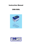
Operating instructions Status: 2012-09 Operating instructions TSM-11 hopper call-up control Art. no.: 90.0010.50 fimotec-fischer GmbH & Co. KG Friedhofstraße 13 D -78588 Denkingen Tel: Fax: +49 (0)74 24 - 88 4-0 +49 (0)74 24 - 88 4-50 E-mail: Internet: [email protected] www.fimotec.de Operating instructions TSM-11 The duplication, sharing or use of this documentation or its contents is only allowed with written permission. Violations result in liability for damages. All rights reserved, including such which arise from granted patents or registration of a utility patent or design. Copyright © fimotec-fischer GmbH & Co. KG 2012 Page 2 Status as of 09 / 2012 Operating instructions TSM-11 Information and explanations Target group These operating instructions will help you to use the described product safely and as intended. They are directed toward qualified skilled personnel*. Qualified personnel are people who have been authorized by persons responsible for the safety of the system to execute the required activities and are able to recognize potential dangers and avoid them based on their training, experience and instruction, as well as their knowledge of standards, regulations, accident prevention regulations and operating conditions (definition of skilled personnel according to IEC 364). Read these operating instructions before you install the device, use it or carry out work on it. Also pass on these operating instructions to other users. Definition of the warnings and symbols Warnings are indicated by danger symbols and signal words. The table shows what hazards and possible consequences the symbols, signal words and colours indicate. Signal word ACHTUNG Definition Consequences Directly threatening danger Death or extremely serious injuries Dangerous situation Potential death or extremely serious injuries Dangerous situation Minor to moderately serious injuries Risk of property damage Damage to the machine, its environment and the product Warnings can also have other warning signs: Example: Warning of electrical current! These symbols indicate the type of hazard. Term definitions Term Definition User Persons who use the device installed by the manufacturer in its ready-touse version. EMC Electromagnetic compatibility with electrical and electromagnetic influences. Skilled personnel Qualified personnel with the appropriate education, training and experience. Device Designation for the hopper control TSM-11 in these operating instructions. Machine manufacturer Persons who install the device in the intended construction (machine) and who manufacture the ready-to-use version. Status as of 09 / 2012 Page 3 Operating instructions TSM-11 Table of contents 1 PRODUCT OVERVIEW ......................................................................................................................... 5 1.1 Scope of delivery .................................................................................................................................... 5 1.2 Properties ............................................................................................................................................... 5 1.2.1 1.2.2 1.2.3 General ........................................................................................................................................................................................... 5 Output data ..................................................................................................................................................................................... 5 Inputs .............................................................................................................................................................................................. 5 SAFETY INFORMATION .................................................................................................................................. 6 1.3 Intended use ........................................................................................................................................... 6 1.4 Basic safety information ......................................................................................................................... 6 1.4.1 Transport and storage .................................................................................................................................................................... 6 2 INSTALLATION ..................................................................................................................................... 7 2.1 Hardware installation .............................................................................................................................. 7 2.2 Motor connection .................................................................................................................................... 7 2.3 Fuse protection ....................................................................................................................................... 7 3 OPERATION .......................................................................................................................................... 8 3.1 Hopper belt ............................................................................................................................................. 8 3.2 Hopper filling level check........................................................................................................................ 9 4 TECHNICAL DATA .............................................................................................................................. 10 5 TERMINAL ASSIGNMENTS ............................................................................................................... 11 6 DIMENSIONS ....................................................................................................................................... 11 7 MAINTENANCE AND CARE ............................................................................................................... 12 7.1 Regular tests ........................................................................................................................................ 12 7.2 Decommissioning and disposal ............................................................................................................ 12 8 ACCESSORIES AND OPTIONS ......................................................................................................... 13 8.1 The plug connectors listed below are available as accessories: ......................................................... 13 8.2 The connection lines listed below are available as accessories: ......................................................... 13 8 ACCESSORIES AND OPTIONS ......................................................................................................... 13 Page 4 Status as of 09 / 2012 Operating instructions TSM-11 1 Product overview 1.1 Scope of delivery TSM-11 hopper control Operating instructions 1.2 Properties 1.2.1 General Mains switch Consumer output for 230 V AC condenser motor Setting the parameters via DIP switches and trimmers All connections have a pluggable design. Type of protection IP54 1.2.2 Consumer output 230 V AC, max. 3 A PNP output (hopper filling level check) 24 V DC Potential-free output (malfunction) 230 V AC / 6 A 1.2.3 Output data Inputs Sensor input, level sensor Sensor input, filling level check, hopper Potential-free input, control disable Status as of 09 / 2012 Page 5 Operating instructions TSM-11 Safety information 1.3 Intended use The TSM-11 device is a piece of electrical equipment intended for use in supply mechanisms or automation systems. The device is designed for regulating and controlling hopper systems. The electrical components listed here are called "devices" in the industrial parlance, but are not devices which can be used or connected or machines in the sense of the "Device safety law", the "EMC law" or the "EC Machinery Directive", but components. Only when these components are integrated in the construction of the machine manufacturer is the ultimate mode of operation defined. The machine manufacturer is responsible for making sure that the construction meets the existing legal regulations. 1.4 Basic safety information The following warnings both serve for the personal safety of the user as well as the safety of the described products and the devices connected to them. Non-observance can lead to death, serious bodily injury or property damage. DANGER Life-threatening danger due to electric shock! Disconnect the device from the supply voltage before any intervention. Before opening the device, wait for at least 30 seconds until the residual voltage has dissipated. Check to make sure there is no voltage before any intervention. Only skilled electricians may work on electrical equipment. Before commissioning, make sure that the voltage supply agrees with the nominal values of the device. Check the electrical equipment of the machine regularly. Deficiencies, such as loose connections, damaged or scorched lines, must be fixed immediately. Observe the valid accident prevention and safety regulations for your application. In particular, observe both the general and the regional installation and safety regulations for working with dangerous voltages (e.g. EN 50178) as well as the regulations having to do with the proper use of tools and the use of personal safety equipment. The Emergency Stop mechanisms must remain in effect in all operating modes. Unlocking the Emergency Stop mechanisms must not result in uncontrolled reactivation. 1.4.1 Transport and storage Problem-free and safe operation of this device require proper transport, storage, setup and installation, as well as careful operation and maintenance. The device must be protected against mechanical impacts and vibrations during transport and storage. Protection against moisture, water and impermissible temperatures (see chapter 4Technical data) must also be guaranteed. Page 6 Status as of 09 / 2012 Operating instructions TSM-11 2 Installation ATTENTION 2.1 If the device is not correctly connected, this can lead to the failure or complete destruction of the device (and the connected load). Hardware installation The TSM-11 is a device for installation outside of a control cabinet and has IP54 protection. The device can be installed in any position. Mains connection The mains must be connected according to the valid regulations. The connection is made via terminal "X10". The pin assignments are as follows: Pin 1 230 V AC Pin 2 N Neutral conductor PE Connection for the ground protection conductor Here, make sure that L, N and PE are correctly allocated, since otherwise, the main voltage could be connected to touchable parts of the circuit (for a connection diagram, see chapter 6 "Pin assignments") or the device could be destroyed. All touchable, electrically conductive housing parts must be grounded according to the valid regulations. The connection must be made with at least a 0.75 mm² line cross-section. 2.2 Motor connection The connection is made via the Hirschmann GDM3011 plug, which projects out of the X11 screw connection. The pin assignments are as follows: 1 2 3 PE N L N via condenser Connection for the ground protection conductor The 230 V AC motor is connected to this connection. 2.3 Fuse protection The fuse protection on the primary side depends on the line cross-section. However, it must be designed to have a B6 line protection switch at minimum. The devices are also protected with internal fuses. Consumer output 3.15 A, slow-blow Control electronics 200 mA, slow-blow Caution!: Leakage currents against PE might occur due to EMC-related suppressor components. These are harmless, however, when an industry-standard RCD switch is used with a tripping current of 0.3 A. Status as of 09 / 2012 Page 7 Operating instructions TSM-11 3 Operation The device is set via DIP switches and trimmers. These are located directly under the front cover. 3.1 Hopper belt General The workpiece in the area around the oscillating shell is detected via a sensor. If no workpiece is detected by the sensor, the hopper control switches the drive on for the hopper belt. Various functions are available for the drive: Symbol Function Drive mode Drive switch-on time Sensor input Malfunction tmalfunction Switch-on delay tbelt Drive pause Designation DIP switch, left: DIP switch, right: DIP switch, left: DIP switch, right: DIP switch, left: DIP switch, right: Trimmer: Trimmer: Drive runs continuously. Drive runs on and off in a cycle. Drive (clock mode) switch-on time 1 s. Drive (clock mode) switch-on time 2.5 s. Sensor input signal (level sensor) N.O. not inverted Sensor input signal (level sensor) N.C. inverted Switch-on delay malfunction 35…180 s. Switch-on delay sensor signal (level sensor) 0…45 s. Pause drive (clock mode) 0.5…15 s. Trimmer: tpause Drive runs continuously: The level sensor does not detect a workpiece in the subsequent machine and switches the drive on after the time tbelt has elapsed. The drive runs until the level sensor detects a workpiece and switches off the drive. Drive runs cyclically: The level sensor does not detect a workpiece in the subsequent machine and switches the drive on after the time tbelt has elapsed. Drive switch-on time 1 s or 2.5 s, pause time tpause 0.5…15 s. Malfunction: After the switch-on delay tbelt has elapsed, the switch-on delay of the malfunction tmalfunction starts. If the level sensor is not actuated by a workpiece, tmalfunction runs off and the drive is switched off. The potential-free contact for the malfunction is actuated. The malfunction is acknowledged with the reset button on the front panel. Page 8 Plug connection X22 Designation Level sensor X21 Control disable X23 Malfunction 1: +24 V DC 2: 0 V 3: Signal 1:+24 V DC 2:Signal 1: Changer 2: N.C. 7: N.O. Status as of 09 / 2012 Operating instructions TSM-11 3.2 Hopper filling level check General: The filling level in the hopper can be monitored with the filling level check. Symbol Function Direction of rotation Sensor input Switch-on delay Ton Switch-off delay toff Designation DIP switch, left: DIP switch, right: DIP switch, left: DIP switch, right: Trimmer: Drive direction of rotation clockwise. Drive direction of rotation counterclockwise Sensor input signal (filling level sensor) N.O. not inverted Sensor input signal (filling level sensor) N.C. inverted Switch-on delay, filling level 0…20 s. Trimmer: Switch-off delay, filling level 0…20 s. Switch-on delay The filling level in the hopper is monitored with a light barrier. If a lack of workpieces is detected by the sensor, the switch-on delay ton starts. After this time elapses, the lack of workpieces output is actuated. Switch-off delay Once the lack of workpieces in the hopper has been rectified, the output is reset via the adjustable switch-off delay toff. The lack of workpieces output drops out. Plug connection X24 X25 X26 Status as of 09 / 2012 Designation Filling level sensor Receiver Filling level sensor Transmitter Lack workpieces 1: +24 V DC 2: 0 V 4: Signal 1: +24 V DC 8: 0 V of 1: Signal 5: 0 V Page 9 Operating instructions TSM-11 4 Technical data Supply voltage: 230 V AC (other voltages possible after consultation) Supply voltage tolerance: ± 10 % Mains frequency: 50 Hz (other frequencies possible after consultation) Consumer output current max 3 A Consumer output voltage: 230 V AC Level sensor [E] 24 V DC / 50 mA Disable [I] N.O. contact, potential-free contact load 24 V DC Malfunction [O] Changer, potential-free contact load 230 V AC / 6 A Filling level check, light barrier [I] 24 V DC / 50 mA Filling level check, signal lamp [O] 24 V DC / 80 mA Lack of workpieces [A] 24 V DC / 50 mA Type of protection: IP54 Permissible ambient temperature 5°C to 45°C Permissible relative humidity max.95 %, non-condensing. Dimensions: (h)115,25 mm x (w)125 mm x (d)58 mm EMC Interference emissions and noise immunity in acc. with EN 61000-6-x Noise immunity in acc. with EN 61000-4-x Electrostatic discharge strength (ESD) IEC / EN 61000-4-2 HF irradiation IEC / EN 61000-4-3 ("Burst") IEC / EN 61000-4-4 ("Surge") IEC / EN 61000-4-5 HF current infeed IEC / EN 61000-4-6 Voltage drop, voltage interruption IEC / EN 61000-4-11 Page 10 Status as of 09 / 2012 Operating instructions TSM-11 5 Terminal assignments ATTENTION If the device is not correctly connected, this can lead to the failure or complete destruction of the device (and the connected load). Plug connection X10 X11 Designation Mains feed Load output 1: 230 V AC 2: N PE: Protective conductor 1: N 2: L 3: N condenser PE: PE ground Mains switch illuminated Acknowledge malfunction reset 6 Dimensions Status as of 09 / 2012 Page 11 Operating instructions TSM-11 7 Maintenance and care 7.1 Regular tests The devices are usually maintenance-free. The electrical equipment of the machines are still to be checked regularly by skilled electricians. If it's dirty, clean the touchscreen with a conventional window cleaner and a soft, lint-free cloth. 7.2 Decommissioning and disposal The device is to be decommissioned by skilled electrical personnel while complying with the valid safety regulations. The packaging of the converter can be recycled. Please keep the packaging for later use. Easily removable screw connections allow the device to be disassembled into its components. These individual components can be recycled. Please carry out disposal in agreement with the local regulations. Problematic materials must not be thrown away in the normal waste! Dispose of problematic materials properly, safely and in an environmentally-friendly manner. Page 12 Status as of 09 / 2012 Operating instructions TSM-11 8 Accessories and options 8.1 The plug connectors listed below are available as accessories: Function Level sensor connection Disable connection Malfunction connection Filling level sensor, receiver connection Filling level sensor, transmitter connection Lack of workpieces connection Mains supply line connection 8.2 Slot X22 X21 X23 X24 X25 X26 X10 Article number 91.3300.80 91.3300.70 91.3301.10 91.3300.90 91.3301.20 91.3300.10 91.3301.30 The connection lines listed below are available as accessories: Function Level sensor connection Level sensor connection Level sensor connection Level sensor connection Level sensor connection Level sensor connection Level sensor connection Level sensor connection Filling level sensor, rec. connection Filling level sensor, transm. connection Disable connection to FSM-137 / FS-16/18 / TD-16 Mains supply line Mains supply line Status as of 09 / 2012 Length, line 0.6 m, straight socket 0.3 m, angled socket 0.6 m, angled socket 0.4 m, angled socket 0.8 m, angled socket 1.0 m, angled socket 2.0 m, angled socket 5.0 m, angled socket 0.7 m, angled socket 0.7 m, angled socket Slot X22 X22 X22 X22 X22 X22 X22 X22 X24 X25 Article number 91.4200.01 91.4200.02 91.4200.03 91.4200.04 91.4200.05 91.4200.06 91.4200.07 91.4200.08 91.4200.43 91.4200.44 3.0 m X21 91.4280.01 3.0 m, with Schuko plug X10 3.0 m, open end of line X10 91.4290.01 91.4290.02 Page 13