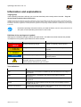
1
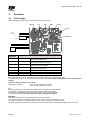
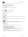
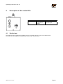
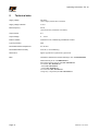
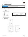
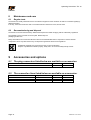
Operating instructions Status: 2014-10 Operating instructions Phase-angle controller TSL-16 for oscillating conveyor Art. no.: 90.0110.52 fimotec-fischer GmbH & Co. KG Friedhofstraße 13 D -78588 Denkingen Tel: Fax: +49 (0)74 24 - 88 4-0 +49 (0)74 24 - 88 4-50 E-mail: Internet: [email protected] www.fimotec.de Operating instructions TSL-16 The duplication, sharing or use of this documentation or its contents is only allowed with written permission. Violations result in liability for damages. All rights reserved, including such which arise from granted patents or registration of a utility patent or design. Copyright © fimotec-fischer GmbH & Co. KG2012 Page 2 Status as of 10 / 2014 Operating instructions TSL-16 Information and explanations Target group These operating instructions will help you to use the described product safely and as intended. They are directed toward qualified skilled personnel*. Qualified personnel are people who have been authorized by persons responsible for the safety of the system to execute the required activities and are able to recognize potential dangers and avoid them based on their training, experience and instruction, as well as their knowledge of standards, regulations, accident prevention regulations and operating conditions (definition of skilled personnel according to IEC 364). Read these operating instructions before you install the device, use it or carry out work on it. Also pass on these operating instructions to other users. Definition of the warnings and symbols Warnings are indicated by danger symbols and signal words. The table shows what hazards and possible consequences the symbols, signal words and colours indicate. Signal word ACHTUNG Definition Consequences Directly threatening danger Death or extremely serious injuries Dangerous situation Potential death or extremely serious injuries Dangerous situation Minor to moderately serious injuries Risk of property damage Damage to the machine, its environment and the product Warnings can also have other warning signs: Example: Warning of electrical current! These symbols indicate the type of hazard. Term definitions Term Definition User Persons who use the device installed by the manufacturer in its ready-touse version. EMC Electromagnetic compatibility with electrical and electromagnetic influences. Skilled personnel Qualified personnel with the appropriate education, training and experience. Device Designation (in these operating instructions) for the oscillating conveyor control unit TSL-16. Machine manufacturer Persons who install the device in the intended construction (machine) and who manufacture the ready-to-use version. Status as of 10 / 2014 Page 3 Operating instructions TSL-16 Table of contents 1 PRODUCT OVERVIEW ......................................................................................................................... 5 1.1 Scope of delivery .................................................................................................................................... 5 1.2 Device versions ...................................................................................................................................... 5 1.3 Properties ............................................................................................................................................... 5 1.3.1 1.3.2 1.3.3 General ........................................................................................................................................................................................... 5 Output data ..................................................................................................................................................................................... 5 Inputs .............................................................................................................................................................................................. 5 1.4 Intended use ........................................................................................................................................... 6 1.5 Basic safety information ......................................................................................................................... 6 1.5.1 Transport and storage .................................................................................................................................................................... 6 2 INSTALLATION ..................................................................................................................................... 7 2.1 Hardware installation .............................................................................................................................. 7 2.2 Mains connection ................................................................................................................................... 7 2.3 Oscillating conveyor connection ............................................................................................................. 7 2.4 Fuse protection ....................................................................................................................................... 7 3 OPERATION .......................................................................................................................................... 8 3.1 PCB settings ........................................................................................................................................ 8/9 3.2 Front panel ........................................................................................................................................... 10 3.3 Equalization .......................................................................................................................................... 10 4 DESCRIPTION OF THE CONTROL I/OS ........................................................................................... 11 4.1 Enable input.......................................................................................................................................... 11 5 TECHNICAL DATA .............................................................................................................................. 12 6 TERMINAL ASSIGNMENTS ............................................................................................................... 13 6.1 Power connection assignments............................................................................................................ 13 7 DIMENSIONS ..................................................................................................................................... 133 8 MAINTENANCE AND CARE ............................................................................................................... 14 8.1 Regular tests ........................................................................................................................................ 14 8.2 Decommissioning and disposal ............................................................................................................ 14 9 ACCESSORIES AND OPTIONS ......................................................................................................... 14 9.1 The plug connectors listed below are available as accessories:.................................................. 14 9.2 The connection lines listed below are available as accessories: ................................................. 14 Page 4 Status as of 10 / 2014 Operating instructions TSL-16 1 Product overview 1.1 Scope of delivery TSL-16 Operating instructions 1.2 Device versions The TSL-16 device is a phase-angle controller for actuating oscillating conveyor machines at a frequency of 50/100 Hz, 3000~ / 6000~ vibrations per minute and variable amplitude. 1.3 Properties 1.3.1 General Consumer outputs Mains input voltage compensation Type of protection IP54 1.3.2 Consumer output 50 Hz/100 Hz for 3000~ / 6000~ vibrations per minute Power adjustable from 0% to 100%. Min. / max. power limits. Adjustable soft start / soft stop 1.3.3 Output data Inputs Enable input for switching on/off without power Status as of 10 / 2014 Page 5 Operating instructions TSL-16 Safety information 1.4 Intended use The TSL-16 device is a piece of electrical equipment intended for use in supply mechanisms or automation systems. The device is designed for regulating and controlling oscillating conveyor systems. The electrical components listed here are called "devices" in the industrial parlance, but are not devices which can be used or connected or machines in the sense of the "Device safety law", the "EMC law" or the "EC Machinery Directive", but components. Only when these components are integrated in the construction of the machine manufacturer is the ultimate mode of operation defined. The machine manufacturer is responsible for making sure that the construction meets the existing legal regulations. 1.5 Basic safety information The following warnings both serve for the personal safety of the user as well as the safety of the described products and the devices connected to them. Non-observance can lead to death, serious bodily injury or property damage. DANGER Life-threatening danger due to electric shock! Even after the device is put out of operation by disconnecting the voltage, there is still dangerous electrical voltage on the internal circuit parts. Disconnect the device from the supply voltage before any intervention. Before opening the device, wait for at least 30 seconds until the residual voltage has dissipated. Check to make sure there is no voltage before any intervention. Only skilled electricians may work on electrical equipment. Before commissioning, make sure that the voltage supply agrees with the nominal values of the device. Check the electrical equipment of the machine regularly. Deficiencies, such as loose connections, damaged or scorched lines, must be fixed immediately. Observe the valid accident prevention and safety regulations for your application. In particular, observe both the general and the regional installation and safety regulations for working with dangerous voltages (e.g. EN 50178) as well as the regulations having to do with the proper use of tools and the use of personal safety equipment. The Emergency Stop mechanisms must remain in effect in all operating modes. Unlocking the Emergency Stop mechanisms must not result in uncontrolled reactivation. 1.5.1 Transport and storage Problem-free and safe operation of this device require proper transport, storage, setup and installation, as well as careful operation and maintenance. The device must be protected against mechanical impacts and vibrations during transport and storage. Protection against moisture, water and impermissible temperatures (see chapter 5Technical data) must also be guaranteed. Page 6 Status as of 10 / 2014 Operating instructions TSL-16 2 Installation ATTENTION 2.1 If the device is not correctly connected, this can lead to the failure or complete destruction of the device (and the connected load). Hardware installation The TSL-16 is designed for installation outside of a control cabinet (IP54 protection). If the device is mounted on a mounting plate made of metal, it can be installed with its entire area in contact with the plate or with spacers. If the device is mounted to a thermally non-conductive surface, it is to be mounted at a distance of at least 10 mm from its surface. 2.2 Mains connection The mains must be connected according to the valid regulations. It is connected via the attached Schuko "power" plug. All touchable, electrically conductive housing parts must be grounded according to the valid regulations. The connection must be made with at least a 1.0 mm² line cross-section. 2.3 Oscillating conveyor connection This is connected via the "X11" socket. The pin assignments are as follows: Pin 1 Connection for load Pin 2 Connection for load PE Connection for the ground protection conductor The oscillating conveyors are connected to these connections. 2.4 Fuse protection The fuse protection on the primary side depends on the line cross-section. However, it must be designed to have a B10 line protection switch at minimum. The devices are also protected with an internal fuse (F1 6.3 A, slow-blow). Caution!: Leakage currents against PE might occur due to EMC-related suppressor components. These are harmless, however, when an industry-standard RCD switch is used with a tripping current of 0.3 A. Status as of 10 / 2014 Page 7 Operating instructions TSL-16 3 Operation 3.1 PCB settings Device settings are made using the trimmer, slide switch and jumper. ON/ext Inv Min Max Ta/Te Te Off Control di Enable bl 0V 25/50 Hz +12 V DC N L PCB designation ON / ext Designation 25 / 50 Hz Slide switch Inv Jumper Te Off Jumper Min Max Ta/Te Trimmer Trimmer Trimmer Slide switch ON: Load output, active ext: external enable active 25 Hz: 3000 vibrations per minute 50 Hz: 6000 vibrations per minute Open: Input enable Closed: Input control disable Open: Soft start active Closed: Soft stop inactive Setting the minimum power Setting the maximum power Setting the soft start/stop time. ON/ ext If the slide switch is set to ON, the load output is activated independent of the external enable. If the slide switch is set to ext, the external enable is active. See section Fehler! Verweisquelle konnte nicht gefunden werden.. Half-wave / full-wave operation, 25 / 50 Hz Adjusting the vibrations, 25 Hz 3000 vibrations per minute 50 Hz 6000 vibrations per minute Inv With the inverter jumper, the external signal can be set as an enable or control disable. If the jumper is not plugged in (open), the external signal is used as an enable. If the jumper is plugged in (closed), the external signal is used as a control disable. For wiring, see section Fehler! Verweisquelle konnte nicht gefunden werden. MIN / MAX With the Min/Max trimmer, the oscillating conveyor can be equalized. The minimum capacity can be defined with the "Min" trimmer, when the load output is active. The maximum capacity can be defined with the "Max" trimmer, when the load output is active. Adjustment between the minimum and maximum conveyor values is done with the power potentiometer in the cover. Page 8 Status as of 10 / 2014 Operating instructions TSL-16 Ta/Te With the Ta/Te trimmer, the soft start and soft stop can be defined for the conveyor. Status as of 10 / 2014 Page 9 Operating instructions TSL-16 The startup time can be set between 0 and 2 s. The soft start and soft stop have the same time. Te Off The jumper Te Off is for deactivating the soft stop. If the jumper is not plugged in (open), the soft stop is active. If the jumper is plugged in (closed), the soft stop is inactive. 3.2 Front panel The device is switched on and the capacity is adjusted via the front panel. Power potentiometer Mains switch Mains switch Via the mains switch, the supply voltage is switched on/off. Once the device is switched on, the mains switch is illuminated in green. Power potentiometer The capacity is adjusted between P-min and P-max via the power potentiometer. The potentiometer is equipped with an interlock. 3.3 Equalization Attention !!! Since the equalization work on the device is only possible with mains voltage connected, this may only be carried out by a skilled electrician or an instructed person while observing the valid safety regulations. Working without mains voltage: Set jumper "Te Off" Set jumper "Inv" Set slide switch "25/50 Hz" The following described equalization work is done with the mains voltage on and load connected: Set Ta/Te potentiometer. Turn the "Min" potentiometer counterclockwise as far as it can go. Turn the "Max" potentiometer clockwise as far as it can go. Turn the power potentiometer in the housing cover to 0%. Turn the "Min" potentiometer clockwise until the desired minimum output power (P-min) is reached. Turn the power potentiometer in the housing cover to 100%. Turn the "Max" potentiometer counterclockwise until the desired maximum output power (P-max) is reached. Make sure that P-min < P-max. The two potentiometers do not influence each other during the equalization operation. The power can be set in the range between P-min and P-max with the power potentiometer in the housing cover. Page 10 Status as of 10 / 2014 Operating instructions TSL-16 4 Description of the control I/Os Plug connection X21 4.1 Designation External enable/control disable 1: +24 V DC 2: Enable signal Enable input The enable input is for switching the oscillating conveyor connected to the TSL-16 on and off without power. The enable must be designed via a potential-free contact. (e.g.: external switch) Status as of 10 / 2014 Page 11 Operating instructions TSL-16 5 Technical data Supply voltage: 230 V/AC (other voltages possible after consultation) Supply voltage tolerance: ± 10 % Mains frequency: 50 Hz (other frequencies possible after consultation) Output current 6A Output voltage: 0 … 210 V Enable / disable Contact 24 V DC, switched by potential free contact Type of protection: IP54 Permissible ambient temperature 5°C to 45°C Permissible relative humidity max.95 %, non-condensing. Dimensions: approx. (h)185 mm x (w)109 mm x (d)115 mm EMC Interference emissions and noise immunity in acc. with EN 61000-6-x Noise immunity in acc. with EN 61000-4-x Electrostatic discharge strength (ESD) IEC / EN 61000-4-2 HF irradiation IEC / EN 61000-4-3 ("Burst") IEC / EN 61000-4-4 ("Surge") IEC / EN 61000-4-5 HF current infeed IEC / EN 61000-4-6 Voltage drop, voltage interruption IEC / EN 61000-4-11 Page 12 Status as of 10 / 2014 Operating instructions TSL-16 6 Terminal assignments ATTENTION 6.1 7 If the device is not correctly connected, this can lead to the failure or complete destruction of the device (and the connected load). Power connection assignments Plug connection Power Designation Supply voltage X11 Load output Channel 1 F1 Fuse Schuko plug 230 V AC 50 Hz 1: Load 2: Load PE: PE 6.3 A, slow-blow Dimensions Status as of 10 / 2014 Page 13 Operating instructions TSL-16 8 Maintenance and care 8.1 Regular tests The devices are usually maintenance-free. The electrical equipment of the machines are still to be checked regularly by skilled electricians. If it's dirty, clean the touchscreen with a conventional window cleaner and a soft, lint-free cloth. 8.2 Decommissioning and disposal The device is to be decommissioned by skilled electrical personnel while complying with the valid safety regulations. The packaging of the converter can be recycled. Please keep the packaging for later use. Easily removable screw connections allow the device to be disassembled into its components. These individual components can be recycled. Please carry out disposal in agreement with the local regulations. Problematic materials must not be thrown away in the normal waste! Dispose of problematic materials properly, safely and in an environmentally-friendly manner. 9 Accessories and options 9.1 The plug connectors listed below are available as accessories: Function Enable/disable connection 9.2 Slot X21 Article number 91.3300.50 The connection lines listed below are available as accessories: Function Connection cable VK-40-1.5M Connection cable VK-40-3.0M Connection cable VK-40-5.0M Page 14 Length, line 1.5 m 3.0 m 5.0 m Slot X11 X11 X11 Article number 91.4304.20 91.4304.10 91.4304.00 Status as of 10 / 2014