1
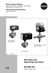
Electric Control Valves Types 3260/5857, 3260/5824, 3260/5825, 3260/3374, 3260/3274, 3260/3375 and 3260/5757-7, 3260/5725-7 Pneumatic Control Valves Types 3260/2780, 3260/3372, 3260-1, 3260-7 Type 3260/5857 Type 3260/5757 Type 3260-1 Type 3260/5824 Type 3260/5724 Type 3260/3374 Type 3260/2780-2 Type 3260/3274 Type 3260/3372 Mounting and Operating Instructions EB 5861 EN Edition April 2014 Definition of signal words DANGER! Hazardous situations which, if not avoided, will result in death or serious injury WARNING! Hazardous situations which, if not avoided, could result in death or serious injury 2 NOTICE Property damage message or malfunction Note: Additional information Tip: Recommended action EB 5861 EN Contents 1 General safety instructions..............................................................................5 2 Design and principle of operation...................................................................6 2.1 Technical data of Type 3260 Three-way Valve...................................................8 2.2 Possible combinations (valve/actuator).............................................................9 2.3 Permissible differential pressures....................................................................10 2.4Nameplate...................................................................................................11 2.5 Customer inquiries........................................................................................11 3 Installation...................................................................................................12 3.1 Mounting position.........................................................................................12 3.2Strainers......................................................................................................13 3.3 Additional mounting instructions....................................................................13 4 Mounting, connecting and configuring the actuator........................................13 5 Attachment..................................................................................................14 5.1Connection...................................................................................................15 5.2 Configuration...............................................................................................15 6 Dimensions and weights...............................................................................16 EB 5861 EN 3 General safety instructions 1 General safety instructions For your own safety, follow these instructions concerning the mounting, start up and operation of the control valve: −− The control valves must be mounted, started up or serviced by fully trained and qualified personnel only; the accepted industry codes and practices are to be observed. Make sure employees or third persons are not exposed to any danger. All safety instructions and warnings given in these mounting and operating instructions, particularly those concerning installation, start-up and maintenance, must be strictly observed. −− To ensure appropriate use, only use the control valve in applications where the operating pressure and temperatures do not exceed the specifications used for sizing the valve at the ordering stage. The manufacturer does not assume any responsibility for damage caused by external forces or any other external factors. Any hazards that could be caused in the valve by the process medium, the operating pressure and the signal pressure or by moving parts are to be prevented by means of appropriate measures. −− For installation and maintenance, make sure the relevant section of the pipeline is depressurized and, depending on the process medium, drained as well. Depending on the field of application, allow the valve to cool down or heat up to reach ambient temperature before starting any work on it. −− The actuators are designed for use in low voltage installations. For wiring and maintenance, you are required to observe the relevant safety regulations. −− Take necessary measures to ensure that the power supply cannot be reconnected inadvertently. −− Take care while performing adjustment work on live parts. Never remove any covers! To avoid damage to any equipment, the following also applies: −− Proper shipping and storage are assumed. Note: The control valves comply with the requirements of the European Pressure Equipment Directive 97/23/EC. Valves with a CE marking have a declaration of conformity which includes information about the applied conformity assessment procedure. The declaration of conformity is available on request. EB 5861 EN 5 Design and principle of operation 2 Design and principle of operation Fig. 1 The three-way valve is primarily used as a mixing valve. The media to be mixed enter the valve at ports A and B. The combined flow exits the valve at port AB. Flow-diverting valves are also available on request. The medium enters the valve at port AB and the partial flows exit at ports A and B. The cross-sectional area of flow between the seat (2) and plug (3) is determined by the position of the plug stem (6). The plug is moved by changing the control signal applied to the actuator. The valve (1) and actuator have a force-locking connection up to DN 50 and a form-fit connection for sizes DN 65 and larger. Fail-safe action For three-way valves mounted to an actuator with fail-safe action, the control valve has two different positions which become effective upon power supply failure: Actuator stem extends −− Port B of the mixing valve closes upon power supply failure −− Port A of the diverting valve closes upon power supply failure Actuator stem retracts −− Port A of the mixing valve closes upon power supply failure −− Port B of the diverting valve closes upon power supply failure 6 Electric actuators The Types 5857, 5824, 5825, 3374 and 3375 Electric Actuators as well as the Type 3274 Electrohydraulic Actuator can be controlled using a three-stepping point signal. Except for Type 3375, all the actuators in the version with positioner can also be controlled using signals from 0/4 to 20 mA or 0/2 to 10 V. Various electrical accessories can be optionally installed. Types 5825, 3274-21 and 3274-22 Actuators are able to perform a fail-safe action. Refer to Table 4. Electric actuators with process controllers The actuator consists of a digital controller which is integrated into the electric actuator housing. The Types 5757-7 and 5725-7 Electric Actuators with Process Controllers are suited for heating and cooling applications. Type 5725-7 Actuator is able to perform a fail-safe action. Refer to Table 4. Pneumatic actuators The Types 2780, 3271 and 3277 Pneumatic Actuators as well as the Type 3372 Electropneumatic Actuator work with various control signals. Types 2780, 3271 and 3277 Pneumatic Actuators require a supply pressure of at least 0.2 bar above the maximum bench range. A supply pressure of at least 3.7 bar is required for Type 3372. All actuators are available for fail-safe action "Actuator stem extends (FA)" or "Actuator stem retracts (FE)". EB 5861 EN Design and principle of operation DN 15 to 50 6 1 2 A AB A AB B 3 B DN 65 to 150 6 3 2 A 1 AB A AB B B DN 200 to 300 1 2 6 AB A AB A 1 Valve body 2 Seat 3 Plug 4 Plug stem 3 B B Fig. 1: Plug arrangement in mixing valves (left) and diverting valves (right) EB 5861 EN 7 Design and principle of operation 2.1 Technical data of Type 3260 Three-way Valve Table 1: Technical data Nominal size DN 15 20 25 32 40 50 65 Nominal pressure PN 16 Permissible temperature range °C 5 1) to 150 1) Seat/plug sealing 80 100 125 150 200 250 300 Soft seal 6 12 15 30 60 Mixing valve Rated travel mm • • • • • Diverting valve • • • • • Class IV (≤ 0.01 % of KVS coefficient) Leakage class according to IEC 60534-4 Use an intermediate insulating piece (1990-1712) for valves in DN 15 to 50 or (1991-4686) for valves in DN 65 to 150. – for medium temperatures between –10 and +5 °C (actuators according to Table 4) – in networks with constant medium temperatures > 130 °C (Types 5725-7, 5824 and 5825 Actuators) – for liquids > 120 °C (Types 5757-7 and 5857 Actuators) 1) Table 2: Materials · Material numbers according to DIN EN Nominal size DN 15 20 25 32 Valve body 40 50 65 80 100 125 150 200 250 300 Cast iron EN-JL1040 (GG-25) Seat Cast iron EN-JL1040 (GG-25) 1.4006/1.0619 Plug Brass · CuZn37Pb 1.4404 Plug stem Stainless steel · 1.4305 1.4305 Seat/plug sealing EPDM (standard) · FPM (special version) Stem seal EPDM seal ring Special version for oils FPM seal Yoke – See actuator – Table 3: Nominal sizes, KVS coefficients and seat diameters Nominal size DN 20 25 32 40 50 65 80 100 125 150 200 250 300 4 6.3 10 16 25 40 60 80 160 250 Seat Ø mm 16 16 16 16 20 24 32 40 40 70 70 100 130 130 207 207 276 Rated travel mm 6 6 6 12 12 12 15 15 30 KVS coefficient 1 Direction of flow 1) 8 15 1.6 2.5 6 6 6 30 320/ 630 800 1200 250 1) 30 60 60 60 B -> AB with maximum KVS coefficient A -> AB with reduced KVS coefficient EB 5861 EN Design and principle of operation 2.2 Possible combinations (valve/actuator) Table 4: Possible combinations: Type 3260 Three-way Valve/actuator Fail-safe action: Actuator stem Type Nominal size DN extends retracts 15 20 25 32 40 50 65 80 100 125 150 200 250 300 5857 1) – – • • • 5824-10 2) – – • • • – 5825-10 2) • – • • • – 5825-15 2) – • • • • 5824-20 2) – – – • 5825-20 2) • – – 5825-25 2) – • – 5824-30 Electric actuators – – • • – • • • – • • • – – – – • • – 3374-11 – – – • • – 3374-10 – – – • • • • • 3274-11 3) – – – • • • • • – 3274-15 3) – – – • • • • • – 3274-21 3) • – – • • • • • – 3274-22 3) – • – • • • • • – 3375-11 – – 2) 5) 4) – – • • • Electric actuators with process controllers for heating and cooling applications 5757-7 1) – – • • • – 5725-710 • – • • • – 5725-715 – • • • • – 5725-720 • – – • • • – 5725-725 – • – • • • – 2780-1 • • • • • • • • – 2780-2 • • • • • • • • – Pneumatic actuators EB 5861 EN 9 Design and principle of operation Fail-safe action: Actuator stem Type extends retracts 3372 • • 3271 3) • • 3277 3) • • 1) 2) 3) 4) 5) Nominal size DN 15 20 25 32 40 50 65 80 100 125 150 200 250 300 – • • – • • • • • – • • • • • – • • • – Type 3260 Three-way Valve in combination with this actuator as version with special spring Versions with half transit time on request Type 3260 Three-way Valve in combination with these actuators with rod-type yoke: DN 65 to 80: Order no. 1890-8696; for Type 3271 with 240 cm² area additionally order no. 0250-1450 DN 100 to 150: Order no. 1400-8822 DN 200 to 300: These valves do not need an extra rod-type yoke Type 3260 Three-way Valve in combination with this actuator with rod-type yoke: Order no. 1400-7414 2.3 Permissible differential pressures All pressures stated in bar Table 6: Electric Control Valves Type 3260/… Type 5857 5757-7 5824/5825 5725-7 3374 -11 -10 3374 3375 -11/-15/-21/-22 -11 DN KVS coefficients Δp when p2 = 0 bar 15 1 · 1.6 · 2.5 · 4 4 4 – – – – 20 6.3 2.6 4 – – – – 25 10 1.8 4 – – – – 32 16 – 1.7 – – – – 40 25 – 1.1 – – – – 50 40 – 1.1 – – – – 65 60 – 1.3 1) 4 4 4 – 80 80 – 1.3 1) 4 4 4 – – 100 160 – – – 2.8 1.9 125 250 – – – 1.7 1.1 – 150 250/320 2) – – – 1.7 1.1 – 200 630 – – – – – 3.3 250 800 – – – – – 3.3 300 1200 – – – – – 1.8 Only with Type 5824-30 Electric Actuator Direction of flow B -> AB with maximum KVS coefficient · A -> AB with reduced KVS coefficient 1) 2) 10 EB 5861 EN Design and principle of operation Table 7: Pneumatic Control Valves Type 3260/… Type 2780-1 2780-2 Diaphragm area Bench range 3372 3271 and 3277 3271 cm² 120 120 120 120 240 240 350 350 700 min. bar max. bar 0.4 1.0 0.4 2.0 1.4 2.3 2.1 3.3 0.4 2.0 0.6 3.0 0.4 2.0 0.6 3.0 0.4 0.8 1.0 2.0 2.8 3.2 2.4 1) 4 5 2.5 3.7 2.5 3.7 2.4 Max. supply pressure bar 1.4 1) DN KVS coefficients 15 1 · 1.6 · 2.5 · 4 4 4 – – – – – – 20 6.3 4 4 – – – – – – 1000 1400-60 1.1 2.4 4 4 4 – – – – – – – – Δp when p2 = 0 bar 25 10 4 4 – – – – – – – – – – 32 16 1.7 1.7 – – – – – – – – – – 40 25 1.1 1.1 – – – – – – – – – – 50 40 1.1 1.1 – – – – – – – – – – 65 60 – – 3.8 4 1.9 3.1 3 4 – – – – 80 80 – – 3.8 4 1.9 3.1 3 4 – – – – 100 160 – – – – – – – – 3.1 – – – 125 250 – – – – – – – – 1.8 – – – 150 250/320 2) – – – – – – – – 1.8 – – – 200 630 – – – – – – – – – 2.2 3.0 4.0 250 800 – – – – – – – – – 2.2 3.0 4.0 300 1200 – – – – – – – – – 1.2 1.7 2.2 Only with spring-to-open, max. 4 bar with spring-to-close Direction of flow B -> AB with maximum KVS coefficient · A -> AB with reduced KVS coefficient 1) 2) 2.4 Nameplate SAMSON 2 kvs 4 PN 5 6 2.5 Customer inquiries 1 Please submit the following details: 3 −− Type designation 7 −− Configuration ID (Var.-ID) −− Date of manufacture 1 Type designation 2 Configuration ID (Var.-ID) 3 Date of manufacture 4 Kvs coefficient 5 Nominal pressure 6Version mixing valve diverting valve 7 Max. permissible temperature EB 5861 EN 11 Installation 3 Installation 3.1 Mounting position −− The control valves can be mounted in any position. However, the electric actuators must not be suspended downwards. −− The valves are supplied as either mixing or diverting valves. They can be used for both mixing as well as diverting service (Fig. 2). Make sure that the system-related arrangement of inlet and outlet located at the ports A, B and AB comply with the symbols on the body nameplate. NOTICE Install the valve free of stress and with the least amount of vibrations as possible. Pipeline routing To ensure the control valve functions properly, the pipeline must be designed to be straight and without any manifolds or disturbances for a distance of at least six times the pipe size (DN) upstream and downstream of the valve. Contact SAMSON if this length cannot be met during installation. Clean out the pipeline thoroughly prior to installing the valve. Mixing valve for: Mixing service Diverting service Flow Flow AB A B Return flowAB Return flow A B Diverting valve for: Mixing service Diverting service Flow Flow A AB B A Return flow AB B Return flow Fig. 2: Typical installations 12 EB 5861 EN Mounting, connecting and configuring the actuator −− Choose a place of installation that allows you to freely access the control valve even after the entire plant has been completed. −− Thoroughly flush the pipelines prior to installation. Install a strainer (e.g. SAMSON Type 2 NI (uT 1015 EN) at the respective valve inlet to prevent any sealing parts, weld spatter and other impurities carried along by the process medium impairing the proper functioning of the valve, above all the tight shut-off. 4 Mounting, connecting and configuring the actuator NOTICE The instructions on how to mount the valve onto the actuator, perform electrical or pneumatic connection as well as configure the actuator are described in detail in the mounting and operating instructions (EB) of the actuator. Read the actuator's mounting and operating instructions! −− Make sure the valve body is installed free of stress. If necessary, support the pipelines near the connections. Associated actuator documentation 3.2 Strainers Type 5857 u EB 5857 EN Type 5824 u EB 5824-1 EN (version with three-stepping point signal) u EB 5824-2 EN (version with positioner) Type 5825 u EB 5824-1 EN (version with three-stepping point signal) u EB 5824-2 EN (version with positioner) Type 3374 u EB 8331-1 EN 3.3 Additional mounting instructions Type 3274 u EB 8340 EN Type 3375 – We recommend installing a hand-operated shut-off valve upstream of the strainer and downstream of the control valve to be able to shut down the plant for cleaning and maintenance, and when the plant is not used for longer periods of time. Type 5757-7 u EB 5757-7 EN −− Install the strainer upstream of the valve inlet. The direction of flow must correspond to the arrow on the body. −− The filter element must be installed to hang downwards. −− Remember to leave enough space to remove the filter element. EB 5861 EN Electric actuators Electric actuators with process controllers Type 5725-7 u EB 5725-7 EN Pneumatic actuators Type 2780 u EB 5840 EN Type 3271 u EB 8310 EN Type 3277 u EB 8311 EN 13 Attachment 5 Attachment Note: Three-way valves in sizes DN 65 and larger are protected by a protective cover on the neck of the valve. Remove this cover before mounting the valve. Before mounting the actuator, unscrew the hex nut (8). Types 5857, 5824, 5825, 3374, 5757-7, 5725-7, 2780, 3372 and 3271 (1000 and 1400 cm²) Actuators are mounted according to the mounting and operating instructions of the actuators and using the mounting parts listed in Table 8, if applicable. The Types 3274, 3271 (240 to 700 cm²) and 3277 Actuators are mounted using the mounting parts listed in Table 8 according to the following description. Mounting Type 3274 Actuator (Fig. 3) 1. Place yoke (9) on valve and fasten tight with hex nut (8) (min. 100 Nm). 2. Fasten adapter (10) together with the two stem connector clamps (7) to the plug stem (6). 3. Place actuator on yoke (9) and fasten tight using hex nut (5). 4. Pull adapter up to reach the actuator stem. Position the two stem connector parts (11) and fasten tight. Table 8: Required mounting parts Type ... Actuator 5857 DN 15 to 25 DN 32 to 50 None 5824-10/-20 5824-30 DN 100 to 150 DN 200 to 300 – – – – – – – Yoke 1400-7414 – – – – – – None None – None – 5825-10/-15/-20/-25 3374-10/11 DN 65, 80 – None – 3274-11/-15/-21/-22 – – Yoke 1890-8696 Yoke 1400-8822 – 3375-11 – – – – None 5757-7 None – – – – – – – 5724-710/-715/ 5724-720/-725 3372 None None – – 2780-1/-2 None – – – 3372 None – – – – Yoke 1890-8696 and nut 0250-1450 – – 3271, 240 cm² – – – 3271, 350 cm² – – Yoke 1890-8696 – – 3271, 700 cm² – – – Yoke 1400-8822 – 3271, 1000/1400 cm² – – – – None 3277, 240 cm² – – Yoke 1890-8696 – – Yoke 1890-8696 – – – Yoke 1400-8822 – 3277, 350 cm² 3277, 700 cm² 14 – – EB 5861 EN Attachment Mounting Type 3271 (240 to 700 cm²) and Type 3277 Actuators (Fig. 3) 1. Place yoke (9) on valve and fasten tight with hex nut (min. 100 Nm). 2. Type 3271 Actuator, 350/700 cm² Type 3277 Actuator, 240/350/700 cm²: 10.1 5 10.2 10.3 11 9 −− Fasten adapter (10) together with the two stem connector clamps (7) to the plug stem (6). 10 Type 3271 Actuator, 240 cm²: 7 6 −− Replace the top adapter nut (10.1) on the adapter with nut (02501450). −− Fasten new adapter (refastened together) with the two stem connector clamps (7) to the plug stem (6). 3. For actuators with fail-safe action "Actuator stem extends", apply air pressure slightly higher than the final value of the bench range to the loading pressure connection. 4. Place actuator on yoke (9) and fasten tight using hex nut (5). 5. Position the two stem connector parts (11) and fasten tight. 8 4 Coupling nut 8 Hex nut 5 Hex nut 9Yoke 6 Plug stem 10Adapter 7 Stem connector 11 Stem connector Fig. 3: Attachment of Types 3274, 3271 and 3277 Actuators 5.1 Connection Perform the electrical or pneumatic connection of the actuator as described in the corresponding mounting and operating instructions. 5.2 Configuration The electric actuator versions with positioner and the electric actuators with process controllers can be adapted to the control task. Configure the actuator as described in the corresponding mounting and operating instructions. EB 5861 EN 15 Dimensions and weights 6 Dimensions and weights Table 9: Type 3260 Three-way Valve Nominal size DN 15 20 25 32 40 50 65 80 100 125 150 200 250 300 Length L1 mm 130 150 160 180 200 230 290 310 350 400 480 600 730 850 Length L2 mm 70 80 85 100 105 120 130 140 150 200 210 450 450 550 Height H mm 51 51 51 61 61 61 71 71 112 112 112 – – – Height H2 mm 168 168 168 178 178 178 265 265 306 306 306 519 519 556 Weight approx. kg 4.0 5.0 5.5 8.5 10 12 20 23 38 50 65 266 285 410 Table 10: Electric actuators Type Weight kg (approx.) 5857 5824 5825 3374 3274 3375 0.7 0.75 1.0 3.2 1) 14.5 Types 3274-11/-21/-22: 12 kg · Type 3274-15: 15 kg 1) Table 11: Electric actuators with process controllers Type Weight 5757-7 5725-7 0.7 1.3 kg (approx.) 32 80 146 114 48 70 H2 80 (1990-1712) 107 H H L2 L2 L1 103 113 187 L1 Type 3260/5857 Type 3260/5757-7 Type 3260/5824, Type 3260/5825, Type 3260/5725-7 DN 15 to 25 DN 15 to 50 (1991-4686) Intermediate insulating piece Fig. 4: Electric control valves – part 1 16 EB 5861 EN Dimensions and weights 193 x 120 60 146 294 203 H H L2 L2 L1 L1 Type 3260/5824-30 Type 3260/3374 DN 65, 80 DN 65 to 150 125 _>150 _>300 235 185 320 H2 L2 L1 Type 3260/3274 DN 65 to 150 Fig. 5: Electric control valves – part 2 EB 5861 EN 17 Dimensions and weights ≥120 195 320 ≥210 323 H2 L2 L1 Type 3260/3375 · DN 200 to 300 Fig. 6: Electric control valves – part 3 18 EB 5861 EN Dimensions and weights Table 12: Type 3260 Three-way Valve Nominal size DN 15 20 25 32 40 50 65 80 100 125 150 200 250 300 Length L1 mm 130 150 160 180 200 230 290 310 350 400 480 600 730 850 Length L2 mm 70 80 85 100 105 120 130 140 150 200 210 450 450 550 Height H mm 51 51 51 61 61 61 71 71 112 112 112 – – – Height H2 mm 168 168 168 178 178 178 265 265 306 306 306 519 519 556 Weight approx. kg 4.0 5.0 5.5 8.5 10 12 20 23 38 50 65 266 285 410 Table 13: Pneumatic Actuator Type 2780 3372 Effective area cm² 120 Height H1 mm Diaphragm D mm 170 Loading pressure connection a Weight kg (approx.) 120 – G 3271 1/8 2 240 3277 350 700 100 140060 240 350 700 – 65 80 199 267 380 65 65 199 168 240 280 390 462 534 240 240 390 G G¼ G G G G1 G¼ G G 3/8 175 9 3/8 3.7 5 3/8 8 3/8 22 3/4 80 ØD 3/8 12 26 Ø168 ØD 236 210 110 M 32 x 1.5 H H L2 L2 H L2 L1 L1 L1 Type 3260/2780-1 Type 3260/2780-2 Type 3260/3372 DN 15 to 50 DN 15 to 50 DN 65, 80 Fig. 7: Pneumatic control valves – part 1 20 EB 5861 EN Dimensions and weights ØD ØD a a H1 H1 H2 H2 L2 L1 L2 Type 3260-1 · DN 65 to 150 ØD a L1 Type 3260-1 · DN 200 to 300 H1 55 100 a2 (G 3/8) H2 L2 L1 Type 3260-7 · DN 65 to 150 Fig. 8: Pneumatic control valves – part 2 EB 5861 EN 21 Weismüllerstraße 3 · 60314 Frankfurt am Main, Germany Phone: +49 69 4009-0 · Fax: +49 69 4009-1507 [email protected] · www.samson.de EB 5861 EN 2014-10-09 · English SAMSON AG · MESS- UND REGELTECHNIK