1
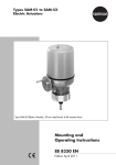
Type 3374 Electric Actuator
Fig. 1 · Type 3374 Actuator mounted on a Type 3535 Three-way Valve
Mounting and
Operating Instructions
EB 8331-1 EN
Edition July 2012
Contents
Contents
Page
1
1.1
1.2
Design and principle of operation. . . . . . . . . . . . . . . . . . . . 5
Additional equipment . . . . . . . . . . . . . . . . . . . . . . . . . . 5
Technical data . . . . . . . . . . . . . . . . . . . . . . . . . . . . . 6
2
2.1
2.2
Installation . . . . . . . . . . . . . . . . . . . . . . . . . . . . . . . 8
Mounting position. . . . . . . . . . . . . . . . . . . . . . . . . . . . 8
Attachment to the valve . . . . . . . . . . . . . . . . . . . . . . . . . 8
3
Electrical connections . . . . . . . . . . . . . . . . . . . . . . . . . 10
4
4.1
4.2
4.2.1
4.2.2
4.3
Operation and setting . . . . . .
Manual operation of the actuator.
Setting the additional equipment .
Limit contacts . . . . . . . . . .
Resistance transmitters . . . . . .
Setting the digital positioner . . .
.
.
.
.
.
.
.
.
.
.
.
.
.
.
.
.
.
.
.
.
.
.
.
.
.
.
.
.
.
.
.
.
.
.
.
.
.
.
.
.
.
.
12
12
12
12
12
14
5
5.1
5.1.1
5.1.2
5.2
5.3
5.4
5.4.1
5.4.2
Retrofitting additional electrical equipment . . . . . . . .
Installing the basic unit with new intermediate plate (index 6)
Limit contacts . . . . . . . . . . . . . . . . . . . . . . .
Resistance transmitters or digital positioner . . . . . . . . .
Limit contacts . . . . . . . . . . . . . . . . . . . . . . .
Resistance transmitters . . . . . . . . . . . . . . . . . . .
Digital positioner . . . . . . . . . . . . . . . . . . . . .
Calibrating the positioner . . . . . . . . . . . . . . . . .
Simplest method to calibrate the actuator . . . . . . . . . .
.
.
.
.
.
.
.
.
.
.
.
.
.
.
.
.
.
.
.
.
.
.
.
.
.
.
.
.
.
.
.
.
.
.
.
.
.
.
.
.
.
.
.
.
.
.
.
.
.
.
.
.
.
.
17
18
18
18
20
22
23
23
24
6
Dimensions in mm. . . . . . . . . . . . . . . . . . . . . . . . . . . 25
.
.
.
.
.
.
.
.
.
.
.
.
.
.
.
.
.
.
.
.
.
.
.
.
.
.
.
.
.
.
.
.
.
.
.
.
.
.
.
.
.
.
.
.
.
.
.
.
.
.
.
.
.
.
.
.
.
.
.
.
.
.
.
.
.
.
.
.
.
.
.
.
Note: Actuators with a CE marking fulfill the requirements of the Directives 94/9/EC and
89/336/EEC.
The Declaration of Conformity is available on request.
2
EB 8331-1 EN
Safety instructions
General safety instructions
For your own safety, follow these instructions concerning the mounting, start-up
and operation of the actuator:
4 The actuator is to be mounted, started up or operated only by trained and
4
4
4
experienced personnel familiar with the product.
According to these Mounting and Operating Instructions, trained personnel
refers to individuals who are able to judge the work they are assigned to
and recognize possible dangers due to their specialized training, their
knowledge and experience as well as their knowledge of the applicable
standards.
Any hazards that could be caused by the process medium, the operating
pressure, the signal pressure or by moving parts of the control valve are to
be prevented by means of the appropriate measures.
The actuators are designed for use in low-voltage installations.
For wiring and maintenance, you are required to observe the relevant safety
regulations. The actuator must be protected against unintentional
reconnection of the power supply.
Before wiring the actuator, disconnect it from the power supply.
To avoid damage to any equipment, the following also applies:
4 Proper transportation and storage are assumed.
EB 8331-1 EN
3
4
EB 8331-1 EN
Design and principle of operation
1
Design and principle of
operation
The Type 3374 Electric Actuator is used in
industrial plants as well as in heating, ventilation and air-conditioning systems.
The actuator is suitable for form-fit attachment to various SAMSON valve series, depending on the version with or without
fail-safe action. The actuators consist of a
reversible synchronous motor and a maintenance-free planetary gear with ball screw.
The synchronous motor is switched off by
torque-dependent switches when the final
positions are reached or in case of an overload.
1.1
Additional equipment
The actuators can be equipped with additional units, such as limit contacts and resistance transmitters, to influence the tasks of
control equipment. In addition, the actuator
can be equipped with a digital positioner for
processing standard signals in the range of
0/2 to 10 V or 0/4 to 20 mA.
Refer to section 5 for details on retrofitting
additional equipment.
The motion is transmitted to the actuator
stem by the gears and ball screw.
Actuator versions with integrated yoke are
primarily used for attachment to Series
V2001 Valves, Type 3260 (DN 65 to 150),
and Type 3214 (DN 65 to 250) Valves.
Actuator versions for central attachment using an M30 x 1.5 ring nut are preferably
combined with Series 240 Valves and
Type 3214 Valves (DN 125 to 150).
EB 8331-1 EN
5
Design and principle of operation
1.2
Technical data
Actuator
Type 3374
-10
Version with
-11
Yoke
Fail-safe action
-15
-21
-26
-31
-36
Ring nut
Yoke
Ring nut
Yoke
Ring nut
Without
Rated travel
mm
Transit time for
rated travel 3)
s
Stem extends
15
30
15
240/120
120/60
240/120
120/60
Transit time in case of fail-safe
action
s
–
12
2.5 kN
Stem extends or retracts
Thrust
Stem retracts
30
2 kN
Stem extends
0.5 kN
Stem retracts
207 V to 253 V, 50 Hz · 90 V to 121 V, 60 Hz
21.6 V to 27.6 V, 50 Hz
Power supply
Power consumption
Without positioner
With positioner
VA
10.5/16
12.5/18
7.5/13
9.5/15
Motor switch-off
Torque-dependent
Ambient temperature range
5 to 60 °C
Storage temperature range
–20 to +70 °C
Degree of protection
IP 54 according to EN 60529, (IP 65 with cable glands 1))
Suspended mounting position not approved
Overvoltage category
II according to EN 60664
Design and inspection
EN 61010 Edition 3.94
Class of protection
II according to EN 61140
Electromagnetic compatibility
Manual override
According to EN 61000-6-2, EN 61000-6-3 and EN 61326
Using hex wrench · Adjustment not possible after fail-safe action has been triggered
Manual adjustment of actuators with fail-safe action only possible when power
supply is connected (see also section 4.1)
Weight, approx. kg
3.2
Materials
3.3
3.9
4.0
3.5
3.6
Housing and cover made of plastic (PPO glass fiber reinforced)
Additional electrical equipment
Limit contact
Resistance transmitter
1)
2)
3)
6
Two travel-dependent, adjustable limit contacts, perm. load 250 V AC, 1 A
2)
0 to 1000 Ω, (0 to 900 Ω at rated travel) max. permissible current 1 mA
Cable glands M20 x 1.5 with metal nut, width across flats 23/24 mm
Not for version with positioner
Half the transit time possible for actuators with 50 Hz mains frequency
EB 8331-1 EN
Design and principle of operation
Digital positioner
Input signal 2)
1)
Range
Operating mode 1
Operating mode 2
Operating mode 3
4...20 mA, Ri = 0.05 kΩ
2...10 V, Ri = 10 kΩ
0...20 mA, Ri = 0.05 kΩ
0...10 V, Ri = 10 kΩ
As per settings 3)
Resolution
Position feedback
signal 4)
Range
4...20 mA, RB 0.2 ≤ kΩ
2...10 V, RB ≥ 5 kΩ
Resolution
0...20 mA, RB ≤ 0.2 kΩ
0...10 V, RB ≥ 5 kΩ
Adjustable
Setting
As per settings 3)
8 Bit
Increasing, actuator stem retracts or extends
as the input signal increases
Characteristic
Travel
10 Bit
As per settings 3)
6 to 19 mm at 15 mm rated travel
6 to 35 mm at 30 mm rated travel
Using travel calibration button
(1 mm each time the button is pressed)
As per settings 3)
using button
1 binary input
Electrically isolated, switching voltage 18 to 30 V DC, approx. 7 mA
1 binary output
Electrically isolated semiconductor contact, max. 45 V DC,
min. 3 V DC, max. 25 mA
Integrated interface for SAMSON
memory pen/PC
Data transmission including settings, operating status and alarms
Transfer protocol: SAMSON SSP protocol
Total delay time
Accuracy
Approx. 30 ms
≤ 2.5 %
without taking the dead band into account
1)
Maximum two current inputs may be switched in series
Maximum values ±50 mA or ±25 V
3)
SAMSON TROVIS-VIEW Operator Interface software, SAMSON memory pen
2)
EB 8331-1 EN
7
Installation
2
Installation
2.1
Mounting position
3.
Installation depends on the mounting position of the valve. However, do not install the
actuator suspended downwards.
Note: Manual override is only possible in
actuators with fail-safe action when the
power supply is connected (see section 4.1).
4.
5.
2.2
Attachment to the valve
tor nut (8) is reached. Secure position
with lock nut (9).
Place actuator onto valve bonnet (2.3)
and fasten with ring nut (7).
If necessary, retract actuator stem
slightly beforehand using the manual
override.
When the stem connector nut (8) fits
closely onto the actuator stem, attach
both stem connector clamps (4) and
screw tight.
Move actuator stem (3) to the end position (valve closed) using the manual
override or motor.
Align travel indicator scale (10) to the
middle of the stem connector (4) and
screw tight.
Series V2001 (DN 15 to 80),
Type 3260 Valve (DN 65 to 150) and
Type 3214 Valve (DN 65 to 100)
6.
1. Remove protective covers and unscrew
nut (6) from the valve.
2. Retract actuator stem slightly using the
manual override.
Place actuator with yoke onto the valve
and fasten with the nut (6, SW 36) using
a minimum tightening torque of
150 Nm.
3. When the plug stem (5) fits closely onto
the actuator stem (3), attach both stem
connector clamps (4) and fasten with
screws.
Type 3214 (DN 125 to 250)
Series 240
1. Push plug stem down to close the valve.
2. Turn stem connector nut (8) until a distance of x = 75 mm (x = 90 mm for
DN 100 and larger) between the top of
the yoke and the top of the stem connec-
8
EB 8331-1 EN
1. Place actuator onto the valve and secure
with the ring nut (7). If necessary, retract
actuator stem slightly beforehand using
the manual override.
2. When the plug stem fits closely onto the
actuator stem (3), attach both stem
connector clamps (4) and screw tight.
3. Move actuator stem (3) to the end position (valve closed) using the manual
override or motor.
4. Align travel indicator scale (10) to the
middle of the stem connector (4) and
screw tight.
Installation
Attachment to Series V2001,
Type 3260 (DN 65 to 150) and
Type 3214 (DN 65 to 100)
Attachment to Series 240
1
1
2.1
2.3
7
x
3
3
4
8
9
4
5
6
10
5
1
2.2
7
3
10
4
5
Attachment to Type 3214
(DN 125 to 250)
1
2.1
2.2
2.3
3
4
5
6
7
8
9
10
Actuator
Actuator yoke
Valve yoke
Bonnet
Actuator stem
Stem connector
Plug stem
Nut
Ring nut
Stem connector nut
Lock nut
Travel indicator scale
Fig. 2 · Attachment to the valve
EB 8331-1 EN
9
Electrical connections
3
Electrical connections
Upon installation of the electric cables, you are required to observe the
regulations concerning low-voltage
installations according to DIN VDE
0100 as well as the regulations of
your local power supplier.
Establish electrical connections as indicated
on the circuit diagram on the actuator cover
and as illustrated in Figs. 3 and 4.
A maximum of three cable glands can be attached to the housing for cable entries.
L
Ce
eL
Retracts
aL
Extends
Ce
–
+
N
N
L
aL
eL
N
N
L
Magnet in version with
fail-safe action
Limit contacts (optional)
41
44
42
51
54
Resistance transmitters (optional)
52
81
82
a
Fig. 3 · Terminal connections, version for three-point stepping signal
10
EB 8331-1 EN
83
91
e
92
e
93
a
Electrical connections
CAUTION!
4 Only connect to the mains power network when the power is switched off.
4 Only use power interruption devices
4 Particularly for 24 V/50 Hz actuators,
use wires with a sufficiently large
cross-section to guarantee that the permissible voltage tolerances are not exceeded.
which ensure that the power cannot be
switched on again unintentionally.
Limit contacts (optional)
41
44
42
51
54
52
Load, max. 25 mA
+
mA
31
_
32
V
+
V
_
mA
+
+
33
+
13
12
11
81
V
_
+
V _
82
83
84
N
L
N
L
Magnet in version with
fail-safe action
Position feedback
Input
Binary input
active when
voltage is
applied
Binary output
Power supply
Fig. 4 · Terminal connections, version with digital positioner
EB 8331-1 EN
11
Operation and setting
4
Operation and setting
4.2.1 Limit contacts
4.1
Manual operation of the
actuator
1. Use motor or manual override to move
the valve to the position where the
switching function is to be activated.
2. Use a hex wrench to turn spindle (2) for
the upper limit contact or spindle (3) for
the lower limit contact until the associated contact cam on the cam bracket (7)
triggers the switch contact of the upper
or lower microswitch (1).
To operate the manual override, place a
4 mm hex wrench on the red actuator shaft
located at the side of the housing. The hex
wrench is included in the scope of delivery.
It is attached to the bottom of the housing.
Manual override is only possible in actuators with fail-safe action when the power
supply is connected (terminals N and L).
Set the selector switch (2 in Fig. 6) of the actuator with positioner to the operating mode
0= .
4.2
Setting the additional
equipment
To access the additional equipment, unscrew
the four fixing screws on the cover using a
Pozidrive PZ2 screwdriver to provide
enough hold on the screw heads. Take off
the cover.
After completing the settings and establishing the electrical connection, refasten the
cover. To proceed, place back on the cover
and screw the cover screws in slightly to position the cover before tightening them properly.
Perform settings while the power is
switched on!
12
EB 8331-1 EN
4.2.2 Resistance transmitters
The gears of the potentiometers (12) and
(13) must be put onto their shafts to
correspond with the rated travel of the valve.
The rated travel inscription 'Nennhub 15'
(or B) or 'Nennhub 30' (or A) must be legible. If this is not the case, pull both potentiometer gears off their shafts and put them
back on again with the reverse side of the
wheel facing upwards, ensuring they are
aligned fairly flush with the potentiometer
shaft.
Zero point adjustment
1. Use motor or manual override to move
the valve to the desired end position.
2. Place a screwdriver on the slotted potentiometer shaft (12.1 and 13.1).
3. Calibrate resistance transmitter using the
connected ohmmeter correspondingly:
Actuator stem extends:
81/82 = 0 Ω ; 91/93 = 0 Ω ;
Actuator stem retracts:
81/83 = 0 Ω ; 91/92 = 0 Ω .
Operation and setting
Torque-dependent switch
Stem retracts
Metal tag
Stem extends
Rated travel inscription
12 12.1
e
13.1
a
N
B
en
n
15 hu
b
a
13
1
2
3
5
7
12
12.1
13
13.1
1
2
3
7
Microswitch
Spindle upwards
Spindle downwards
Intermediate gear
Cam bracket
Gear potentiometer 1
Potentiometer shaft
Gear potentiometer 2
Potentiometer shaft
5
Fig. 5 · Performing settings
EB 8331-1 EN
13
Operation and setting
4.3
Setting the digital positioner
In the actuator version with digital
positioner, the travel is calibrated automatically, allowing the travel (controlled variable
x) and the input signal (reference variable
w) of the positioner to be matched in the
best possible way. Additionally, the digital
positioner provides valve position feedback
for remote transmission.
Setting and start-up can be carried out using
four different operating modes. Operating
modes 1 and 2 work with set data stored in
the positioner's memory. The user only
needs to select the operating mode via the
selector switch (2) and press the button (4)
to start travel calibration.
Note: Setup with operating modes 3 and 0
=
can only be performed using a
SAMSON memory pen as the storage medium, or in connection with SAMSON's
TROVIS-VIEW Configuration and Operator
Interface software and a PC or bus system.
Setup with operating modes 3 and 0 =
is
described in Mounting and Operating Instructions EB 8331-2 EN.
Settings for operating modes 1 and 2
Increasing characteristic: actuator stem retracts or extends as the input signal increases.
After the actuator has been mounted on the
valve as described in section 2.2 and the
electrical connections have been established
as described in section 3, proceed as follows:
14
EB 8331-1 EN
1. Set selector switch (2) with the arrow
pointing to operating mode 0 =
(closed-loop operation switched off).
2. Check mounting position of the potentiometer gear (12).
The gear must be put onto the potentiometer
shaft to correspond with the rated travel of
the valve. The inscription Nennhub 15 or B
(for 6 to 19 mm travel) or Nennhub 30 or A
(for 6 to 35 mm travel) must be legible from
above on the associated gear side. If this is
not the case, pull the gear off the shaft and
put it back on again with the reverse side
facing upwards, allowing the intermediate
gear to engage properly.
NOTICE
Actuators with fail-safe action "Actuator
stem retracts" or "extends" are only designed for a rated travel of 15 mm. Do not
reposition the gear!
Make sure that the shaft of the potentiometer
(12.1) is adjusted correctly.
3. Switch on power supply and set the input signal to a current > 4 mA.
4. Set selector switch (2) with the arrow
pointing to operating mode 1 for 4 to
20 mA or 2 to 10 V input and alarm
signal, or set it to operating mode 2 for
0 to 20 mA or 0 to 10 V input and
alarm signal.
5. Press button (4) to start travel calibration.
Operation and setting
Press the button briefly to obtain a travel calibration for valve CLOSED when the actuator stem extends.
Direction of action: Increasing/increasing.
CAUTION!
The automatic travel calibration lasts
approximately twice as long as the
actuator's transit time. During this
period, the valve leaves its current
position. Calibrate the travel either
on the test bench or when the
shut-off valves in the plant are
closed.
Hold the button pressed for longer than
three seconds (indicated by switchover from
signal lamp 8 to signal lamp 9) to obtain a
travel calibration for valve CLOSED when
the actuator stem retracts.
Direction of action: Increasing/decreasing.
1
2
3
4
5
6
7
Operating mode 1
Selector switch
Operating mode2
Travel calibration button
Operating mode 0
Operating mode 3
Potentiometer counterclockwise or clockwise
8
Signal lamp
9
Signal lamp
10 Actuator stem extends
and retracts
11 Interface jack
12 Potentiometer gear
12.1 Potentiometer shaft
1 2
3
4
5
6
7
8
SAMSON
2
10
1
3
11
Stellungsregler
Positioner
Régulateur de position
Intermediate gear
Gear (12)
Position for 30 mm
rated travel (A)
Intermediate gear
Rated travel
inscription
Intermediate gear
12
B
Gear (12)
Position for 15 mm
rated travel (B)
9
12.1
Fig. 6 · Selector switch and position of potentiometer gears in version with digital positioner
EB 8331-1 EN
15
Operation and setting
After pressing the travel calibration button (4), the actuator stem first moves as far
as it will go to the valve's CLOSED position.
Calibration is in progress when both signal
lamps (8 and 9) are lit.
Travel calibration starts after the mounting
position of the potentiometer gear (12) has
been determined automatically. This is indicated by signal lamp (8) for 6 to 35 mm
travel and by signal lamp (9) for 6 to
19 mm travel.
When travel calibration starts, the lower signal lamp (9) blinks quickly for about 10 seconds. The actuator stem retracts as far as it
will go (maximum travel - valve OPEN).
Travel calibration is successfully completed
when the end position is reached. The actuator is in closed-loop operation. The actuator stem moves to the valve position determined by the input signal.
NOTICE
If one of the signal lamps starts to blink
slowly after the travel calibration button has
been pressed and the actuator stem has extended to the valve's CLOSED position, the
potentiometer shaft (12.1) has been wrongly
positioned. Remount it manually.
16
EB 8331-1 EN
Do not adjust the potentiometer before the
closed position is actually reached. This is
indicated by the associated, activated switch
on the board (Fig. 5 on page 13).
To proceed, adjust the shaft of the potentiometer (12.1) by turning it gradually clockwise or counterclockwise with a screwdriver
until the signal lamp stops blinking and is
constantly illuminated. Turn the screwdriver
counterclockwise if the upper signal lamp (8)
blinks, and clockwise if the lower signal
lamp (9) blinks, corresponding to the icons
(7). Travel calibration does not continue until
both signal lamps are illuminated at the
same time.
NOTICE
If both signal lamps start to blink simultaneously during travel calibration, interrupt
calibration by pressing the travel calibration
button (4) and check the mounting position
of the potentiometer gear (12) again.
If no travel motion can be determined during
calibration, e.g. due to a loose or missing
potentiometer gear, both signal lamps blink
in alternating sequence.
If this is the case, interrupt travel calibration
by pressing the button (4), correct the fault,
and restart calibration by pressing the button (4) again.
Retrofitting additional electrical equipment
Setting with limited travel range
Travel calibration is usually based on the
maximum travel of the valve.
If, however, the maximum possible travel is
to be limited to a smaller travel end value,
press the button (4) once at the start of calibration while the signal lamp blinks for
10 seconds. As a result, travel calibration
via the potentiometer gear with rated travel
15 or 30 is limited to 6 mm. Each time the
button is pressed, the travel range is increased by 1 mm.
If, for example, a valve designed for 15 mm
is to be operated with a limited travel range
of 10 mm, press the button (4) five times
during the 10 second time limit. The top signal lamp (8) flashes each time the key is
pressed.
Reporting defined events
At the binary output (terminal 83 and 84),
predefined events can be indicated (see
EB 8331-2 EN) during positioner operation
and transmitted to a control room.
5
Retrofitting additional
electrical equipment
CAUTION!
When installing electrical equipment, make
sure the power supply and the signal input
are disconnected. Only use power interruption devices which are protected against unintentional reconnection of the power supply.
Note: We recommend to apply a small
amount of lubricant (e.g. Vaseline) to the
spindles on the gear faces and to the sides
of the cogs.
The actuator can be subsequently equipped
with two limit contacts, two resistance transmitters or a digital positioner.
Depending on the actuator version used, the
actuator PCB needs to be replaced as well
(see sections 5.2, 5.3 and 5.4).
The actuator version is marked on the nameplate, e.g. Var.-ID 1063729.
When ordering additional electrical equipment from the manufacturer, include this
model number in the order.
To install the limit contacts, resistance transmitters or a digital positioner, the basic unit
(1400-8829) is required.
EB 8331-1 EN
17
Retrofitting additional electrical equipment
Old intermediate plate
The old intermediate plate model is marked
with less than six dots. The retrofitting of the
additional electrical equipment involves installing the spindle gear and intermediate
gear included in the basic unit
(1400-8829). The basic unit is not required
if a resistance transmitter or a digital
positioner is already installed in the actuator.
5.1
Installing the basic unit with
new intermediate plate
(index 6)
Note: This section only describes the additional mounting instructions for retrofitting
the additional electrical equipment with the
new intermediate plate (index 6). First follow
the instructions described in sections 5.2,
5.3 or 5.4
New intermediate plate (index 6)
The new intermediate plate with index 6 is
marked with six dots (••••••). The retrofitting of the additional electrical equipment
involves installing all the components included in the basic unit (1400-8829). See
Fig. 7 and section 5.1).
2 Spindle gear
5 Intermediate gear
10 Serrated ring (for 5)
14.1 Tension spring
14.2 Shim
14.3 Serrated ring (for
14.2)
5.1.1 Limit contacts
Fig. 8: Place tension spring (14.1) on
spindle 4 (4.4), ensuring that the long
wire of the spring rests on the spacer (9)
and on the intermediate gear (5), while
the short wire is located between spindle 3 (4.3) and spindle 4 (4.4).
Continue installation following instructions in step 8 on page 20.
5.1.2 Resistance transmitters or
digital positioner
Fig. 7 · Components included in basic unit
(1400-8829)
18
EB 8331-1 EN
Fig. 9: Place tension spring (14.1) on
spindle 4 (4.4), ensuring that the long
wire of the spring rests on the intermediate gear (5), while the short wire is located between spindle 3 (4.3) and spindle 4 (4.4). Place the shim (14.2) on
spindle 2 (4.2). Then attach the serrated
ring (14.3) and push it down as far as it
will go.
Continue installation following instructions in
step 4 on page 22 or page 23.
Retrofitting additional electrical equipment
4.2
4.1
4.1
4.2
4.3
4.4
5
9
14.1
5
4.3
"••••••"
Spindle 1
Spindle 2
Spindle 3
Spindle 4
Intermediate gear
Spacer
Tension spring
4.4
14.1
9
Fig. 8 · Installing the limit contacts
14.3
4.2
4.1
4.3
"••••••"
5
4.1
4.2
4.3
4.4
5
14.1
14.2
14.3
Spindle 1
Spindle 2
Spindle 3
Spindle 4
Intermediate gear
Tension spring
Shim
Serrated ring
4.4
14.1
14.2
Fig. 9 · Installing the resistance transmitters or digital positioner
EB 8331-1 EN
19
Retrofitting additional electrical equipment
5.2
Limit contacts
The retrofit kit (order no. 1402-0898) is required to install limit contacts.
Note: To install the limit contacts, the actuator stem must be in end position, i.e. the
stem must be either fully extended or fully
retracted. If necessary, move the stem to the
appropriate position using the manual override at the side.
1. Remove the fastening screws. Push the
actuator board (1) from its guiding to
the right. Slightly lift the board and continue pushing it further towards the cable
entry.
2. Clip the spindle gear (2) onto the sleeve
(3). Make sure the lateral latch is properly engaged in the groove of the sleeve.
3. Plug intermediate gear (5) onto the spindle (4). Place the serrated ring (10) on
top and push it down as far as it will go.
4. Plug both ready-assembled contact cams
(6) with the cog first onto the cam
bracket (7).
5. Push adjustment gears (8) onto their
spindles and fasten with one screw each.
Check whether the adjustment gears can
be turned easily. If not, slightly loosen
the screw again.
6. Turn both contact cams (6) as illustrated
in Fig. 10.1 corresponding with the position of the actuator stem on the cam
bracket (7).
7. Push the spacer (9) onto the spindle for
the cam bracket.
20
EB 8331-1 EN
Note: At this point, follow the instructions
described in section 5.1.1 on page 18 when
a new intermediate plate (with index 6) is
used.
8. Push the cam bracket with both cams
onto the spindle corresponding with the
position of the actuator stem as illustrated in Fig. 10.2. Make sure that the
outermost cog of the cam bracket (7) engages in the gearwheel of the intermediate gear (5). In addition, the adjustment
gears (8) must engage properly in the
corresponding gears of the contact cams
(6).
9. Secure the cam bracket (7) and intermediate gear (5) with the serrated ring
(10), pushing the ring down as far as it
will go.
10. Position the terminal board (11) at the
base of the support at a 45° angle
(approx.) with the switches facing towards the gears. Push the upper end of
the terminal board towards the gears
until the board is in a vertical position
and properly engaged in the support.
11. Push the actuator board (1) back into its
guiding. Make sure that the gears are
properly engaged. Fasten the board using screws.
4 Adjust limit contacts as described in section 4.2.1.
Retrofitting additional electrical equipment
1
2
3
4
5
6
7
8
Actuator board
Spindle gear
Sleeve
Spindle
Intermediate gear
Contact cam
Cam bracket
Adjustment gear
9
10
11
Spacer
Serrated ring
Terminal board with
microswitches
12 Gear in version
with resistance transmitter
10.1 Position of the contact cams (6) on the cam bracket (7)
8
9
5
4
3
2
1
7
12
6
6
For actuator stem
retracts
extends
10.2 Position of the cam bracket (7)
5
7
11
12
10
B
8
7
For actuator stem retracts
For actuator stem extends
B
5
2
Fig. 10 · Retrofitting limit contacts, in this example model 3374-11000002000, version with resistance transmitters
EB 8331-1 EN
21
Retrofitting additional electrical equipment
5.3
Resistance transmitters
Actuators with a digital positioner cannot be
equipped with resistance transmitters.
To install the resistance transmitters, an actuator board with the appropriate potentiometers and gears (12 and 13) is required.
1. Remove the fastening screws. Push the
actuator board (1) from its guiding to
the right. Take out the board and replace it with a board with potentiometers.
2. Clip the spindle gear (2) onto the sleeve
(3) as illustrated in Fig. 10.1 (top). Make
sure the lateral latch is properly engaged in the groove of the sleeve.
3. Plug intermediate gear (5) onto the spindle 1 (4.1). Place the serrated ring (10)
on top and push it down as far as it will
go.
1
2
5
10
Actuator board 10
12
Contact cam
Intermediate gear 13
5
2
Serrated ring
Gear potentiometer 1
Gear potentiometer 2
13
12
Fig. 11 · Version with resistance transmitter
22
EB 8331-1 EN
1
Note: At this point, follow the instructions
described in section 5.1.2 on page 18 when
a new intermediate plate (with index 6) is
used.
4. The potentiometer gears (12 and 13)
with retaining rings must be put onto
their shafts corresponding with the rated
travel of the valve. The rated travel inscription 'Nennhub 15' or B (on the upper side with the retaining ring) or
'Nennhub 30' or A (lower side) must be
legible from above (also see Figs. 5 and
6).
5. Push the actuator board back into its
guiding. Make sure that the gears are
properly engaged. Fasten the board using screws.
4 Adjust the resistance transmitters as described in section 4.2.2.
Retrofitting additional electrical equipment
5.4
Digital positioner
To install a positioner, a corresponding actuator PCB and the TROVIS-VIEW software
as well as a connecting cable (1400-7699)
are necessary.
5. Push the actuator board (1) back into its
guiding. Make sure that the gears are
properly engaged. Fasten the board using screws.
5.4.1 Calibrating the positioner
Note: Actuators with a digital positioner
cannot be equipped with resistance transmitters.
5
6
7
8
10
12
1. Remove the fastening screws. Push the
actuator board (1) from its guiding to
the right. Take out the board and replace it with a board with positioner.
2. Clip the spindle gear (2) onto the sleeve
(3) as illustrated at the top of Fig. 12
(top). Make sure the lateral latch is properly engaged in the groove of the sleeve.
3. Plug intermediate gear (5) onto the spindle (4). Place the serrated ring (10) on
top and push it down as far as it will go.
Note: At this point, follow the instructions
described in section 5.1.2 on page 18 when
a new intermediate plate (index 6) is used.
4. The gear (12) on the feedback potentiometer, which is equipped with a retaining ring, must be put onto its shaft corresponding with the rated travel of the
valve. The rated travel inscription
'Nennhub 15' or B (on the upper side
with the retaining ring) or 'Nennhub 30'
or A (lower side) must be legible from
above (also see Figs. 5 and 6).
8
Intermediate gear
Contact cam
Cam bracket
Adjustment gears
Serrated ring
Gear feedback potentiometer
7
5
10
12
Fig. 12 · Version with positioner
without (top) and with (bottom) limit contacts
EB 8331-1 EN
23
Retrofitting additional electrical equipment
To calibrate the positioner, proceed as described in section 4 of EB 8331-2 EN.
5.4.2 Simplest method to calibrate
the actuator
If tools, such as the TROVIS-VIEW software
or a PC, are not available for calibration of
the actuator and the actuator operation with
maximum precision is not necessary, the
simplest calibration method can be performed as follows:
1. Position the selector switch (2) to operating mode 0 =
.
2. Press down the travel calibration button
(5) for at least 15 seconds until both signal lamps light up.
3. Release the button to start calibration.
The actuator stem extends until the
torque-dependent switches switch off the
actuator.
The position of the potentiometer is
checked.
4. Re-adjust the potentiometer, if necessary,
while observing the signal lamps. Refer
to the description given on page 14 of
EB 8331-2 EN.
After adjusting the potentiometer, the
calibration of the actuator is continued.
24
EB 8331-1 EN
4 Mount the actuator on the valve and set
the positioner as described in section
4.3 of these instructions.
Dimensions in mm
Dimensions in mm
Version with yoke
Version with ring nut
193
120
30 (15)
Stem connector
90 (75)
15 (30)
294
204
60
50
6
EB 8331-1 EN
25
26
EB 8331-1 EN
EB 8331-1 EN
27
EB 8331-1 EN
2014-05
SAMSON AG · MESS- UND REGELTECHNIK
Weismüllerstraße 3 · 60314 Frankfurt am Main, Germany
Phone: +49 69 4009-0 · Fax: +49 69 4009-1507
Internet: http://www.samson.de