1
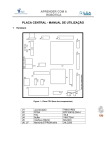
Operating Instructions Update SMV 04 PSG Plastic Service GmbH P.O. Box 42 01 62 68280 Mannheim Germany Phone +49 621 7162 0 Fax +49 621 7162 162 www.psg-online.de [email protected] Rev. 0.1.3 11/2009 PSG Plastic Service GmbH Operating Instructions SMV 04 Update 1 2 Installation.............................................................................................................................................................2 Appendix...............................................................................................................................................................7 2.1 Version History...............................................................................................................................................7 Right to technical changes reserved Rev. 0.1.3 1 2 Chapter 1 Installation 1 Installation Install the Atmel Software on directory \Atmel\Setup.exe on the attached CD-ROM. Step 1: Switch off 230 V voltage Remove the two fuses F1 and F2 on the SMV 04 module. Step 2: DIP switch setting for CAN current interface CAN STI Put DIP switch 5 to ON. The sending of control information to the SMV 04 modules is interrupted. Step 3: Attachment of program adapter AT-COM The SMV 04 module exists in two models Revision 1 - without LEDs Revision 2 - with LEDs for status indication of controller outputs The program adapter is attached to the appropriate SMV 04 model as shown in the following two pictures. Figure 1 SMV 04 without LEDs Figure 2 SMV 04 with LEDs Right to technical changes reserved Rev. 0.1.3 PSG Plastic Service GmbH Operating Instructions SMV 04 Update Step 4: Start update software for SMV 04 Controller Start update software Flip Use Flip 2.4.2 Step 5: Selection of controller type Select type AT89C51ED2 Right to technical changes reserved Rev. 0.1.3 3 4 Chapter 1 Installation Step 6: HEX file load menu Step 7: File selection SMV04.HEX File on CD-ROM Right to technical changes reserved Rev. 0.1.3 PSG Plastic Service GmbH Operating Instructions SMV 04 Update Step 8: Select communication settings Step 9: Select serial interface Select interface type RS232 Select COMPORT (dependant on PC, e.g. COM1) Select baud rate 38400 (or baud rate 19200) Press RESET at AT-COM adapter. Establish interface connection pressing the button Connect Right to technical changes reserved Rev. 0.1.3 5 6 Chapter 1 Installation After a successful connection build-up all processing steps are labelled with a check mark. Start of processing by clicking on Run If processing aborts, Check controller type (T89C51RD2) and change it if necessary. Start again with Run. If controller type is ok deactivate “Blank Check”. Start again with Run. Step 10: Completion of programming View after successful programming Software start after remove of program adapter AT-COM. After successful update of all SMV 04 modules connected to CAN STI, put DIP switch 5 to OFF. Step 11: Potentiometer measurement of end position After completion of programming the potentiometer measurement of end position has to be done according to the instructions of data sheet “Serve valve module SMV 04”. Recommendation: After completion of all steps put a label with firmware version onto SMV 04 module. Right to technical changes reserved Rev. 0.1.3 PSG Plastic Service GmbH Operating Instructions SMV 04 Update 2 Appendix 2.1 Version History Version Date Changes 0.1.3 11/12/2009 0.1.2 0.1.1 0.1 05.10.2005 07.07.2005 17.06.2005 In detail the following amendments were made: Installation step 1/2 changed Flip 2.4.2 amended Controller type changed (T89C51RD2 -> AT89C51ED2) Reset before Connect amended Feasible baud rate 19200 Serial interface process abort supplemented First release Right to technical changes reserved Rev. 0.1.3 7