1
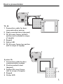
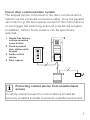
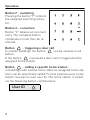
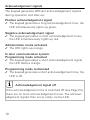
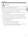
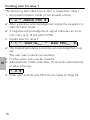
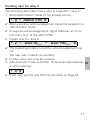
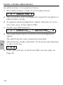
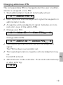
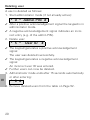
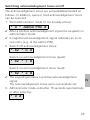
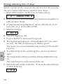
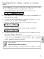
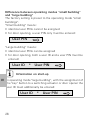
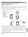
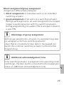
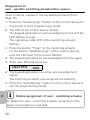
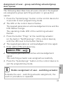
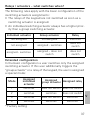
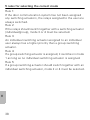
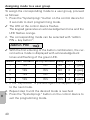
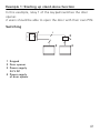
Operating Instructions
Keypad
2605 ..
Contents
Device description ............................................................. 4
Device presentation ........................................................... 5
Areas of application ........................................................... 6
Operation ........................................................................... 8
Acknowledgement signals ............................................... 10
Start-up sequence ............................................................ 11
Connection terminals ....................................................... 12
Installation ...................................................................... 13
What is an administrator, a user? ..................................... 14
Creating first administrator ............................................... 15
Creating user for relay 1 ................................................... 16
Creating user for relay 2 ................................................... 17
Create a further administrator .......................................... 18
Changing admin/user PIN................................................. 19
Deleting user.................................................................... 20
Deleting administrator ...................................................... 21
Switching button illumination on/off ............................... 22
Switching acknowledgement tones on/off....................... 23
Setting switching time of relays ....................................... 24
Resetting to factory settings-selection of operating mode 25
Keypad in door communication system ............................ 27
Connection to door communication system ..................... 28
Assignment of user - specific switching actuator/
door opener ..................................................................... 30
Assignment of user-group switching actuator/
door opener ..................................................................... 31
2
Assigning function button "F" to a switching actuator ...... 32
Assigning bell button to a home station ........................... 33
Specifically assigning bell button to a home station ......... 34
Assigning bell button to a switching actuator................... 35
Specifically assigning bell button to a switching
actuator ........................................................................... 36
Relays / actuators – what switches when? ....................... 37
5 rules for selecting the correct mode .............................. 38
Assigning mode to an individual user ............................... 39
Assigning mode to a user group ...................................... 40
Examples
Example 1: Start-up stand-alone function ......................... 41
Example 2: Start-up multi-family house with
door communication system ............................................ 43
Example 3: Start-up single-family house with
door communication system ............................................ 47
Example 4: Integrating in door communication
system without speech function....................................... 50
Removal alarm ................................................................. 51
Table for start-up documentation ..................................... 52
Procedure with loss of admin PIN .................................... 53
Technical data ................................................................. 54
Warranty ......................................................................... 55
3
Device description
The keypad provides convenient and secure access control
for inside and outside areas. The keypad opens the door
when a personal code is entered. Capacitive switching technology enables operation by a light touch of the finger. The
keypad can be used as a stand-alone function, e.g. at individual doors or gates. It can also be integrated into the Gira door
communication system. No additional control components
are required here.
Easy start-up without a PC or programming software is possible via direct configuration at the device.
The two integrated zero-voltage two-way switch relays can
be assigned to different codes. Thus it is possible to carry out
two different switching processes, e.g. code 1 for door opening and code 2 for switching the outside light via a remotecontrol switch. The keypad can manage up to 255 codes
(incl. admin code and release code).
The keypad is installed indoors (IP 20) in conjunction with
System 55 cover frames and outdoors (IP 44) with TX_44
cover frames.
4
Device presentation
1
2
3
TX_44
1 Connection cable for door
communication system
2 Flush-mounted insert (keypad)
3 TX_44 cover frame, bottom
section (not included in scope
of supply)
4 Keypad
5 Status LED
6 TX_44 cover frame top section
(not in scope of supply)
1
2
3
4
5
6
7
8
9
*
0
#
4
F
6
5
C
1
2
System 55
1 Connection cable for door
communication system
2 Flush-mounted insert
(keypad)
3 System 55 cover frame
(not in scope of supply)
4 Keypad
5 Status LED
3
4
5
5
Areas of application
Use as individual device
In this case the existing zero-voltage relay contacts within
the flush-mounted insert are used, e.g. for a door opener
with own power supply.
i
Use as individual device not in
safety-relevant areas
Not recommended for opening of outside doors especially
in safety-relevant areas, as door may be opened with expansion of keypad via bridging of open contacts.
1
2
3
4
5
6
7
8
9
*
0
#
F
1
2
2
C
2
2
3
1 Keypad
2 Door opener
3 Power supply
24 V DC
4 Power supply
of door opener
6
4
Use in door communication system
The keypad can be connected to the door communication
system via the enclosed connection cable. Thus the keypad
can control e.g. the door opener contact of the control device
or can trigger the switching action of a switching actuator.
In addition, further home stations can be specifically
selected.
1 Hands-free feature
surface-mounted
home station
2 Flush-mounted
door station with
keypad
3 Audio control
device
4 Door opener
2
1
1
2
3
4
5
6
7
8
9
*
0
#
F
C
2
2
2
3
i
4
Protecting control device from unauthorised
access
In safety-relevant areas the control device should be
securely installed (locked) to prevent unauthorised access.
7
Operation
Button F - switching
Pressing the button "F" controls
the assigned switching actuator.
Button C - correction
Button "C" deletes an incorrect
entry. The complete button
combination must then be reentered.
Button
- triggering a door call
In smaller buildings the button
can be used as a call
button.
If the button
is pressed a door call is triggered at the
assigned home station.
Button
- calling a specific home station
In buildings with several home stations, assigned home stations can be specifically called. For this purpose every home
station receives its own user ID. The home station is called
via the following button combinations:
User ID
8
Button
- open door
The door is opened via the following button combinations:
In operating mode "small buildings":
User PIN
In operating mode "large buildings" (see Page 25):
User ID
i
*
User PIN
Acknowledgement tones can be switched off
Acknowledgement tones occurring during operation can be
switched off (see Page 23).
9
Acknowledgement signals
The keypad generates different acknowledgement signals
during operation and start-up:
Positive acknowledgement signal
✓ The keypad generates a long acknowledgement tone, the
LED simultaneously lights up green.
Negative acknowledgement signal
✓ The keypad generates 3 short acknowledgement tones,
the LED simultaneously lights up red.
Administrator mode activated
✓ The LED lights up orange.
In door communication system:
Programming mode activated
✓ The keypad generates a short acknowledgement signal,
the LED flashes orange.
Programming mode terminated
✓ The keypad generates a short acknowledgement tone, the
LED is off.
i
Acknowledgement signal off
If the acknowledgement tone is switched off (see Page 23),
there are no more acknowledgement tones. The acknowledgement signals then occur solely via the LED.
10
Start-up sequence
For start-up the keypad, the following steps must be implemented in the order shown below:
I.
Install keypad (from Page 12)
LED flashes green
I
II. Create first administrator (Page 15)
* 3 * Admin IDNew * Admin PINNew #
III. Create user for relays 1/2 (from Page 16)
* 1/2 *
User IDNew
*
User PIN New
#
II
III
IV. Carry out configurations to keypad
(from Page 19)
IV
V. Use in door communication system
Assigning door opener/switching actuators (from
p. 27)
V
11
Connection terminals
I
13
GND
+24V DC
13
Relay 1
Service
Relay 2
Power supply
Door communication
12
1
Relay 1 N.O. (NO contact)
2
Relay 1 COM
3
Relay 1 N.C. (NC contact)
4
not used
5
not used
6
GND
7
Relay 2 N.O. (NO contact)
8
Relay 2 COM
9
Relay 2 N.C. (NC contact)
10
GND
11
+ 24 V DC
12
not used
13
6-pole slot
door communication system
Installation
Attention
Installation and mounting of electrical devices may only be
carried out by a qualified electrician.
The keypad is connected via both detachable terminal strips
and mounted in a 58 mm flush-mounted box.
1. Pull off required terminal strip and connect according to
terminal figuration.
2. Attach terminal strip to the flush-mounted insert again.
3. Install flush-mounted insert into flush-mounted box.
4. Install cover frame and attach cover plate of the keypad.
✓ 10 seconds after operating voltage is applied, the LED of
the keypad flashes green.
5. Start-up the keypad:
• first create an administrator (Page 15),
• then create the user (from Page 16),
• then if necessary assign switching actuator functions
or door opener functions (from Page 30).
13
I
What is an administrator, a user?
For starting up, an administrator must be created. Users are
created for operation.
Administrator
An administrator always consists of an admin ID and an
admin PIN
• Admin ID:
1 to 6-digit
• Admin PIN: 1 to 32-digit (for configuration of
keypad)
User
II A user consists of a user ID and a user PIN
• User ID:
• User PIN:
i
1 to 6-digit (for door call functions)
1 to 32-digit (for door opening
functions or switching actions).
Information about IDs and PINs
The allocation of identical IDs is not possible. If an administrator receives ID 1, there cannot be a user with the ID 1.
The allocation of identical PINs is only possible in operating
mode "large buildings". Further information about operating
modes "small buildings" / "large buildings" on p. 26
14
Creating first administrator
Before first start-up, an administrator must be created. If no
administrator has been created, the LED of the keypad
flashes green.
i
Admin ID and admin PIN
Admin ID and admin PIN cannot be used for switching
actions, e.g. for opening of a door.
Create administrator:
✓ LED flashes green.
1. Create new administrator:
II
* 3 * Admin IDNew * Admin PINNew #
✓ The keypad generates a positive acknowledgement signal:
An administrator was created successfully.
The keypad is now in administrator mode.
2. Enter administrator with ID and PIN into the table on
Page 52.
i
Correct operating mode selected?
Upon delivery the operating mode "small buildings" is preset. This means that identical PINs cannot be assigned. Further information about operating modes "small buildings" /
"large buildings" on Page 26.
15
Creating user for relay 1
The following describes how a user is created for relay 1.
1. Start administrator mode (if not already active):
* 0 * Admin PIN #
✓ After a positive acknowledgement signal the keypad is in
administrator mode.
✓ A negative acknowledgement signal indicates an incorrect entry (e.g. of the admin PIN).
2. Create user for relay 1:
* 1 *
User IDNew
*
User PINNew
#
✓ The keypad generates a positive acknowledgement sig-
nal:
The user was created successfully.
✓ Further users can now be created.
III 3. Administrator mode ends after 15 seconds automatically
or after entering:
* 0 #
4. Enter user with ID and PIN into the table on Page 52.
16
Creating user for relay 2
The following describes how a user is created for relay 2.
1. Start administrator mode (if not already active):
* 0 * Admin PIN #
✓ After a positive acknowledgement signal the keypad is in
administrator mode.
✓ A negative acknowledgement signal indicates an incorrect entry (e.g. of the admin PIN).
2. Create user for relay 2:
* 2 *
User IDNew
*
User PINNew
#
✓ The keypad generates a positive acknowledgement sig-
nal:
The user was created successfully.
✓ Further users can now be created.
3. Administrator mode ends after 15 seconds automatically III
or after entering:
* 0 #
4. Enter user with ID and PIN into the table on Page 52.
17
Create a further administrator
An administrator is created as follows:
1. Start administrator mode (if not already active):
* 0 * Admin PIN #
✓ After a positive acknowledgement signal the keypad is in
administrator mode.
✓ A negative acknowledgement signal indicates an incorrect entry (e.g. of the admin PIN).
2. Create new administrator:
* 3 * Admin IDNew * Admin PINNew #
✓ The keypad generates a positive acknowledgement
signal:
The administrator was created successfully.
3. Administrator mode ends after 15 seconds automatically
or after entering:
III
* 0 #
4. Enter administrator with ID and PIN into the table on
Page 52.
18
Changing admin/user PIN
The corresponding PIN is changed when the user or administrator is assigned a new PIN:
1. Start administrator mode (if not already active):
* 0 * Admin PIN #
✓ After a positive acknowledgement signal the keypad is in
administrator mode.
✓ A negative acknowledgement signal indicates an incorrect entry (e.g. of the admin PIN).
2. Change user PIN:
* 4 *
User ID
*
User PINNew
#
Change admin PIN:
* 4 * Admin ID * Admin PINNew #
✓ The keypad generates a positive acknowledgement
signal:
The PIN has been successfully set.
✓ The keypad generates a negative acknowledgement signal:
IV
Invalid ID entered.
3. Administrator mode ends after 15 seconds automatically
or after entering:
* 0 #
19
Deleting user
A user is deleted as follows:
1. Start administrator mode (if not already active):
* 0 * Admin PIN #
✓ After a positive acknowledgement signal the keypad is in
administrator mode.
✓ A negative acknowledgement signal indicates an incorrect entry (e.g. of the admin PIN).
2. Delete user:
* 5 *
User ID
#
✓ The keypad generates a positive acknowledgement
IV
signal:
The user was deleted successfully.
✓ The keypad generates a negative acknowledgement
signal:
An incorrect user ID was entered.
✓ Further users can now be deleted.
3. Administrator mode ends after 15 seconds automatically
or after entering:
* 0 #
4. Remove deleted users from the table on Page 52 .
20
Deleting administrator
An administrator is deleted as follows:
1. Start administrator mode (if not already active):
* 0 * Admin PIN #
✓ After a positive acknowledgement signal the keypad is in
administrator mode.
✓ A negative acknowledgement signal indicates an incorrect entry (e.g. of the admin PIN).
2. Delete administrator:
* 5 * Admin ID #
✓ The keypad generates a positive acknowledgement signal: The administrator was deleted successfully.
✓ The keypad generates a negative acknowledgement signal: An incorrect admin ID was entered.
✓ Further administrators can now be deleted.
3. Administrator mode ends after 15 seconds automatically
or after entering: * 0 #
i
IV
Last admin cannot be deleted
The last remaining administrator can only be deleted via
resetting to factory settings (Page 25).
4. Remove deleted administrators from the table on
Page 52 .
21
Switching button illumination on/off
The illumination of the keypad can be switched as follows:
1. Start administrator mode (if not already active):
* 0 * Admin PIN #
✓ After a positive acknowledgement signal the keypad is in
administrator mode.
✓ A negative acknowledgement signal indicates an incorrect entry (e.g. of the admin PIN).
2. Switch on illumination:
* 61 * 1 #
Switch off illumination:
* 61 * 0 #
✓ The keypad generates a positive acknowledgement
signal:
The illumination was switched on/off successfully.
3. Administrator mode ends after 15 seconds automatically
or after entering:
* 0 #
IV
22
Switching acknowledegment tones on/off
The acknowledgement tones are activated/deactivated as
follows. In addition, quiet or loud acknowledgement tones
can be selected.
1. Start administrator mode (if not already active):
* 0 * Admin PIN #
✓ After a positive acknowledgement signal the keypad is in
administrator mode.
✓ A negative acknowledgement signal indicates an incorrect entry (e.g. of the admin PIN).
2. Switch off acknowledgement tones:
* 62 * 0 #
Switch on acknowledgement tones (quiet):
* 62 * 1 #
Switch on acknowledgement tones (loud):
* 62 * 2 #
✓ The keypad generates a positive acknowledgement
IV
signal:
The acknowledgement tones were successfully set.
3. Administrator mode ends after 15 seconds automatically
or after entering:
* 0 #
23
Setting switching time of relays
Switching time of the relays can be set from 3 to 30 seconds.
The set contact hold time is valid for both relays.
1. Start administrator mode (if not already active):
* 0 * Admin PIN #
✓ After a positive acknowledgement signal the keypad is in
administrator mode.
✓ A negative acknowledgement signal indicates an incorrect entry (e.g. of the admin PIN).
2. Start procedure:
* 63 #
✓ The LED lights up red.
3. Press a button to start switching time.
✓ The keypad generates an acknowledgement tone every
second, the LED simultaneously flashes green.
The relays are not activated during setting of the switching time.
4. To end setting of the switching time, press any button
again.
IV ✓ The keypad generates a positive acknowledgement signal:
The switching time was successfully set.
5. Administrator mode ends after 15 seconds automatically
or after entering:
* 0 #
24
Resetting to factory settings - selection of operating
mode
The keypad can be reset to the state of delivery. In this case,
all user and administrator assignments are lost.
1. Start administrator mode (if not already active):
* 0 * Admin PIN #
✓ After a positive acknowledgement signal the keypad is in
administrator mode.
✓ A negative acknowledgement signal indicates an incorrect entry (e.g. of the admin PIN).
2. Factory setting: operating mode "small buildings":
* 9 * 1230 #
Factory setting: operating mode "large buildings":
* 9 * 1231 #
✓ The keypad generates a positive acknowledgement sig-
nal, then flashes green/red.
The LED then flashes green, all keypad settings have been
reset, all users and administrators deleted. The keypad is
IV
in the selected operating mode.
i
Important!
Administrator also deleted
Before reprogramming, an administrator must be created.
25
Difference between operating modes "small building"
and "large building"
The factory setting is preset to the operating mode "small
buildings".
"Small building" means:
• identical user PINs cannot be assigned
• for door opening, a user PIN only must be entered:
User PIN
"Large building" means:
• identical user PINs can be assigned
• for door opening, both a user ID and a user PIN must be
entered:
User ID
i
*
User PIN
Information on start-up
IV In operating mode "large building", with the assignment of
the "key" button to a switching actuator or door opener the
user ID must additionally be entered:
User ID
26
*
User PIN
Integration in the door communication system
i
Create administrator and user
before start-up
Before before start-up the keypad in the door communication system, the corresponding administrators and users
must be created (from Page 15).
1 Surface-mounted home
station
2 Door station with
keypad
3 Switching
actuator
4 Control device
5 Door opener
2
1
1
2
3
4
5
6
7
8
9
*
0
#
F
C
2
2
3
2
2
4
5
The keypad can be connected to the Gira flush-mounted door
stations and to the built-in loudspeaker. The keypad can control up to 16 switching actuators (8 group actuators + 8 individual switching actuators) and the door opener function. In
V
addition, home stations can be called directly from the door
communication system.
Full functionality of the switching actuators from index
I04.
27
Connection to door communication system
The keypad is connected to a door communication bus coupler or call button insert of the Gira door communication system with the accompanying connection cable.
1
2
1 2 3 4 5 6
7 8 9 10 1 112
ZV
1 Keypad
2 Door communication bus coupler
BUS
Power supply for the keypad is possible via the door communication bus. In this case, jumpers between ZV and BUS
must be attached to the bus coupler of the door station.
i
Firstly, start up
door communication system
Before programming of the keypad is begun, the door
communication system must be started up.
V
28
Direct assignment/group assignment
Assignment differentiates between:
• direct assignment of individual users to an individual
switching actuator
• group assignment of all users to a switching actuator.
With group assignments, all users assigned to the keypad
trigger a switching action with the switching actuator.
During programming, the admin PIN is entered instead of
a user PIN.
i
Advantage of group assignment
With group assignments, all users in a programming step
are assigned a common switching actuator.
Users that are created at a later date in the keypad can
switch this common switching actuator without further
programming.
i
Additional acknowledgement tone
If the switching actuator is assigned in the operating mode
"switching", the door station connected to the keypad generates an additional acknowledgement tone.
29
V
Assignment of
user - specific switching actuator/door opener
Users must be created in the keypad beforehand (from
Page 16).
1. Press the "Systemprogr." button on the control device for
3 seconds to start programming mode.
✓ The LED at the control device flashes.
The keypad generates an acknowledgement tone and the
LED flashes orange.
The operating mode LED of the switching actuator
flashes.
2. Press the button "Progr." at the switching actuator
(or the button "Türöffnerprogr." of the control device),
until the LED next to the button flashes.
✓ The keypad generates an acknowledgement tone again.
3. Enter user PIN and press key.
User PIN
✓ The keypad generates a positive acknowledgement
signal:
The switching actuator was assigned successfully.
4. Press the "Systemprogr." button on the control device to
exit the programming mode.
i
V
Delete assignment of user - switching actuator
To delete the user - switching actuator assignment, the
teach-in procedure is repeated.
30
Assignment of user - group switching actuator/group
door opener
The following describes how all users stored in the keypad
are assigned a group switching actuator or group door
opener.
1. Press the "Systemprogr." button on the control device for
3 seconds to start programming mode.
✓ The LED at the control device flashes.
The keypad generates an acknowledgement tone and the
LED flashes orange.
The operating mode LED of the switching actuator
flashes.
2. Press the button "Progr." at the switching actuator
(or the button "Türöffnerprogr." of the control device),
until the LED next to the button flashes.
✓ The keypad generates an acknowledgement tone again.
3. Enter admin PIN and press key.
Admin PIN
✓ The keypad generates a positive acknowledgement
signal:
The switching actuator was assigned successfully.
4. Press the "Systemprogr." button on the control device to
exit the programming mode.
i
Delete assignment of user - switching actuator
To delete the user - switching actuator assignment, the
teach-in procedure is repeated.
31
V
Assigning function button "F" to a switching actuator
1. Press the "Systemprogr." button on the control device for
3 seconds to start programming mode.
✓ The LED at the control device flashes.
The keypad generates an acknowledgement tone and the
LED flashes orange.
The operating mode LED of the switching actuator
flashes.
2. Press the "Progr." button on the switching actuator until
the LED next to the button flashes.
✓ The keypad generates an acknowledgement tone again.
3. Press function button "F".
F
✓ The keypad generates a positive acknowledgement
signal:
The switching actuator was assigned successfully.
4. Press the "Systemprogr." button on the control device to
exit the programming mode.
i
Delete assignment of button "F" - switching actuator
To delete the button "F" - switching actuator assignment,
the teach-in procedure is repeated.
V
32
Assigning bell button to a home station
1. Press the "Systemprogr." button on the control device for
3 seconds to start programming mode.
✓ The LED at the control device flashes.
The keypad generates an acknowledgement tone and the
LED flashes orange.
2. Press "Bell" button.
✓ The keypad lights up orange, the door station generates a
short and a long acknowledgement tone, the keypad
flashes orange.
3. Press the button "Light" on the home station for
3 seconds until a short acknowledgement tone is heard.
✓ A long acknowledgement tone confirms successful
assignment.
✓ Three short acknowledgement tones indicate faulty
assignment. The memory of the home station may
already be occupied.
4. Press the "Systemprogr." button on the control device to
exit the programming mode.
i
Assign several home stations per work step
Up to 20 code assignments can be temporarily stored per
step. If more than 20 home stations are to be assigned, the
first 20 codes must first be entered and then assigned to
the home stations. The remaining codes can then be
assigned.
33
V
Specifically assigning a bell button to a home station
i
Create user
To specifically assign a bell button to a home station, a user
must be created in the keypad for this home station
(Page 16).
1. Press the "Systemprogr." button on the control device for
3 seconds to start programming mode.
✓ The LED at the control device flashes.
The keypad generates an acknowledgement tone and the
LED flashes orange.
2. User ID + press "Bell" button.
User ID
✓ The keypad lights up orange,
3.
✓
✓
V
4.
34
the door station generates a short and a long acknowledgement tone, the keypad flashes orange.
Press the button "Light" on the home station for
3 seconds until a short acknowledgement tone is heard.
A long acknowledgement tone confirms successful
assignment.
Three short acknowledgement tones indicate faulty
assignment. The memory of the home station may
already be occupied.
Press the "Systemprogr." button on the control device to
exit the programming mode.
Assigning bell button to a switching actuator
With parallel assignment of the bell button to a switching
actuator and a home station, first assign the switching actuator, then assign the home station.
1. Press the "Systemprogr." button on the control device for
3 seconds to start programming mode.
✓ The LED at the control device flashes.
The keypad generates an acknowledgement tone and the
LED flashes orange.
The operating mode LED of the switching actuator
flashes.
2. Press the "Progr." button on the switching actuator until
the LED next to the button flashes.
✓ The keypad generates an acknowledgement tone again.
3. Press "Bell" button.
✓ The keypad generates a positive acknowledgement
signal:
The switching actuator was assigned successfully.
4. Press the "Systemprogr." button on the control device to
exit the programming mode.
i
Delete assignment of "Bell" button switching actuator
To delete the "Bell" button - switching actuator assignment, the "Progr." button of the switching actuator is
pressed for 6 seconds in the active programming mode of
the door communication system. In this case, all assignments of this switching actuator are deleted.
35
V
Specifically assigning the bell button to a
switching actuator
To specifically assign the bell button to a switching actuator,
a user must be created in the keypad for this switching actuator. With parallel assignment of switching actuator and
home station, first assign the switching actuator, then assign
the home station.
1. Press the "Systemprogr." button on the control device for
3 seconds to start programming mode.
✓ The LED at the control device flashes.
The keypad generates an acknowledgement tone and the
LED flashes orange.
The operating mode LED of the switching actuator
flashes.
2. Press the "Progr." button on the switching actuator until
the LED next to the button flashes.
✓ The keypad generates an acknowledgement tone again.
3. User ID + press "Bell" button.
User ID
✓ The keypad generates a positive acknowledgement
signal: The switching actuator was assigned successfully.
4. Press the "Systemprogr." button on the control device to
exit the programming mode.
V
i
Delete assignment of "Bell" button switching actuator
To delete the "Bell" button - switching actuator assignment, take note of information on Page 35.
36
Relays / actuators – what switches when?
The following rules apply with the basic configuration of the
switching actuators assignments:
• The relays of the keypad are not switched as soon as a
switching actuator is assigned.
• An individual switching actuator always has a higher priority than a group switching actuator.
Individual actuator
Group actuator
Relay
not assigned
not assigned
switches
not assigned
assigned - switches
does not
switch
assigned - switches
assigned – does not
switch
does not
switch
Extended configuration
In the basic configuration a user switches only the assigned
switching actuator. If this user additionally triggers the
"group actuator" or a relay of the keypad, the user is assigned
a special mode:
Mode
Assigned
individual
actuator
Assigned
Assigned relay
group actuator
1*
switches
does not switch does not switch
2
switches
switches
does not switch
3
switches
does not switch
switches
4
switches
switches
switches
V
* Factory setting
37
5 rules for selecting the correct mode
Rule 1:
If the door communication system has not been assigned
any switching actuators, the relays assigned to the user are
always switched.
Rule 2:
If the relays should switch together with a switching actuator
(individual/group), mode 3 or 4 must be selected.
Rule 3:
An individual switching actuator assigned to an individual
user always has a higher priority than a group switching
actuator.
Rule 4:
If a group switching actuator is assigned, it switches in mode
1 as long as no individual switching actuator is assigned.
Rule 5:
If a group switching actuator should switch together with an
individual switching actuator, mode 2 or 4 must be selected.
V
38
Assigning mode to an individual user
To assign the corresponding mode to a user, proceed as follows:
1. Press the "Systemprogr." button on the control device for
3 seconds to start programming mode.
✓ The LED at the device unit flashes.
The keypad generates an acknowledgement tone and the
LED flashes orange.
2. The corresponding mode can be selected with "user PIN
+ key button":
User PIN
✓ With the first entering of the button combination, the current active mode is displayed with acknowledgement
tones and flashing of the green LED.
Mode Indiv. actuator Group actuator Relay Tones
NO
1
LED
1
YES
NO
1-gang
2
YES
YES
NO
2
2-gang
3
YES
NO
YES
3
3-gang
4
YES
YES
YES
4
4-gang
3. If the "key button" is pressed again the keypad changes
to the next mode.
4. Repeat step 3 until the desired mode is reached.
5. Press the "Systemprogr." button on the control device to
V
exit the programming mode.
39
Assigning mode to a user group
To assign the corresponding mode to a user group, proceed
as follows:
1. Press the "Systemprogr." button on the control device for
3 seconds to start programming mode.
✓ The LED at the control device flashes.
The keypad generates an acknowledgement tone and the
LED flashes orange.
2. The corresponding mode can be selected with "admin
PIN + key button":
Admin PIN
✓ With the first entering of the button combination, the current active mode is displayed with acknowledgement
tones and flashing of the green LED.
Mode Indiv. actuator Group actuator Relay Tones
NO
1
LED
1
YES
NO
1-gang
2
YES
YES
NO
2
2-gang
3
YES
NO
YES
3
3-gang
4
YES
YES
YES
4
4-gang
3. If the "key button" is pressed again the keypad changes
to the next mode.
4. Repeat step 3 until the desired mode is reached.
5. Press the "Systemprogr." button on the control device to
V
exit the programming mode.
40
Example 1: Starting up stand-alone function
In this example, relay 1 of the keypad switches the door
opener.
2 users should be able to open the door with their own PIN.
Switching
1
2
3
4
5
6
7
8
9
*
0
#
F
1
2
2
C
2
2
3
4
1 Keypad
2 Door opener
3 Power supply
24 V DC
4 Power supply
of door opener
41
Start-up
2 users should be able to open the door
The administrator has ID 1 and selects PIN 1212
User 1 has ID 2 and selects PIN 1234
User 2 has ID 3 and selects PIN 5678
1. Before first start-up, create an administrator
(ID: 1, PIN: 1212):
* 3 *
1
*
1212
#
2. In administrator mode, create persons 1 and 2 for the
door opener function (relay 1):
User 1 (ID: 2, PIN: 1234)
* 1 *
2
*
1234
#
*
5678
#
User 2 (ID: 3, PIN: 5678)
* 1 *
3
Operation
To open the door, the following combinations must be
entered:
User 1
1234
User 2
5678
42
Example 2: Starting up multi-family house with
door communication system
In this example, 3 home stations in a multi-family house
should be specifically called via the keypad.
Switching
1
2
2
1
2
2
2
2
1
2
2
1 Surface-mounted home
station
2 Door station
3 Control device
4 Door opener
1
2
3
4
5
6
7
8
9
*
0
#
F
C
4
2
2
3
43
Start-up
The administrator has ID 1 and selects PIN 1212
A user is created for each home station:
for the upper flat: ID 11 with PIN 1234
for the middle flat: ID 22 with PIN 2345
for the lower flat: ID 33 with PIN 3434
1. Before the first start-up, create an administrator
(ID: 1, PIN: 1212).
* 3 *
1
*
1212
#
2. Create the users for the home stations in administrator
mode. They are created for relay 1:
Upper flat (ID: 11, PIN: 1234)
* 1 *
11
*
1234
#
2345
#
3434
#
Middle flat (ID: 22, PIN: 2345)
* 1 *
22
*
Lower flat (ID: 33, PIN: 3434)
* 1 *
44
33
*
Assigning the flats
1. Start programming mode at the control device.
2. For the upper flat:
11
For the middle flat:
22
For the lower flat:
33
3. Press the "Light" button at the upper home station,
Press the "Light" button at the middle home station,
Press the "Light" button at the lower home station.
4. Exit programming mode at the control device.
45
Assigning the door opener
All users should be able to open the door after entering their
own PIN. The door opener control of the control device is
thus assigned as group actuator:
1. Start programming mode at the control device.
2. Start door opener programming mode at the control
device.
3. Carry out the group assignment with the admin PIN
(1212):
1212
4. Exit programming mode at the control device.
Operation
For calling a home station, select:
User ID
e.g. for the middle flat:
22
The door can be opened with the following button combination:
User PIN
Occupants of the middle flat open the door with:
2345
46
Example 3: Starting up single-family house with
door communication system
In the single-family house, all occupants should be able to
open the door.
The outdoor lighting should be switched on via the button
"F".
Switching
2
1
1 Surface-mounted
home station
2 Door station
3 Switching actuator
4 Control device
5 Door opener
1
2
3
4
5
6
7
8
9
*
0
#
F
C
2
2
3
2
2
4
5
47
Start-up
The administrator has ID 1 and selects PIN 1212
A user is created with ID 2 and PIN 2345
Before the first startu-up, create an administrator
(ID: 1, PIN: 1212).
* 3 *
1
*
1212
#
In administrator mode create the user for the home station
(ID: 2, PIN: 2345). It is created for relay 1:
* 1 *
2
*
2345
#
Assigning the switching actuator
1. Start programming mode at the control device.
2. Start the programming mode at the switching actuator
and select the operating mode "Timer/min".
3. Press the function button "F" on the keypad.
F
4. Exit programming mode at the control device.
48
Assigning the door opener
Users of the house should be able to open the door after
entering their PIN:
1. Start programming mode at the control device.
2. Start door opener programming mode at the control
device.
3. Carry out the group assignment with the admin PIN
(1212):
1212
4. Exit programming mode at the control device.
Operation
To switch on the light: Press button "F".
F
The door can be opened with the following button combination:
2345
49
Example 4: Integrating in door communication system
without speech function
If no speech function is required, the keypad can be integrated in the door communication system as follows:
1
2
3
4
5
6
7
8
9
*
0
#
F
1
2
C
2
2
3
2
4
5
1 Keypad
2 Bus coupler
door communication
3 Switching actuator
4 Control device
5 Door opener
i
Pay attention before start-up!
Before start-up the bus coupler must be assigned to the
control device. For this, a jumper is attached between the
ET terminals for 3 seconds in system programming mode.
50
Removal alarm
The flush-mounted insert generates an alarm signal after
removal of the keypad.
With individual device
If the keypad is removed from the flush-mounted insert, a 1minute continuous tone is emitted.
In door communication system
If the keypad is operated with the door communication system, the removal signal can be forwarded to a switching
actuator in addition to the 1-minute continuous tone. Any
switching action can then be carried out via the switching
actuator.
For this, the switching actuator is assigned as follows:
1. Press the "Systemprogr." button on the control device for
3 seconds to start programming mode.
✓ The LED at the control device flashes.
The keypad generates an acknowledgement tone and the
LED flashes orange.
The operating mode LED of the switching actuator
flashes.
2. Press the button "Progr." at the switching actuator
✓ The keypad generates an acknowledgement tone again.
3. Remove the keypad from the flush-mounted insert.
4. Press the "Systemprogr." button on the control device to
exit the programming mode.
51
Table for start-up documentation
Administrators
Administrator
Admin ID
Admin PIN
User ID
User PIN
User
User / Function
52
Procedure with loss of admin PIN
If the set admin PIN(s) have been lost, administrator mode
can be started with use of the release code (Freischaltcode)
in order to create a new administrator.
The release code is
Freischaltcode
found on the
72 93 31 36
included security
card.
Gira Keyless In
Safety Card
Codetastatur
1. Start administrator mode with the release code:
* 0 *
Release code
#
✓ After a positive acknowledgement signal the keypad is in
administrator mode.
2. Create a new administrator (see Page 18).
53
Technical data
Power supply:
Protection type:
Temperature range:
Resistance to EMD:
Relay load capacity:
i
24 V DC ± 10% or
via the Türko BUS
IP 20 (system 55)
IP 44 (TX_44)
-20 °C to + 70 °C
up to 16 kV
24 V / 1.6 A AC/DC
Relay protection with free-wheeling diode
For protection of relay contacts it is recommended to parallel connect a free-wheeling diode when connecting inductive loads (e.g. door openers).
54
Warranty
We provide a warranty in accordance with the statutory
requirements.
Please send the device postage paid with an error description to our central customer service centre.
Gira
Giersiepen GmbH & Co. KG
Service Center
Dahlienstraße 12
D-42477 Radevormwald
55
21/07
Gira
Giersiepen GmbH & Co. KG
Electrical Installation Systems
Postfach 1220
D-42461 Radevormwald
Germany
Tel: +49 (0) 2195 - 602 - 0
Fax: +49 (0) 2195 - 602 - 339
www.gira.de
[email protected]