1
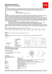
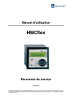
Operating instructions
MC704-H
with integrated
Powermodul PMT-3
Distribution and copying of this document, together with use and communication of its contents, are not permitted, except by express prior permission. Infringements are
actionable for damages. All rights, including rights created by patent grant or registration of a utility model or design, are reserved.
MC704-H + PMT3
Operating instructions
1. short manual
hourmeter
operating LED
(flashing during
preheat)
(bei Vorglühen)
LED alternator “D+“
LED oilpressure
LED temperature
LED auxillary
Ignition key
switch
X1
Input oilpressure switch
X2
0
X2
Input alterantor “D+“
X2
1
Output starter 50f
X3
Input temperature switch
X2
2
Output preheat
X4
Input auxillary switch
X5
Kl.31 ground battery max. 1A
X3
0
On powermodul for internal connection
X6
Output holdcoil solonoid
max. 3,5A
X3
1
On powermodul for internal connection
X3
2
On powermodul for internal connection
X7
Output signal
max. 3,5A
Kl.30 Battery +
max. 40A (2s 70A)*
max. 40A (2s 70A)*
max. 40A (2s 70A)*
X8
Output pullcoil solonoid
max. 40A (2s 70A)*
30
Ignition key switch
for internal connection
X9
Output signal for 20s in case of failure
max. 40A (2s 70A)*
15
Ignition key switch
for internal connection
X10
External Stop (NO)
50
Ignition key switch
for internal connection
X11
Input alternator “W“
75
Ignition key switch
for internal connection
*40A (2s 70A)
Is the maximum current of the diode for the reserve voltage protection of all outputs
together!
1
© ehb Irrtum vorbehalten
Y:\Vertrieb\1 - Produkte\a - Produktinformationen Vertrieb\MC 704\Bedienungsanleitung\MC704-H-PMT3_BA_EN_SP_Rev1.1.doc
MC704-H + PMT3
Bedienungsanleitung
2. List of contents
1.
short manual ..................................................................................................................... 1
2.
List of contents ................................................................................................................. 2
3.
general ............................................................................................................................... 3
4.
5.
3.1
introduction ................................................................................................................. 3
3.2
Target group ............................................................................................................... 3
3.3
Important instructions for using the device .................................................................. 4
3.4
Repairing devices ....................................................................................................... 4
Operating ........................................................................................................................... 5
4.1
Start optimisation ........................................................................................................ 5
4.2
Failure detection ......................................................................................................... 5
4.3
Prehaet ....................................................................................................................... 5
4.4
Starter protection ........................................................................................................ 5
4.5
Hourmeter ................................................................................................................... 5
4.6
Display ........................................................................................................................ 6
4.7
Ignition key switch ....................................................................................................... 6
Place into operation .......................................................................................................... 7
5.1
Inputs connection: ....................................................................................................... 7
5.2
Output connection: ...................................................................................................... 7
5.3
Assembly and connection ........................................................................................... 8
6.
Wiring diagram .................................................................................................................. 9
7.
Dokumentinformationen und Historie ........................................................................... 11
7.1
Impressum ................................................................................................................ 11
2
© ehb Irrtum vorbehalten
Y:\Vertrieb\1 - Produkte\a - Produktinformationen Vertrieb\MC 704\Bedienungsanleitung\MC704-H-PMT3_BA_EN_SP_Rev1.1.doc
MC704-H + PMT3
Operating instructions
3. general
3.1 introduction
Safety and security of your engines have the top priority in the design of our products. We want to avoid
costly repairs, downtime and the associated costs and concerns.
A high standard of quality and good value for money are part of our philosophy. Our outstanding know
how is the customized development of solutions for your specific machinery
With the ehb engine monitoring your engine get the best protection. The integrated control system offers
various possibilities for the engine control, depending on the model.
The MC 704 monitors four engine parameters, and has a addtional hour meter. The controll inputs are
programmed to stop the engine in case of a failure. An ignition key switch is integrated.
The MC 704 is a rugged designed engine monitoring, which you can use for example in construction
equipment and power generators.
3.2 Target group
This documentation is aimed at the service staff of equipment where the MC704-H-PMT3 is incorporated.
3
© ehb Irrtum vorbehalten
Y:\Vertrieb\1 - Produkte\a - Produktinformationen Vertrieb\MC 704\Bedienungsanleitung\MC704-H-PMT3_BA_EN_SP_Rev1.1.doc
MC704-H + PMT3
Bedienungsanleitung
3.3 Important instructions for using the device
Use
The device must only be operated using the accessories delivered with it.
Cleaning should only be carried out using mild cleaning agents.
Please do not introduce any objects that are not suitable for the specified purpose
into openings in the device, as this may lead to failures in the electronics.
When operating the device, comply with the general accident prevention
regulations.
Security
Do not operate the MC704-H-PMT3 within a range of strong electromagnetic fields.
Comply with the temperature ranges stated under 8.
Storage
A MC704-H-PMT3 that is not being used may only be stored in accordance with its
operating specification.
Dispatch
Whenever it is shipped, the device must always be packed in its original packaging
or in comparably robust packaging.
Improper packaging of this kind comes under the heading of Negligence, which
disqualifies the device from repair under warranty.
Maintenance
During its whole service life, the MCflex requires no maintenance and needs no
special servicing.
Opening the
MC704-h-PMT3
The MC704-H-PMT3 contains no parts that can be maintained, exchanged or
repaired by the customer or by anyone other than authorised ehb service staff.
The MC704-H-PMT3 is sealed to prevent unauthorised opening. Please note that
opening the device will damage it beyond repair.
3.4 Repairing devices
If a repair should become necessary, send the device back to:
ehb electronics GmbH
Hans-Böckler-Str. 20
30851 Langenhagen
Please ensure that a written description of the fault is included with the device. This will greatly assist the
ehb electronics gmbh Service Department in identifying the fault, so the MCflex can be more quickly
repaired and returned.
NOTE!
Ehb electronics GmbH accepts liability exclusively for the correct execution of the
work it performs and for the good quality of the materials used. Any further claims,
such as compensation for loss of profits and compensation for direct or indirect
consequential losses, such as loss of data, are excluded.
CAUTION!
Damage due to improper packaging of the device for shipping and/or unauthorised
opening of the device will invalidate the warranty!
4
© ehb Irrtum vorbehalten
Y:\Vertrieb\1 - Produkte\a - Produktinformationen Vertrieb\MC 704\Bedienungsanleitung\MC704-H-PMT3_BA_EN_SP_Rev1.1.doc
MC704-H + PMT3
4.
Operating instructions
Operating
4.1 Start optimisation
Ignition key switch position 1...all Piktograms are flashing three times (Self test).
During the preheat time the green operation LED is flashing and after more 30 seconds the ETR soleniod (Energize To Run) is aktiv and you can start the engine.
If the engine is not started during this time, the ETR solenoid is getting inactiv to protect the battery.
After starting the green LED is turn on and the status of all inputs is displayed.
You can also start the engine directly, if the ETR solenoid is turned off to protect the battery, without
turning the ignition key switch back to position „0“. The output for the ETR solenoid will turn on directly if
the ignition key switch is turned in position „2“.
4.2 Failure detection
Vor dem Start zeigen die LED’s den Zustand der Eingänge an.
Die Überwachung der Eingänge beginnt erst 7 Sekunden nach dem Start, um dem Motor die Gelegenheit
zu geben Öldruck und Ladespannung aufzubauen.
Ein Fehler an einem abstellenden Eingang (z. B. Motoröldruck) während des Betriebs, führt nach
3 Sekunden zum Abschalten des Ausgangs ETR-Betriebsmagnet und somit zum Abschalten des Motors.
Nur der Eingang der zum Abschalten des Motors geführt hat wird angezeigt. Alle anderen Anzeigen
werden unterdrückt. Somit kann einwandfrei festgestellt werden, welcher Fehler ursächlich zum
Abschalten des Motors geführt hat.
Before the start the LEDs show the status of the inputs.
The monitoring of the inputs begin until 7 seconds after the start, to give the engine the opportunity to
develop charging voltage and oil pressure.
An error on one oft he inputs during operation (for example engine oil pressure) will switch off the output
for the ETR solenoid, so that the engine will shut down. Only the led oft he input which was the reason
fort he engine shut down is turned on. So that you can easily detect the failure which was the reason oft
he engine shut down.
4.3 Prehaet
The preheat is started for a programmed time of 10 seconds, after the ignition key switch is turned in
position „1“. The operating LED is blinking during this time. If you turn the ignition key switch in position
„2“, the preheat will stop.
4.4 Starter protection
The starter protection prevent the activation oft he starter during the engine is running.
The running engine is detected with the measuring of impulses at input X11 (alternator „W“)
In this case the input 50e oft he ignition key switch is ignored and the output X21, 50f tot he starter stay
switch off.
4.5 Hourmeter
The hourmeter start counting if input X2 (alternator D+) measure voltage ( the engine is running).
5
© ehb Irrtum vorbehalten
Y:\Vertrieb\1 - Produkte\a - Produktinformationen Vertrieb\MC 704\Bedienungsanleitung\MC704-H-PMT3_BA_EN_SP_Rev1.1.doc
MC704-H + PMT3
Bedienungsanleitung
4.6 Display
1. LED green, OK-LED (Smily) during operation
Blinking during preheat
2. LED red, battery charge indicator. “D+”
3. LED red, oilpressure failure
4. LED red, temperature failure
5. LED red, auxillary failure
4.7
Ignition key switch
The ignition key switch has a mecanical starter protection.
Function of the ignition key switch
Position
meaning
0
Unit is turned off.
1
Ignition is turned on. Preheat starts, ETR solenoid is turned on.
2
Engine Start with mecanical starter protection
6
© ehb Irrtum vorbehalten
Y:\Vertrieb\1 - Produkte\a - Produktinformationen Vertrieb\MC 704\Bedienungsanleitung\MC704-H-PMT3_BA_EN_SP_Rev1.1.doc
MC704-H + PMT3
Operating instructions
5. Place into operation
Attention!
Please disconnect battery bevor
working at the electric device!
5.1 Inputs connection:
- X1
Oilpressureswitch (NC) switch against ground, shut down
- X2
alternator clamp "D+" connection "L"
GND = alternator/engine is not running, shut down
+12V = altenator/engine is running
- X3
Temperatureswitch (NO) switch against ground, shut down
- X4
auxillary switch (NO) switch against ground, shut down
- X10 External Stop (NO) switch against ground, shut down
- X11 alternator clamp "W"
Impulse = engine is running, starter protection
no impulse = engine is not running, engine can be started
- X20 clamp 30 Battery + max. 40A (2s 70A)*
- X5
clamp 31 Battery –
- X30 ignition key switch clamp 30 at Powermodul PMT-3
- X31 ignition key switch clamp at Powermodul PMT-3
- X32 ignition key switch clamp 15 at Powermodul PMT-3
5.2 Output connection:
- X6
- X8
ETR-solenoid holdcoil max. 3,5A
ETR- solenoid pullcoil max. 40A (2s 70A)*
- X7
- X9
Signal, max. 3,5A
Signal for 20s activ , max. 40A (2s 70A)*
- X22
- X21
Preheat, max. 40A (2s 70A)*
Output start 50f, max. 40A (2s 70A)*
*40A (2s 70A)
Is the maximum current of the diode for the reserve voltage protection of all outputs
together!
7
© ehb Irrtum vorbehalten
Y:\Vertrieb\1 - Produkte\a - Produktinformationen Vertrieb\MC 704\Bedienungsanleitung\MC704-H-PMT3_BA_EN_SP_Rev1.1.doc
MC704-H + PMT3
Bedienungsanleitung
5.3 Assembly and connection
Attach the device to the U-bolt in a square hole 66x66 mm, or with the threaded sockets on a flange.
Please connect the wiring harness connectors with the connectors oft he MC704-H-PMT3. The
connectors for the emergency stop are optional, connect your emergency stop if necessary
Do you need to refit a temperature switch, mount it with water-cooled engines in the water cycle (warm
side) and in the air-cooled engine cylinder head. For combined sensor / switches, connect the large
connector (6.3 mm) with the temperature instrument, the small port (4.8 mm) X3 with the temperature
switch input.
8
© ehb Irrtum vorbehalten
Y:\Vertrieb\1 - Produkte\a - Produktinformationen Vertrieb\MC 704\Bedienungsanleitung\MC704-H-PMT3_BA_EN_SP_Rev1.1.doc
MC704-H + PMT3
Operating instructions
6. Wiring diagram
9
© ehb Irrtum vorbehalten
Y:\Vertrieb\1 - Produkte\a - Produktinformationen Vertrieb\MC 704\Bedienungsanleitung\MC704-H-PMT3_BA_EN_SP_Rev1.1.doc
MC704-H + PMT3
Bedienungsanleitung
Technical Data
Parameter
condition
Voltage UB
Interference voltage - UB
6Vss, 50Hz
Voltage peaks - UB
2ms
Operating current 8-24 V UB
8-24V
Digital outputs aktiv High
X2 clamp “D+“
X6 Solenoid HC
X7 Signal
X8 Solenoid PC
X9 Signal 20s
X21 Start 50f
X22 Preheat
ignition
on/off
Critical value
min.
typ
max.
6V
12...24V
32V
14V
TA 25°C
Digital inputs aktiv High
X32 ignition key switch
clamp15
X31 ignition key switch
clamp 50
TA 25°C
Operating temperature
Storrage temperature
28V
200V
< 1mA
200mA
0,5A
3,5A
3,5A
40A
40A
40A
40A
TA 25°C
Digital inputs aktiv Low
X1 Oilpressureswitch
X2 alternotor “D+“
X3 Temperatureswitch
X4 auxillary
X10 External. Stop
(emergency stop)
X11 alternator ”W“
note
0,5A
4A*
4A*
70A*
70A*
70A*
70A*
5V
5V
5V
5V
1,5V
The operating current can
change during operation,
depend on condition oft
he outputs.
Short circuit proof
*max 2s
Low – Pegelerkennung
5Vss
Offset 2,5V
3,5V
3,5V
High – Pegelerkennung
-40°C
-55°C
+85°C
+105°C
Feuchtigkeit
(nicht kondensierend)
48h
95%
Nach SAE J1378
Humidity
6h, 10-80Hz
20g
Nach SAE J1378
Shock
72x, 9-13ms
Protection class
44g
55g
Nach SAE J1378
IP54
*40A (2s 70A)
Is the maximum current of the diode for the reserve voltage protection of all outputs
together!
10
© ehb Irrtum vorbehalten
Y:\Vertrieb\1 - Produkte\a - Produktinformationen Vertrieb\MC 704\Bedienungsanleitung\MC704-H-PMT3_BA_EN_SP_Rev1.1.doc
MC704-H + PMT3
Operating instructions
7. Dokumentinformationen und Historie
Produkt:
MC704-H mit PMT-3
Dokumentenart:
Technische Dokumentation
Version:
1.1
Erstellt am:
24.06.2008
Autor:
Klettke
ehb-electronics GmbH, Hannover
Änderungen:
Version:
Bearbeitung:
am:
von:
1.0
Erstellung
24.06.2008
Kle
1.1
Technische Daten angepasst
02.03.2010
Kle
1.2
Übersetzung englisch
22.06.2010
App
7.1 Impressum
Messen – Steuern – Regeln
Industrie Hard- und Software
Dieselmotorüberwachungen
Kundendienst:
Tel.
+49-511-123207-0
Fax.
+49-511-123207-77
eMail
[email protected]
Hans-Böckler-Str. 20
D – 30851 Langenhagen
www.ehb-electronics.de
11
© ehb Irrtum vorbehalten
Y:\Vertrieb\1 - Produkte\a - Produktinformationen Vertrieb\MC 704\Bedienungsanleitung\MC704-H-PMT3_BA_EN_SP_Rev1.1.doc