1
Operating instructions
Semi-hermetic motorcompressors
HA 5 / HG 5
8.
Electrical connection
8.1
General notes
E-0.75-03.98
Art.-No. 09963
Page 10
The electrical installation must be made according to the schematic wiring diagram
(see inside of the terminal box).
Obeserve the local protection regulations.
The maximum operating current must be the basis for dimensioning motor contactors,
supply cables, fuses (see compressor nameplate).
Compare the voltage and frequency data on the nameplate with the data of the
power supply. The motor may be connected only if there is agreement.
The motor is connected as standard for part-winding starting. The connection in the
terminal box is provided in the factory for direct starting (YY). Connect the connection
terminals according to the schematic wiring diagram in the terminal box. Delay time on
switching over max. 1 second.
8.2
Electronic protective device MP 10
(For description of function see also the enclosure in the terminal box)
The compressor motor is equipped with PTC resistor temperature sensors (motor PTC).
The measuring leads are wired with the tipping unit MP 10 which is installed
permanently in the terminal box. The unit has a reclosing lock-out. It is unlocked by
briefly interrupting the line voltage. To guarantee the locking function, the unit must be
placed as first link in the control current chain. The electrical connection must be made
exactly according to the circuit diagram (enclosure in the terminal box). If the device
trips, the overload or inadmissible operating conditions exist. Determine the cause.
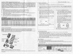
WARNING! Terminals 1 - 6 on the electronic trigger MP 10 and terminals
PTC 1 and PTC 2 on the compressor terminal board (see diagram) may not
come into contact with mains voltage. This would destroy the electronic
trigger and the PTC sensors (fig. 14).
Fig. 14