1
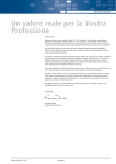
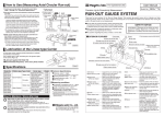
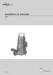
Installation and Operating Instructions
Electric Vibrators HV/VFL Series
Original Instruction
Würges Vibrationstechnik GmbH
Daimlerstraße 9
D-86356 Neusäß
Telephone +49 8 21 46 30 81
Telefax +49 8 21 46 30 84
E-Mail [email protected]
Webwww.wuerges.de
Contents
1. General Information
Page 3
2. Symbols Used
Page 4
3. Safety
• Intended use
• Skilled personnel qualifications
• General safety instructions
Page 5
4. Technical Data
• Type designation
• Nameplates
• Design and function
Page 7
5. Transport and Storage Page 10
6. Installation and Startup
• Installation
• Electrical connection
Page 11
7. Centrifugal Force Adjustment
Page 15
8. Servicing/Maintenance
Page 18
9. Spare Parts
Page 20
10. Disposal/Recycling
Page 21
2
1. General Information
The instruction manual must be read and
understood by each person in the owner‘s
company who is involved in the installation,
startup, maintenance and repair of electric
vibrators. The same applies to additional instructions for modified motors.
Würges electric vibrators are designed and
built to state-of-the-art standards and operate
safely if used as intended.
They conform to the EC Machinery Directive
2006/42/EC, the Electromagnetic Compatibility Directive 2004/108/EC and the Low-Voltage Directive 2006/95/EC.
The instruction manual must be
read carefully and in full before
using the vibrator motors.
The spare parts list of the respective motor is to be consulted for
improved understanding!
3
2. Symbols used
The following information and hazard symbols are used in these installation and operating
instructions:
ATTENTION
Important information regarding operations or procedures to which particular attention is to be paid.
EXPLOSION HAZARD
Refers to the possibility of fatal, severe or irreversible injuries caused by use of the
product in an explosive atmosphere.
HAZARD
Refers to the possibility of fatal, severe or irreversible injuries caused by live parts.
WARNING
Refers to the possibility of fatal, severe or irreversible injuries caused by general hazards.
HOT SURFACE
Refers to the possibility of severe or irreversible injuries caused by touching hot surfaces.
DISCONNECT
Refers to the fact that the motor must be
MOTOR FROM MAINS disconnected from the electricity mains and secured against being switched back on again before any work is carried out on the motor.
ENVIRONMENTALLY
Refers to the obligation to ensure environCOMPATIBLE DISPOSAL
mentally compatible disposal.
4
3. Safety
Intended use
Skilled personnel qualifications
Electric vibrators are not independently
functioning machines. They are used as the
drives of vibrating machines such as vibratory
conveyor troughs, conveyor pipes, screening
machines, grading/sorting machines and
knock-out grids.
The installation/assembly, startup and maintenance may only be carried out by authorised
and qualified skilled personnel.
These machines use vibrations to screen,
convey, remove, compact and sort or grade.
Any other use is deemed to be not as intended or misuse.
Electric vibrators are designed to generate
forces that can be destructive.
The vibrating machine must be designed for
the forces generated by the electric vibrators.
The owner is responsible for the operation of
electric vibrators.
5
General safety instructions
Electric vibrators generate vibrations. The owner of vibration machines must
protect their employees against actual or possible risks to their health and safety
caused by the effect of vibrations.
Würges Vibrationstechnik GmbH refuses to accept the responsibility for any
damage to property or personal injuries if technical changes have been made to
the product or the instructions and regulations in this instruction manual have
not been noted and followed.
Live parts can cause severe or fatal injuries.
Electric vibrators must be safely disconnected from the electricity mains before
any work is carried out on them. The required procedure is as follows:
1. Switch off vibrator motor
2. Secure against being switched back on again
3. Test for safe disconnection from the power supply
4. Allow the vibrator motor to cool
Do not touch the vibrator motors while they are running or soon after switching
them off. The surface temperature of the vibrator motors can reach such high
values during operation that there is a risk of burns.
HV/VFL series vibratory motors may not be used in hazardous areas (potentially
explosive atmospheres).
6
4. Technical Data
4.1. Type designation
Size/
Basic working moment
HV 2 / 2 - 6 B2
Housing hole pattern
Number of poles
Working moment
4.2. Nameplates
Size HV 0,1 – HV 2:
1. Type designation
2. Mains voltage
3.Speed
4. Power factor cos φ
5. Serial number
6. Thermal insulation class F (155°C)
7. Power input
8. Year built
9.Capacity
10. Mains frequency
11. Nominal current
12. Additional info
e. g. 2MV; PTC thermistor
7
Size HV 6 and larger:
1. Type designation
2. Centrifugal force
3. Mains voltage
4.Speed
5. IP protection
6.Capacity
7. Year built
8. Power factor cos φ
9. Mains frequency
10. Serial number
11. Thermal insulation class F (155°C)
12. Power input
13. Nominal current
14. Working torque
15. Additional info
e. g. 2MV; PTC thermistor
8
4.3 Design and function (using example of HV 6)
This means a rotating body, whose weight
is not distributed rotationally symmetrical or
dynamically balanced and therefore causes
vibrations. The size of these vibrations can be
controlled by weights and counterweights.
The electrical drive of the HV/VFL series is an
asynchronous motor.
The exception is the type HV 2 GL, which has
a direct current motor as a drive.
In the sizes HV 1 and HV 2 the stator is cast
under vacuum and therefore forms an assembly permanently connected to the housing.
On both shaft ends of the motor there are
eccentric unbalance plates.
1
2
3
4
Protective cover
Armature
Stator
Housing
5
6
7
8
Cable gland
Terminal box cover
Bearing end shield
Rolling bearing
9 Terminal board
10 Unbalance plates
11 Terminal box seal
9
5. Transport and Storage
Vibrator motors must always be stood on their
bases or footings!
Do not stack vibrator motors!
When they are delivered the motors must be
checked for visible transport damage!
If the motor is visibly damaged
it must not be started up. The
vibratory motor must be examined
and if necessary returned to the
manufacturer for repair.
Until they are installed the electric vibrators
should be stored in enclosed, dry rooms at a
max. ambient temperature of 40° C.
Do not lift up the motor by its
installed connection cable.
The eyebolt of the size HV 55 and larger
motors is solely intended for lifting the
vibration motor.
Note and follow the local accident prevention
regulations.
10
6. Installation and Startup
Assembly/Installation
The bolts must be secured against mechanical loosening by means of spring lock washers DIN 127 Form A, DIN 7980 or Schnorr
washers.
Electric vibrators can be installed in any
installation position. Vibrator motors may only
be built on to machines with flat, oil, grease
and paint-free and flexurally rigid mounting
surfaces.
The fixing bolts must be checked
for secure fit after approx. two
operating hours and if necessary
retightened. Other checks should
be carried out daily!
Surface quality
Improper fixing results in the
breakage of the feet of the
vibratory motor.
Only bolts in quality class 8.8 > EN ISO 4014
(DIN 931);
EN ISO 4017 (DIN 933) and nuts in quality
class 6 > 8.8 EN ISO 4032 (DIN 934) may be
used.
Minimum tightening torque
M 5
8 Nm
M 8
30 Nm
M 10
55 Nm
M 12
90 Nm
M 16
150 Nm
Vibrator foot
Mounting plate
✓ correct
✓ correct
11
incorrect
M 20
280 Nm
M 24
450 Nm
Electrical connection/cable connection
1. Switch off vibrator motor and secure against being switched back on again
2. Check for safe isolation from supply
3. Allow the motor to cool
Electric vibrators must be safely disconnected from the electricity mains
before work is carried out on them.
The required procedure is as follows:
Star connection
corresponds to higher
voltage on the nameplate
Delta connection
corresponds to lower voltage
on the nameplate
Each motor must have its own upstream
motor protection device as protection against
possible overload; the nominal current of this
protective device must be set according to
the nameplate data.
The electrical connection may only be made
by a qualified electrician or person who has
received the necessary electrical instruction in
accordance with EN-60204-1.
The mains voltage and frequency must correspond to the nameplate data. The motor must
only be connected to an electricity system that
conforms to the VDE provisions.
If two counter-rotating motors are installed, it is necessary to ensure that if one
motor fails both motors are switched off.
12
Speed control
Cable connection
The speed of our three-phase current vibrator
motors can be controlled using standard electronic frequency converters.
Only use flexible cables for the connection.
We recommend the following cable types:
HV 0,4 to HV 30: H 07 RN-F 4x1,5²
HV 30 and higher: NSSHÖU-I 4x1,5²
HV 2 GL: Ölflex 550P 2x2,5²
Please ask about the maximum allowable
final speed for each motor type!
Speed reduction is easily possible
for each type. In case of speed
increase above the value given on
the nameplate there is a risk of
accidents caused by impermissibly high centrifugal forces.
Plastic cables are unsuitable.
Attach cable lugs or crimp-type cable sockets
to the wire ends. Never solder on cable lugs
or sockets, as the wire strands near the solder
point can break under vibration.
Feed the cables into the terminal box and
connect as shown in the circuit diagram
above. (See page 14). Except HV 0.4 and HV
0.8. These are connected to a European-style
terminal strip.
When tightening the cable gland cap nut, ensure that the cable sheath is still fully covered
by the seal. If not, the cable will not be securely fixed in place, will not be strain-relieved
and will not be watertight.
13
Re-close the terminal box with seal and screw
locking device.
The power input must be checked during the
initial startup. If this is larger than the value
given on the nameplate this can be remedied
by lowering the centrifugal force.
(See Chapter 7).
The motor connection cable must be laid fixed
for approx. 0.5m after it exits from the motor.
The first fixing point of the cable and the motor
must not be able to move against each other
The cable must be checked occasionally for
during operation. The connection cable must be chafing and if necessary the cause must be
laid so that natural oscillations are avoided and removed.
there is no tensile loading of the cable.
Maximum tightening torque
terminal board nuts
M 4
1,2 Nm
14
M5
2,0 Nm
7. Centrifugal Force Setting
Crushing hazard when setting the
centrifugal force. Ensure that the
armature is fixed. Note and follow
the safety instructions on page 6!
The centrifugal force has a direct effect on
the vibration amplitude of the machine and
the power input of the motor.
To adjust the centrifugal force, dismantle both
protective covers and undo the unbalance
fixing.
If no special centrifugal force setting has been
ordered, the motor is set to maximum centrifugal force in the factory.
HV 0,4 – HV 15, HV 30/2 and HV 55/2
The centrifugal force is reduced by turning the
unbalance plates through 180° at both ends.
In the case of size HV 0.4 to HV 15, HV 30/2
and HV 55/2 motors the centrifugal force
is adjusted in steps by means of push-on
unbalance plates.
✓
✕
correct
incorrect
Maximum tightening torque of nuts at the
shaft end
The number of plates changed rotated
through 180° must be the same at both ends
of the shaft, i. e. they must be symmetrical.
(See Fig.) The unbalance plates can also be
removed for fine adjustment, they must then
be replaced by spacer discs.
HV 0,4/2
HV 1
HV 6
15
M 5
M 5
M 6
3 Nm
3 Nm
20 Nm
Centrifugal force adjustment by means of push-on unbalance plates
The centrifugal force of the motor reduces as follows if the push-on unbalance plates are
rotated through 180° or removed:
Speed 2-pole, 3000 min-1
Motor
Centrifugal force
rotated through 180° removed
HV 0,4/2
50 N
25 N
HV 0,8/2
100 N
50 N
HV 1/2
100 N
50 N
HV 2/2
220 N
110 N
HV 6/2
380 N
170 N
HV 8/2
380 N
170 N
HV 12/2
750 N
375 N
HV 15/2
750 N
375 N
HV 15/2-20
750 N
375 N
HV 15/2-25
1260 N
630 N
HV 30/2
1260 N
630 N
HV 55/2
2100 N
1050 N
Speed 4-pole, 1500 min-1
Motor
Centrifugal force
rotated through 180°
removed
HV 1/4
25 N
12,5 N
HV 2/4
55 N
27,5 N
HV 6/4
95 N
47,5 N
HV 12/4-30
187,5 N
93,75 N
HV 12/4-42
350 N
175 N
Speed 6-pole, 1000 min-1
Motor
Centrifugal force
rotated through 180°
removed
HV 6/6
42,5 N
21,25 N
HV 12/6-42
148,67N
74,34 N
Speed 8-pole, 750 min-1
Motor
Centrifugal force
rotated through 180°
removed
HV 6/8
23,75 N
11,88 N
HV 12/8-42
87,33 N
43,67 N
16
HV 30/4-75 – HV 85
From size HV 30 (except HV 30/2 and
HV 55/2) the centrifugal force is adjusted by
turning the two outer unbalance plates. The
percentage centrifugal force can be read off
from the scale on the shaft. The adjustment
made must be symmetrical.
For minimum tightening torques
of the bolts see page 11
✓
After the centrifugal force has
been adjusted the loosened bolts
and nuts must be retightened and
the protective covers must be
refitted. Otherwise there is a risk
of accidents! To ensure watertightness ensure that the seals
are intact when dismantling and
installing the protective covers.
Damaged seals must be replaced.
correct
✕
Never operate motors without
unbalance plates. This causes
damage to the bearings.
incorrect
17
8. Servicing/Maintenance
The electric vibrators must always be disconnected from the
electricity mains before any work
is carried out on it!
Lubrication
The bearings of the vibratory motors up to size
HV 65 are lubricated for life. It is not normally
necessary to carry out maintenance work on
the bearings of these motors.
1. Switch off vibrator motor
2. Secure against being switched
back on again
3. Test for safe disconnection from
the power supply
4. Allow the vibratory motor to cool
We recommend the following lubrication intervals for size HV 85 and larger:
Maintenance work to be carried out
regularly
• The surfaces of the motors must be kept free from dirt deposits in order to ensure adequate cooling.
• Check the connection cable for chafe marks and if applicable remove whatever is causing them.
• Check fixing bolts for secure fit and if necessary retighten.
• Check the seals
The fixing bolts must be retightened after approx. two operating
hours (following startup). Other
checks should be carried out
daily.
18
Motor Lubrication Grease
typeinterval quantity
in hours
in grams
HV 15/2*
1000
3
HV 30/2*
800
4
HV 55/2*
500
5
HV 85/2
300
4
HV 85/4
600
3
Supermat200
3
* For especially high loads, various motors,
some as special designs, are equipped with
lubrication nipples DIN 71412 for regreasing.
Please contact us!
Allowable operating temperature
The lubrication intervals apply to 50 Hz
operation.
In case of 60 Hz operation we recommend
halving the lubrication intervals and quantity
of grease.
The temperature on the outside of the housing
must not exceed 80°C.
This limit can be exceeded if the power input
is too high, if the speed given on the nameplate is not reached. This can cause the
winding to burn out.
We recommend the following long-life grease:
ESSO UNIREX N3.
In case of signs of bearings wear the motors
should be switched off immediately and the
special bearings replaced.
A possible cause is that the centrifugal force
is too high for the specific application or the
design is insufficiently flexurally rigid.
We recommend that you send the motors to
the manufacturer for repair (including if other
types of damage occur). This is the only way
to ensure proper repair.
One remedy is to reset the centrifugal force or
to use a motor with stronger electrical drive.
19
9. Spare Parts
We expressly point out that spare parts and
accessories that are not original parts supplied
by us have not been tested and approved by
us. Installing and/or using such products can
therefore cause negative changes to the specified design properties and therefore impair
active and/or passive safety.
To order spare parts, please refer to the spare
parts list of the respective motor.
(See: www.wuerges.de/downloads)
Please always give the following information
with each order for spare parts:
• Motor number
• Motor type
• Description, item and order number of the part
• Required quantity
Würges does not accept any liability whatsoever or provide any warranty for damage
caused by the use of non-original spare parts
and accessories.
For further information, please refer to the
exploded views given in the spare parts list.
We only provide warranty for the original spare
parts supplied by us.
20
10. Disposal and Recycling
Packaging materials and motor components
must be disposed of in an environmentally
compatible way.
PE:
Seals/gaskets
Steel:
Unbalance plates, armature and rotor, bolts,
nuts and bearing
Copper and synthetic resin:
Winding
Aluminium:
Housing, protective covers, terminal box cover
and nameplate
You can return the motors to us
for proper disposal!
They must be delivered to us
carriage paid.
21
Notes
22
Notes
23
Würges Vibrationstechnik GmbH
Daimlerstraße 9
D-86356 Neusäß
Telephone +49 8 21 46 30 81
Telefax +49 8 21 46 30 84
E-Mail [email protected]
Webwww.wuerges.de
© 4/2014
24