1
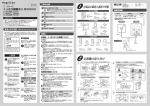
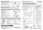
How to Use (Measuring Axial Circular Run-out)
①Install a work on the rollers. To install the work, follow
steps ① through ③ in “Eccentricity Measurement”.
②Use the front and rear work retainers to anchor the position
of a work.
This product has a structure that subtly moves works as the main
rollers are turning. To prevent a work from moving, hold it with the
front and rear work retainers.
③ Height screw for
the rear retainer
④ Position screw for
the rear retainer
Hold
⑩ Work retainer
(front)
・Loosen the position and angle screws for the front retainer.
Adjust the position of the work retainer (front) so that it holds
the front end of the work, and then tighten the screws (Figure 7).
⑨ Angle screw
for the front retainer
Figure 7
Measurement
device
Work
Right angle
Carrier type
Weight
Basic type (no carrier) 3.6kg
Slitted roller With shaft carrier
4.0kg
Linear carrier
4.3kg
Narrow Platform
Basic type (no carrier) 3.7kg
With shaft carrier
Flat roller
4.1kg
Linear carrier
4.4kg
Basic type (no carrier) 4.6kg
Slitted roller With shaft carrier
5.0kg
Linear carrier
5.3kg
Wide Platform
Basic type (no carrier) 4.7kg
With shaft carrier
Flat roller
5.1kg
Linear carrier
5.4kg
How to Maintain / Store after Use
Put the product into the supplied container case and store it in a
dry, cool, and dark place.
Avoid moisture and direct sunlight. Keep anyone other than the product’s
administrator away from the storage place.
③ Height screw for the rear retainer
SAFETY NOTICE
In this Manual,
denotes an item which can result
in expansion damage,
denotes a prohibition, and
denotes a mandatory item that must be observed.
⑪ Arm
※This illustration shows the ROG-221SS.
⑫ Top roller
⑬ Main rollers
⑭ Screw to fix the arm block
⑮ φ6 stem hole
⑯ Knob to fix measuring
devices in place
⑰ Cramp
⑱ Fine-adjuster screw
⑥ Handle
⑳ Linear-type
Carrier
⑦ Work retainer (rear)
⑧ Position screw for the front retainer
Grease nipple
Figure 9
Common Specifications
●Tolerance : Less 2 ∼ 3.5µm
※ ref : φ20mm testing workpiece (our measured value)
●Operating temperature range: 0 ∼ 40℃
●Storage temperature range:-10 ∼ 50℃
●With storage case
Measuring conditions
●Out diameter of workpiece to be φ4 ~ 30mm
(Precision roller for measurements under φ4mm optional)
●Length of workpiece to be 5 ~ 80mm
●Reference part of the workpiece must have
enough length to cramp to roller
※To prevent measurement error, tip end for workpice to be
measured on the main roller
※Softer material such as nonferrous metals(aluminum) and plastic
will cause measurement errors depending on length and outside
diameter for flexurally
Wipe away any dirt from the main rollers, the top rollers, and the
carrier. Apply them with a rustproof treatment.
The rollers and carrier are prone to rusting. Since rust on the rollers, in
particular, impacts on the overall accuracy it is important to apply them with an
adequate amount of rustproof treatment.
② Screw for the top roller
⑤ Grip
●Lubricant Applied: ISO VG32-150
●Recommended Frequency : Once every three months
Platform type Type of roller
① Arm block
Figure 8
A linear-type carrier requires periodic lubrication to maintain
smoothness of movement.
Use a grease gun to refill lubricating oil to the grease nipple
of the carrier (Figure 9).
Model No.
■EXTERIOR FEATURES
④ Position screw for the rear retainer
Probe
Lubrication of the Linear-type Carrier
Specifications
●When assigning or lending this product to a third party, make
sure that it is accompanied by this manual.
●For questions regarding this product, contact us or the seller.
※In order to hold the measuring device in place when measuring
the axial circular run-out, we recommended using a holder,
such as a magnet–base, instead of the carrier.
ROG-221S
ROG-221SS
ROG-221LS
ROG-223S
ROG-223SS
ROG-223LS
ROG-351S
ROG-351SS
ROG-351LS
ROG-353S
ROG-353SS
ROG-353LS
Thank you for your purchase of the Run-out Gauge System. This precision jig product comes with an indicator and other
measuring devices. These can be used to measure eccentricity (the run-out inside and outside of the diameter when turning the
work) or the axial circular run-out (squareness) .
●For the safety of yourself and others, please read through this
User Manual and follow its instructions carefully. Ensure that it
is retained securely in a place where it can be readily accessed.
・Loosen the position screw for the rear retainer, adjust the position
of the work retainer (rear) so that it holds the rear end of the
work, and then tighten the screw (Figure 7).
⑧ Position screw
for the front retainer
ROG-***S
RUN-OUT GAUGE SYSTEM
Hold
Work
③Make contact with the probe on the work, and then turn
the handle to conduct a measurement.
Make contact with the probe of the measuring device at a right
angle to the end surface of the work. The measuring device
measures run-out from the end of a work as it turns (Figure 8).
Model No.
Precision Jig for Eccentricity Measurement
⑦ Work retainer
(rear)
※By changing the number of washers at the bottom of the height
screw for the rear retainer you can tune the height of the work
retainer (rear). Insert one or two washers as necessary.
User Manual
For Operational Use
Niigata seiki Co., Ltd.
6-15-22, Tsukanome, Sanjo, Niigata, Japan, 955-0055
Tel. : +81-256-31-5660 Fax. : +81-256-39-7730
MAIL:[email protected]
I 203-K 1402
⑨ Angle screw for the front retainer
⑩ Work retainer (front)
①Arm block ……………… Supports the arm and the top roller.
②Screw for the top roller … Allows you to fix the vertical
position of the top roller.
③Height screw …………… Allows you to adjust the height of
the work retainer (rear) with the
for the rear retainer
number of washers.
④Position screw ………… Allows you to fix the horizontal
position of the work retainer (rear).
for the rear retainer
⑤Grip …………………… Makes it easier to rotate the handle.
However it can cause the body of
the device to shake, resulting in
measurement errors. Attach if
necessary.
⑥Handle ………………… Allows you to rotate the main roller.
⑦Work retainer (rear) …… Fixes a work to a set position when
measuring the axial circular run-out
(squareness).
⑧Position screw ………… Allows you to fix the horizontal
position of the work retainer (front).
for the front retainer
⑨Angle screw …………… Allows you to fix the angle of the
work retainer (front).
for the front retainer
⑩Work retainer (front) …… Holds a work to prevent it from
moving during the measurement of
axial circular run-out (squareness).
⑳ Carrier
⑲ Platform
⑪Arm …………………… Allows you to move the top roller
vertically to pinch a work.
⑫Top roller ……………… The upper roller that pinches the work.
⑬Main rollers …………… The lower rollers that pinch the
work. A flat-type and slit-type are
available.
⑭Screw to fix the arm block … Fixes the position of the arm block.
⑮φ6 stem hole ………… A φ6mm hole into which the stem of
the measuring device is inserted.
⑯Knob to fix measuring … Anchors the device inserted in the
φ6 stem hole.
devices in place
⑰Cramp ………………… Allows you to mount an indicator or
other measuring device.
⑱Fine-adjuster screw …… Vertically adjusts the angle of the
measuring device to allow its probe
to come in contact with a work
horizontally.
⑲Platform ………………… A base made of steel. Long-type
platforms, or platforms without a
carrier, have enough space to
mount a magnet-base. This can
then be used for measurement.
⑳Carrier ………………… A moving part that holds measuring
devices. There are three types of
carriers: shaft-type, linear-type, and
carrier-free-type.
Safety Precautions
■Items to be observed are marked by the following symbols:
Read through this User Manual and follow the instructions.
・Any use of this product in a manner that is not
described in this manual may cause an accident.
・Any use of this product for purposes not described in
this manual may cause damage, abrasion of the
product, or unexpected accidents.
Insert the work retainer (front)
into the mounting hole on the
body, and then fix it in place
with the position screw for the
front retainer.
Do not allow the work retainer
to make contact with the roller.
③Attach the top roller.
Insert the top roller into the
mounting hole on the arm.
Tighten the position screw for
the top roller to fix it in place.
⑥ Handle
⑤ Grip
②Tighten the grip to affix it
to the handle.
Use a flat-blade screwdriver to
tighten and fix the grip in place.
Tighten with a flat-blade screwdriver.
Measurement
point
⑫ Top roller
Measurement
point
Work
Work
⑬ Main rollers
⑬ Main rollers
Center line
Insert the arm block into the
groove on the body. Tighten
the screw to fix the arm block
in place.
① Arm block
Loosen the position screw for the top roller and adjust the top
roller’s position. Tighten the screw to fix it at a position where it
can make stable contact with a work (Figure 4).
Work
contact with the probe of the measuring device affixed
to the work.
Have the contact with the probe set so that the direction of
measurement is at a right angle to the work. Turn the
fine-adjuster screw to fine-adjust the angle of the measuring
device so that the probe is at a right angle (Figure 5).
⑤Attach a measurement
device.
Mount an indicator or other
measurement device.
Loosen the knob to fix a measuring
device onto the cramp and push it
towards the cramp to align the φ6
stem hole with the stem of the
measuring device. Insert the φ6
stem of the measuring device into
the hole and tighten the knob to
hold the device in place.
⑬ Main rollers
⑭ Screw to fix the arm block
② Screw for
the top roller
・Move the carrier slowly. If you move it too fast, the
measuring device or the probe might hit a work,
causing inaccuracy.
⑭ Screw to fix
the arm block
Tighten
Measurement device
Ins
ert
For devices without a carrier, use a holder such as a
magnet-base to hold the measuring device in place.
Measuring Conditions
In order to measure a work, it must first satisfy the following conditions.
Failure to comply with the conditions may damage or deform the work or
the roller.
①The work is a cylinder with an outside diameter of φ4 to 30 mm,
②The axis of the work is long enough to be pinched by
the roller, and
③The work is made of a material that is resistant to
deformation.
※Depending on its outside diameter and length, any work made
of a soft material, such as nonferrous metal (i.e. aluminum) or
plastic, is likely to bend and cause measurement errors.
⑥Undertake measurement by turning the handle.
of a work:
The carrier of this product is designed to measure run-out at
the end of a work. If you would like to measure at a different
point, refer to “Using Your Magnet-Base”, described below.
⑫ Top roller
Work
Figure 4
Turning the handle turns the main rollers, causing the work to
turn. The measuring device measures the run-out of a work
during rotation.
※Measuring eccentricity at a point other than at the end
Figure 3
Adjust the fore-and aft position
・Use the carrier to position the probe before
measurement. Note that it is impossible to move the
carrier while turning the roller.
⑯ Knob to fix measuring
devices in place
⑫ Top roller
Work
④Adjust the fore-and-aft position of the top roller.
⑤Move the carrier back and forth in order to make
④Attach the arm block.
Figure 2
Adjust the height
① Arm block
Right angle
Adjust the angle
Measurement device
Work
1
①Insert a grip into the hole
in the handle.
⑫ Top roller
Figure 1
2
Attaching the accessory grip onto the handle makes it easier to turn.
However, doing so causes a shift in the rotation support and makes it
impossible to rotate evenly. This also can causes the device body to
vibrate, resulting in measurement errors.
We recommend rotating the handle manually while keeping an even
distance from the axis of rotation. However, if you do wish to use the
grip despite its restraints, please follow the instructions below to attach
it to the handle:
Work
3
About the Grip
① Arm block
1
・The main roller, the top roller and the carrier are likely
to gather rust. It is therefore very important to rustproof
this product after use.
⑪ Arm
Tighten
Install a work between the two main rollers.
Push down on the arm to elevate the top roller. Place the work
while the roller is elevated (Figure 1).
※The nearer to the roller the measurement point is, the higher
accuracy this device produces. Adjust the work’s position so
that the measurement point is not too far from the rollers
(Figure 2).
※The slit-type rollers allow the flange (step) to be relieved. Align the work’s flange with the groove of the rollers and set it.
Loosen the screw in order to fix the position of the arm block
and adjust its height. Adjust the vertical position of the top roller
so that the point of contact between the top roller and the work
is aligned with the center line of the work. Tighten the screw to
fix the arm block back into place (Figure 3).
Insert
After using, rustproof this product and store it in
a dry place free from contact with direct sunlight.
①Install the body.
③Set up the top roller.
⑩ Work retainer (front)
2
・Doing so can cause inaccuracy or damage to the product.
・Keep in mind that if you detach any of the components,
such as the main roller, the product’s accuracy
assurance will become void.
Tighten
2
Do not disassemble or modify this product.
Inse
rt
rt
・Shocks, including those suffered from falling or loading
heavy materials, can result in inaccuracy or damage to
the product, and therefore should be avoided.
Observe the conditions required for measuring a work.
⑧ Position screw for
the front retainer
Inse
Treat this device with care.
・Ignoring any of the condition may damage or deform the roller.
⑪ Arm
②Set a work on the main rollers.
⑦ Work retainer
(rear)
1
・Use of this product in an environment other than those
described above can cause inaccuracy, damage to the
product, accidents, or injury.
(front).
Push down
Install the body of the device onto a vibration-free, flat, and
stable surface. This is necessary to achieve stable
measurement results.
1
Use this product only in environments that are:
●Dry and free from contact with water.
●Not exposed to direct sunlight.
●Stable and vibration-free.
●Flat, without any unevenness in the surface.
●Not accessible by children or individuals other than the user.
②Attach the work retainer
Washers
2
Use this product only for the precision measurement
of eccentricity or axial circular run-out.
Insert the height screw for the
rear retainer into the mounting
hole on the body, and then
tighten it. Adjust the height of
the work retainer (rear) by
changing the number
(thickness) of the washers.
2
Caution
(rear).
③ Height screw for
the rear retainer
1
Denotes a “requirement”:
You MUST do it.
①Attach the work retainer
※The main rollers and top roller are designed to deliver a high level of
accuracy. However, their construction also causes them to rust easily.
For this reason, you may not fail to wear gloves when handling them.
Tighten
sh
■The following set of indications classifies the degree of damage
that can arise from improper use of the product or a lack of
compliance with the instructions.
This mark means that ignoring the instruction
Caution can cause injury or physical damage.
Before using, assemble the components into their correct positions.
Pu
It is important to observe all of the following instructions.
In order to forestall damages to users, other persons, and property, the
instructions below must be strictly adhered to at all times in the manner
that they are described.
Denotes a “prohibition”:
You MUST NOT do it.
How to Use (Eccentricity Measurement)
Setting of the Components before Use
Main
rollers
Turn
Figure 5
⑳ Carrier
⑱ Fine-adjuster screw
How to Use (Using Your Magnet-Base)
Measurement
device
For a no-carrier-type or wide-platform-type, it is possible to mount a retainer,
such as a magnet-base, onto the base for measurement.
Right angle
●Measuring a central part of a work:
It is possible to measure at any point other than at the end of a
work. Put the probe so that it is making contact with a work at a
right angle (the direction of measurement is right angle)
(Figure 6).
●Mounting more than one measuring device to conduct
concurrent measurements of multiple points:
In addition to the supplied carrier, you can mount a
magnet-base onto the space available on the wide-platform.
This enables you to conduct concurrent measurements of
multiple points.
Magnet-Base
Work
Center line
Probe
Work
Figure 6