1
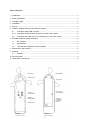
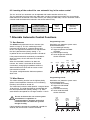
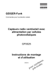
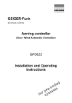
GEIGER-Funk
Sunshade controls
Automatic Radio
Controller
230V
GF0024
Installation and Operating
Instructions
d
e
d
o
c s
e m
r
p te
r
fo sys
Table of Contents
1
2
3
4
5
6
Introduction........................................................................................................................................3
Safety Instructions .............................................................................................................................3
Intended Usage...................................................................................................... ...........................3
Installation............................................................................................................. ............................4
Set-up.................................................................................................................... ............................4
GF0024, GF0025 Setting of sun and wind sensors ..........................................................................5
6.1
Learning of radio code in sensor ...........................................................................................5
6.2
Learning of the code of the sun automatic key in the motor control......................................6
7.1
Sun Sensors...........................................................................................................................6
6.1.2 Learning of sensor code of the sensor into the motor control ...............................................5
7
Alterable Automatic Control Functions................................................................... ...........................6
7.2
8
9
7.3
Wind Sensor...........................................................................................................................6
Test and Demo Operation of the Controller...........................................................................7
Maintenance and Cleaning................................................................................................................8
Disposal.............................................................................................................................................8
9.1
General...................................................................................................................................8
10 Technical Data...................................................................................................................................9
11 Declaration of Conformity..................................................................................................................9
wind wheel
LED indicator
Phillips screw
sun sensors
learning loop
for radio codes
setting of
sun threshold
setting of
wind threshold
connecting
terminals
for 230V AC
power
Phillips screw
view from below
view from above
2
1 Introduction
The purchase of an automatic radio controller GJ0024 230 V was a good decision. You have acquired a
high-quality product from the house of GEIGER.
The GJ0024 controllers make it possible to operate your sun screen systems automatically and provide
you with comfortable, individual shade that meets your wishes.
It also protects your awning or jalousies from being damaged by strong wind.
Sun and wind signals are transmitted by radio signals, thereby obviating the need for extensive laying of
cables and control wiring.
The following radio receivers with integrated motor controls can be used with the automatic radio
controller GJ0024 as a base unit:
•
•
awning controllers GFJ006
awning controllers GFJ007
The automatic radio controller GJ0024 can be correlated to receivers individually, in groups or as a
central controller.
2 Safety Instructions
•
•
•
•
•
The controller is only to be used for its intended purpose as described under Section 3 of the
operating instructions. Changes or modifications to the controller void any rights to claims under the
guarantee.
After unpacking the controller, check it right away for any damage. If it is damaged, the unit may
absolutely not be put into operation. Shipping damage is to be reported to the supplier immediately.
When it can be presumed that the controller does not operate faultlessly, it is to be immediately
taken out of service and secured against inadvertent use. This presumption exists when the case is
damaged or the unit no longer functions.
According to VDE 0022, the owner himself is responsible for compliance with EVU or VDE
regulations as well as for proper installation.
The transparent cover must be opened to make connections to supply power. Be particularly careful
that no moisture (e.g. rainwater) is able to enter the unit while it is being connected.
3 Intended Usage
•
•
The automatic radio controller GF0024 may only be used to control the operation of sun screen
systems (awnings, jalousies, roll-shutters, etc.).
GF0024 controller together with radio receivers approved for operation by the manufacturer.
3
4 Installation
The unit is suitable for surface mounting on building and roof facings.
Find a location which meets the following criteria:
•
similar wind conditions as those of the objects to be protected
•
the installation site should not be shaded by buildings, trees or bushes during the course of the day
•
•
•
similar light conditions as those prevailing at the controlled sun screen devices
the distance between the GF0024 and the nearest receiver (e.g. GFJ007) should be at least
2 metres
it must be possible to route a power cable to the unit at the location chosen (two conductors,
each with a minimum cross-sectional area of 0.75mm2)
Perform the installation as follows:
•
•
•
•
•
•
•
Use the jointed bracket to mount the GF0024 level, so that the axle of the wind wheel hangs down
vertically and the wind wheel's vanes can rotate freely. A 4 mm Allen wrench is necessary to fix the
bracket in place
Fasten the unit securely with the screws provided
Loosen the two Phillips screws and open the transparent cover. Now connect the unit's "L" and "N"
terminals to the 230V /50Hz mains (with mains power shut off!)
If the wiring must be routed upward then a loop should be formed beneath the unit so that rainwater
will drip off below the unit
Be sure that the rubber seals are firmly seated in the cable breakouts located in the bottom section
of the housing and that the top cover is also well seated in its round rubber seal
Now press the cover gently forward in the direction of the wind wheel while watching that the
housing's groove and tongue joint are completely interlocked
Screw on the housing parts with the two Phillips screws
5 Set-up
The following work must be complete before starting with the set-up procedure:
•
•
Adjust drive limit switches according to manufacturer's instructions.
Electrically connect approved GEIGER sun screen controllers according to their operating
instructions.
Check the sun screen system's directions
of rotation / travel directions!
Proceed as follows:
•
Hold the wind wheel vanes still (should not turn), set the wind potentiometer to "T" and the sun
potentiometer to "1".
4
•
•
•
Normal daylight (> 5 klx) will cause subordinate sun screen system/s to move into their shading
positions after about 6 seconds.
Now spin the wind wheel rapidly for at least 3 seconds. When the wind threshold limit has been
exceeded, the red LED on the unit will light up. The systems must be retracted immediately.
A wind lockout time of about 10 minutes will be set at radio receivers.
Conclude the procedure by setting the potentiometer to the desired limit value or the wind limit value
recommended by the textile manufacturer. For more information about this, refer to sections 7.1
"Sun sensors" and 7.2 "Wind sensor".
The automatic radio controller GF0024, 230 V, will now operate properly and reliably.
Note: Shading for your rooms will only operate automatically when the receiver function
"Sun
automat" is enabled!
6 Setting of sun and wind sensors
The device is delivered pre-coded with GEIGER coding for testing purposes.
For trouble-free operating of the system (in case of similar systems in the neighbourhood) the code has
to be changed and all following settings are required:
6.1 Learning of radio code in sensor
On delivery the GEIGER code is learned in the sensor.
Concerns only GF0025: a radio code can not be trained while in test mode (potentiometer set to T).
Hold the hand transmitter at
short range and
actuate any keys 3 sec.
Radio code
is learned
As for confirmation,
red sensor LED lights up
2 sec.
6.1.2 Learning of sensor code of the sensor into the motor control
The motor control possesses 2 memory locations for sensor code. The first code memory concerns
the sensor, the second code memory allows on and off operation of the sun automatic. The device is
delivered pre-coded with GEIGER coding. For the first learning, the GEIGER code will be replaced by a
transmitter code. If two sensor codes have already been learned and if an attempt is made to learn a
third one in addition, the last code actually stored is deleted and the new code stored instead.
Sensor
test mode setting:
wind = T sun = 0
Sensor code is
learned
Activate controller
learning mode (see
learning of radio code)
GFJ006/GFJ007
one long
signal tone
5
Spin the wind wheel
of the sensor rapidly
until red LED lights up
Setting of sensor
operating values
for wind and sun
6.2 Learning of the code of the sun automatic key in the motor control
The “on“ and “off“ sun automatic can be operated with hand transmitter with sun key.
The sun automatic keys have their own radio code. In order to activate the functions the sun automatic
radio code has to be learned in the motor control. (see setting of radio code). The sun automatic code is
a sensor code and therefore is learned in the sensor code memory.
Activate learning
mode of the motor
control (see radio
code learning)
Hold the hand
transmitter at distance
range and actuate
sun keys 1 sec.
Sensor
code
is learned
GFJ006/GFJ007
one long
signal tone
7 Alterable Automatic Control Functions
7.1 Sun Sensors
The GF0024 unit possesses two sun sensors (see
sketch on Page 2). The sun monitoring function
measures light strength in a range of about 10 to
60 klx. The brightness threshold can be adjusted with
the "Sun" potentiometer (factory setting 4 - 5).
In position '0' the sun monitoring function is turned off.
If the preset threshold is continuously exceeded for
about 5 minutes, the unit will issue the "extend"
command.
When the threshold is underrun for about 20
minutes, the "retract" command will be issued.
Programming «sun»
Should the sun protection system move
outwards/downwards:
• by increased light intensity
Higher brightness threshold:
clockwise
• by reduced light intensity
Lower brightness threshold:
counter clockwise
OFF
Continuously changing light conditions within the
aforementioned time limits will not cause a travel
command to be issued.
The optical sunlight detection field encompasses
about 180°.
Cloudy
Partly
cloudy
Twilight
7.2 Wind Sensor
Sunny
1
1
O
Bright
sky
10
O
10
Programming «wind»
Should the sun protection system move
outwards/downwards
• by increased wind velocity
Higher wind threshold:
The wind wheel measures wind speed in a range of about
clockwise
10 to 50 km/h. The wind threshold can be adjusted with
• by reduced wind velocity
the "Wind" potentiometer (factory setting 4 - 5). Each
Lower wind threshold:
scale division corresponds to a change of about 4.4 km/h.
counter clockwise
The wind monitoring function has the highest priority
(above manual operation functions or sun monitoring
functions) and cannot be turned off.
Be sure to observe the sun screen system
manufacturer's regulations or
recommendations. Changes to the wind
threshold value can reduce the system's
margin of safety.
If the threshold is continuously exceeded for a period of 3
seconds, the unit will issue a "retract" command.
Light
wind
10 km/h
(Bft 2)
6
Strong
wind
50 km/h
(Bft 7)
1
1
T
Windy
25 km/h
(Bft 4)
10
T
10
7.3 Test and Demo Operation of the Controller
The controller possesses a "Test" mode setting intended for set-up and testing. This test mode uses
shorter system times (see section 10 "Technical Data").
Test mode is active when the "Wind" potentiometer is in its "T" position. Normal mode operation is
active when the "Wind" potentiometer is again set to a value of between 1 - 10.
A new transmitter code cannot be trained while in test mode.
The test mode allows you to test the functions of the sensors with small release values.
Setting of the
sensor test mode
wind = T sun = 1
(hold on wind wheel)
Move sun
screen system
halfway
up or down
Activate sun
automatic
with hand
transmitter
Place sun sensor
into daylight (UV)
for about 6 sec.
Sun screen
system
moves
up/down
Installation is locked
T = 6 sec. in test mode and
T = 5 min. in normal operation
Black out
sun sensor
about 6 sec.
Sun screen
system
moves
up or down
Installation is locked
T = 6 sec. in test mode and
T = 20 min. in normal operation
Move sun
screen system
about halfway
up or down
Spin the wind
wheel for 3 sec.
till red LED
lights up
Sun screen
system
moves
up or down
Installation
locked
T = 10 min.
Setting of the requested
values for sun and wind
sensors
Remarks:
•
•
•
•
The sun automatic is activated when the installation stays about 90 sec. in the upper end stop
position. This function is deactivated when the upper end stop is shortly operated.
The red LED lights up only when wind comes up.
For safety reasons the installation gets locked if wind comes up and will be unlocked after a period
of 10 minutes without wind.
The installation can be unlocked if you switch off and on the power supply.
7
8 Maintenance and Cleaning
The automatic radio controller GF0024 is basically maintenance-free.
However, it is prudent to regularly check the free movement of the wind wheel, e.g. by simply observing
that it rotates even in a gentle wind.
Never use oils or greases to improve the wind wheel's freedom of motion.
Dust and insects are best removed with a clean, dry brush.
The transparent cover over the sun sensors must be kept free of contamination to ensure the unit's reliable operation with respect to sunlight.
Clean this transparent cover with a soft cloth. Moisten the cleaning cloth slightly with a mild
solution of water and hand-dishwashing liquid to remove stubborn contamination (e.g. bird
droppings).
Never use aggressive cleaning agents or chemical solutions for cleaning because these
can react with the plastic housing and may even be detrimental to the unit's functionality.
Never spray the GF0024 unit with water, e.g. from a garden hose, because it is only
protected from rainwater falling from above – not against spray water from the sides or
from below.
9 Disposal
9.1 General
Dispose of the unwanted unit according to the applicable legal regulations.
8
10 Technical Data
GF0024
Normal mode
Transmit frequency
434 MHz
Trainable code
1
Wind threshold value
10 – 50 km/h setting
Integrated wind wheel
1
Wind retract delay
3 seconds
Integrated sun sensors
2
Wind lockout time
about 180°
"Sun bright" extend command
after about 5 minutes
"Sun dark" retract command
about 10 – 60 klx
5 klx, fixed value
after about 20 minutes
after 6 seconds
Power supply
230V / 50Hz
Operating temperature
-20 to +60°C
Ingress protection class
Relative humidity
Housing dimensions (including bracket)
without / with wind wheel vanes
5 km/h, fixed value
Receiver specific, about 10 minutes
Detection angle
"Sun" setting range
Test mode
(altered values)
after 6 seconds
IP 43 (for outdoor use)
max. 95% (non-condensing)
length
260 / 295 mm
height
90 / 160 mm
width
72 / 134 mm
11 Declaration of Conformity
Gerhard Geiger GmbH & Co. • Schleifmühle 6 • D-74321 Bietigheim-Bissingen
Telephone +49 (0) 71 42 / 938-0 • Fax +49 (0) 71 42 / 938-230 • [email protected] • www.geiger.de
9
100W0609 en 0914
We herewith declare that this unit complies with the fundamental requirements and relevant regulations
set forth by Guideline 1999/5/EU and that it may be used without registration in all EU states and
Switzerland.
The declaration of conformity for this unit can be found under: www.geiger.de