1
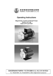
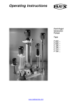
Operating Instructions Magnetically coupled Centrifugal Pumps Type RMB 3.1 – self-priming Made of PP / PVDF SONDERMANN PUMPEN + FILTER GMBH & Co. KG, D-51149 KÖLN Tel.: +49-2203-9394-0, Fax: +49-2203-9394-48, E-Mail: [email protected] Operating Instructions EG-KONFORMITÄTSERKLÄRUNG EC Declaration of Conformity Déclaration de Conformité CE Hiermit erklären wir, dass die SONDERMANN magnetisch gekuppelten Kreiselpumpen in den gelieferten Werkstoffen und Ausführungen, folgenden einschlägigen Bestimmungen entsprechen: We herewith confirm that the SONDERMANN magnetically coupled centrifugal pumps in the supplied materials and versions corresponds to the following EC-rules: Nous confirmons que les pompes centrifuges à accouplement magnétique SONDERMANN, livrées en matériaux et versions différents, sont conformes aux dispositions règlementaires suivantes: (1) EG-Richtlinie Maschinen 98/37/CE EC Machinery Directive 98/37/CE Directive CE Machines 98/37/CE (2) EG-Niederspannungsrichtlinie 2006/95/EG EC Low Voltage Directive 2006/95/EG Directive CE Bas Voltages 2006/95/EG Köln, 01.09.2007 2 Operating Instructions TABLE OF CONTENTS 1 General Information ........................................................................................... 4 1.1 Applications.................................................................................................................4 1.2 Capacity ratings ..........................................................................................................4 2 Safety .................................................................................................................. 5 3 Transportation and storage............................................................................... 7 4 5 6 7 3.1 Transportation .............................................................................................................7 3.2 Storage........................................................................................................................7 Product features and accessories .................................................................... 7 4.1 General description .....................................................................................................7 4.2 Design .........................................................................................................................7 4.3 Accessories.................................................................................................................8 Mounting and installation.................................................................................. 8 5.1 Mounting .....................................................................................................................8 5.2 Hoses and pipe lines...................................................................................................8 5.3 Electrical connection ...................................................................................................9 5.4 Check sense of rotation ............................................................................................10 Starting- and shutdown procedures............................................................... 11 6.1 Preparations for starting............................................................................................11 6.2 Starting the pump ......................................................................................................11 6.3 Operation ..................................................................................................................11 6.4 Shut-down procedure ................................................................................................12 6.5 Waste disposal..........................................................................................................12 Service and maintenance ................................................................................ 13 7.1 General information...................................................................................................13 7.2 Preventive maintenance............................................................................................13 8 Troubleshooting ............................................................................................... 14 9 Spare parts ....................................................................................................... 16 10 Appendix........................................................................................................... 20 10.1 Dimensioned drawing RMB 3.1.................................................................................20 10.2 Technical data...........................................................................................................21 10.3 Performance charts ...................................................................................................22 10.4 Labour protection and accident prevention ...............................................................23 10.5 Declaration of harmlessness .....................................................................................24 3 Operating Instructions asking for additional information, placing reorders and, in particular, ordering spare parts. For additional information, please consult your supplier or the manufacturer. 1 General Information The pump may only be used in the range of applications authorized by the manufacturer. In case of modified operating conditions, please consult your supplier and/or the manufacturer. Technical data: Voltage: 12/175 = 175 l/min. 15/225 = 225 l/min. 18/250 = 250 l/min. 12/175 = 12 m WC 15/225 = 15 m WC 18/250 = 18 m WC PP or PVDF, Ceramic, Teflon-Graphite, FKM , EPDM, FEP see type plate Motor power: 0,55 - 0,75 kW Rated current: A Speed: see type plate clockwise, seen from the pump towards the motor 2800 min-1 Protection class: IP 55 Weight approx. 11 – 13 kg Flow max.: 1.1 Fields of application Head max.: • Pumping of liquids, which are in viscosity like water, without abrasive particles • Pumping of acids and alcanlines • Pumping of gaseous fluids • Any use other that the authorized one as well as any conversion of the pump is not permitted. Materials: Sense of rotation: CAUTION! Make sure that the materials of which the pump is made, are resistant to the fluids delivered. Ask your pump’s supplier or the manufacturer for the respective chemical resistance chart. Max. temperature of the pumped liquid: PP 65°C PVDF 85°C Max. system pressure at 20°C • If you pump crystallizing fluids, make sure that the fluid does not crystallize within the pump. Should this happen, carefully clean all parts being in contact with the fluid immediately after shut off the pump. PP 2,5 bar PVDF 3,5 bar NOTE In order to determine the maximally allowed temperature of the fluid, please refer to the delivery note and/or the type plate for information on the materials used for the pump! NOTE Disassembly of the pump will cancel the right to all warranty claims! 1.2 Capacity ratings Besides the operational data of the pump, the type plate also gives its type and serial number. Please cite these data when 4 Operating Instructions The materials on the type plate are built on following key: PP = Polypropylene, glass-fiber PVDF K G V K K K = = = = = = = Warning of electricity are identified by the specific reinforced Polyvinylidenfluoride Oxide ceramic Teflon-Graphite Seal material *) Bearing: ceramic Casing thrust ring: ceramic Centering shaft: ceramic Safety sign according to DIN 4844-W Instructions non-compliance with which would give rise to malfunctioning of the machinery are identified by the word: *) possible V = FKM E = EPDM T = FEP coated CAUTION 2 Safety Signs and labels affixed to the equipment such as: This operating manual gives basic instructions which are to be observed during installation, operation and maintenance of the pump. Therefore it is imperativ that this manual has to be read by the responsible personnel/operator prior to assembly and commissioning. It is always to be kept available at the installation site. y Arrows indicating the sense of rotation y Symbols indicating fluid connections y Warnings to protect the pump from dryrunning Must be strictly observed and always kept legible. It is not only the general safety instructions contained under this main heading safety that are to be observed but also the specific information provided under the other main headings. 2.2 Qualification and training of operating personnel The personnel responsible for operation, maintenance, inspection and assembly must be adequately qualified. Scope of responsibility and supervision of the personnel must be exactly defined by the plant operator. If the staff does not have the necessary knowledge, they must be trained and instructed, which may be performed by the machine manufacturer or supplier on behalf of the plant operator. Moreover the plant operator has to make sure that the contents of the operating manual are fully understood by the personnel. 2.1 Identification of safety instructions in the operating manual Safety instructions given in this manual non-compliance with which would affect safety are identified by the following Safety sign according to DIN 4844-W9 5 Operating Instructions y Hazards resulting from electricity are to be precluded (see, for example, the VDE specifications and the bye-laws of the local power supply utilities). 2.3 Hazards in the event of noncompliance with the safety instructions Non-compliance with the safety instructions may produce a risk to the personnel as well as to the environment and the machine and results in a loss of any right to claim damages. For example non-compliance may involve the following hazards: 2.6 Safety instructions relevant for maintenance, inspection and assembly work y Endangering the environment owing to hazardous substances being released It shall be the plant operator‘s responsibility to ensure that all maintenance, inspection and assembly work is performed by authorized and qualified personnel who have adequately familiarized themselves with the subject matter by studying this manual in detail. Any work on the machine shall only be performed when it is at a standstill, it being imperative the procedure for shutting down the machine described in this manual be followed. 2.4 Compliance with regulations pertaining to safety at work Pumps and pump units which convey hazardous media must be decontaminated. y Failure of important functions of the machine/plant y Failure of specified procedures of maintenance and repair y Exposure of people to electrical, mechanical and chemical hazards When operating the pump, the safety instructions contained in this manual, the relevant national accident prevention regulations and any other service and safety instructions issued by the plant operator are to be observed! On completion of work all safety and protective facilities must be re-installed and made operative again. Prior to re-starting the machine, the instructions listed under „Initial commissioning“ have to be observed. 2.5 Safety instructions relevant for operation 2.7 Unauthorized alterations and production of spares y If hot or cold machine components involve hazards, they must be protected against accidental contact. Any modifications may be made to the machine only after consultation with the manufacturer. Using spare parts and accessories authorised by the manufacturer is in the interest of safety. Use of other parts may exempt the manufacturer from any liability. y Guards for moving parts must not be removed from the machine during operation! y Any leakage of hazardous (e.g. explosive, toxic, hot) fluids (e.g. from the shaft seal) must be drained away so as to prevent any risk occuring to persons or the environment. Statuory regulations are to be complied with. 6 Operating Instructions need to mechanically seal the shaft. So, in contrast to mechanical or gland sealed pumps, leakages through worn shaft sealing are definitely ruled out. 2.8 Unauthorized modes of operation The reliability of the machine delivered will be only guaranteed if it is used in the manner intended, in accordance with clause 1 of this manual. The limit values specified in the data sheet must under no circumstances be exceeded. 3 Transportation and storage The pump is magnetically coupled. Attention: Coming in contact with permanent magnetic parts during repair or maintenance work dangerously exposes to magnetic forces which, for example, may influence pace-makers. 3.1 Transportation The pump is delivered by the manufacturer in a ready-to-work state. In the event of damages occuring during and due to transportation the forwarding agent must make a factual statement. The pump should always be transported appropriately and according to the state of the art. , Keep your distance! The pump housing parts are sealed by static o-rings. The impeller of the pump is a radial flow wheel. Depending on the fluid to be delivered each component of the pump is available in various materials. 3.2 Storage An eventual storage place must be absolutely dry. Make sure that the interior of the pump is protected from pollutants. NOTE! 4 Product features and accessories The materials used are listed on the name plate or the delivery note! 4.1 General descritption Choice of material: The magnetically coupled pumps of group 3.1 are self-priming pumps of plastics, single-staged, horizontal in block system. Pump and electrical motor are connected by a magnet coupling which transmits the motor power to the impeller. Pump housing, rear casing, impeller, impeller magnet coating and suction tank Centering shaft Bearings Thrust rings The pumps are constructed with an integrated suction tank, which has to be filled-up prior to the first start-up! Seal material 4.2 Design Housing, impeller, impeller magnet and rear casing are made of plastics. Standard pumps are equipped with centering shafts and bearings made of oxide ceramics. The rear casing hermetically seals the fluid from the ambient atmosphere. Because of magnetic power transmission, there is no PP, PVDF Oxide ceramics Oxide ceramics Oxide ceramics Teflon-Graphite FKM, EPDM, FEP (FKM/FEP-coated) 4.3 Accessories Hose connections, thermo switches, switch-on and -off with cable and plug, 7 Operating Instructions protective motor switches, sieves, foot valves and more components are available upon inquiry. 5 Mounting and installation The place of installation should be dry and make easy to handle the pump. At moist area a good ventilation has to be guaranteed: Ambient temperature: -10 °C bis +40 °C Humidity max.: 95 % relative humidity, noncondensing The max. suction height, depending on the kind of liquid, can be reduced in reason of: NOTE! In case of higher ambient temperatures please consult your supplier/manufacturer! Friction loss in the suction line Higher temperature of liquid Higher density or/and viscosity Lower boiling point CAUTION! 5.1 Mounting Please take care for vacuum restistant connections at the suction line. If the suction line is leaky, the pump will suck-up very bad or not at all. The pump is set up to be mounted horizontally and please attend to leave enough space for maintenance. In fact of the pump is conditionally self-priming it‘s also possible to install it above the liquid level. 5.2 Hoses and pipe lines Following geodetic suction heights have to be kept: Type 12/175 15/225 18/250 Make sure that the cross-sections of the pipe lines fit the suction and discharge ports. All suction and discharge line to the pump housing should be free of tension. The weight of the hoses and pipes must not burden the housing. Max. suction height @ water 20°C 3,0 m WC 3,5 m WC 1,0 m WC CAUTION! Do not install any quick-acting stop valves into the tubes! Pressure jerks may damage the pump- and magnet housing! 5.2.1 Suction line y The suction line should be a tube or hose which will not deform by the 8 Operating Instructions resulting partial vacuum or by high temperatures. y The suction line should be as short as possible. Make sure to mount it so that there will be no gas accumulation. All electrical connections to the pump should be performed by experts only. y Especially at long suction lines and suction heights of more than 1,5 m we recommend the installation of a foot valve for shortening the suction time. The foot valve will prevent total drainage of the suction line when the pump stands still. y All electrical connections and installations of additional protection devices should be performed by experts only and in accordance with the instructions of your local power supplier and/or the Association of German Electrotechnical Engineers VDE. y When dimensioning pipelines, fittings etc., make sure to keep the flow resistances as low as possible. y The motor must be equipped with a motor circuit-breaker or a pilotherm to protect it from overloading. y Flow velocity within the fitted suction line should not exceed the limit of 1m/s. NOTE! y For easy installation and removal of the pump, a shut-off valve (but no diaphragm valve) should be built into the suction line. Motor protection devices are available with the pump's manufacturer. ACHTUNG y Make sure that the power supply has been cut off for at least 5 minutes before you start working on the terminal box of the pump. y Check out whether the power supply available corresponds to the data given on the name plate. Do not use the shut-off valve built into the suction line to adjust the delivery rate. 5.2.2 Discharge line y Standard flow velocity within the discharge line is 3m/s. y The electrical connections had to be done according to the following schematic: Three phase motor: To adjust the flow rate, we recommend installing a control element to the discharge line. 5.3 Electrical connection 9 Operating Instructions 5.4 Check sense of rotation CAUTION! Do not check the sense of rotation before the pump is filled with fluid. y Check the sense of rotation of the motor by switching it on and off in immediate succession. The sense of rotation must be in accordance with the arrow figuring on the pump. Slip a soft material, such as a paper strip, into the slits of the motor skirt to determine the sense of rotation • Mind the sense of rotation indicated by an arrow on the pump and verify if after installation. • If necessary, please change the sense of rotation by interchanging of 2 phases at the terminal board. 10 Operating Instructions y Await the procedure of sucking up until the pump has evacuated the suction line. This can last until 15 minutes. 6 Starting and shut-down procedures 6.1 Preparations for starting Always wear protective clothing! y The suction housing has to be filled-up with water respectively pump medium. Pump of PP: Open both toggle screws at the cover on the pump housing and fill-up the liquid. Set in the cover currently and tighten the toggle-screws equally. Pump of PVDF: Open the screwed cover on the pump housing and fill-up the liquid. Screw the cover and tighten it closely. Please take care the the cover at the pump housing is air-proof, otherwise the pump is not able to suck-up. y Adjust the operating point by slowly opening the shut-off valve of the discharge line. If there is no shut-off valve installed to the discharge line, the operating point is automatically adjusted in accordance with the characteristic curve of the pump. CAUTION! Avoid any dry-running of the pump! CAUTION! NOTE Do not run the pump with the discharge line closed for a longer period of time. This may result in heating up the fluid inside the pump housing and damaging interior components of the pump. We recommend installing dry-running protection devices such as flow monitors, contact manometers, differential pressure switches or level controllers. CAUTION! y Tighten all screwed connections.. Always protect the pump from coarse impurities and magnetisable metal particles within the fluid delivered. y Entirely open all valves of the suction line. 6.3 Operation If the motor-circuit breaker switched off the pump motor, proceed as follows: 6.2 Starting the pump y Switch on the motor. 11 Operating Instructions y Before switching on the motor again, check whether the impeller turns readily. CAUTION! Please comply with the respective regulations that are currently in force at your place (especially with regard to electronic scrap). y Make sure that the suction line and the pump housing are filled with fluid. y Switch on the motor. If the pump delivers for a short period of time only and then stops pumping, the magnetic coupling has been disengaged. Proceed as described in chapter 8, Troubleshooting, below. 6.4 Shut-down procedure y Switch off the motor. y Close all valves. y In case some fluid remains within the pump, secure the shut-off valves to prevent an accidental opening. y If the pump is not to be used for some time, carefully rinse it off with a clean and neutral liquid. This is to prevent remaining fluid from depositing within the pump and the sleeve bearings. y If the pump is shut down for repair or maintenance work, lock the driving unit so that it cannot be switched on. Before dismantling the pump, close the suction and the discharge lines and empty the pump under controlled conditions. y Secure all valves to prevent an accidental opening. Wear protective clothing! 6.4 Waste disposal This product as a whole as well as parts of it should be disposed of in an environmentally safe way. 12 Operating Instructions 7 Service and maintenance CAUTION! 7.1 General information When assembling or disassembling the pump, make sure that there are no magnetisable metal particles in the working area. This pump is designed for continuous operation and does not require specific maintenance. 7.2 Preventive maintenance y Although bearings, centering shaft and starting rings are designed for continuous operation, they should be periodically inspected for deposits. y If you deliver crystallising fluids, make sure that the fluid does not crystallise within the pump. Should this happen, carefully rinse off all parts being in contact with the fluid once the pump has been shut off. y Please check the condition of the static seals at regular intervals and replace them, if necessary! y Before longer shutdown periods we recommend to flush the pump cleanly. Please take care that no residual dirt can cure in the pump and will block out the impeller at the re-start. y If not only wear parts are replaced, but also repair work is to be done, this should be performed by an expert only. Inappropriate service and maintenance work often results in a waste of money. When the complete head of the pump is assembled or disassembled, magnetic forces can cause serious injury. CAUTION! After completion the pump head the impeller (item 230) and the impeller magnet (item 847.1) should be sliding along the axis of the centering shaft (item 211)! 13 Operating Instructions 8 Troubleshooting Malfunction Causes Corrective action Pump does not run when switched on No voltage Test the voltage Impurities in the pump housing Wrong sense of rotation Remove the impurities Pump housing is not filled-up Fill-up the housing with liquid Suction line is not vacuum tight Tighten the connections Discharge line is closed by valve or liquid, so that the suction line can not be evacuated Open the valve and evacuate the discharge line Resistance in the suction line is too high Specific weight and/or viscosity of the fluid is too high Reduce the suction height and/or clean the suction line Reduce the delivery rate; use a stronger magnet clutch and a more powerful motor. Pumpe does not suck-up Magnet clutch is disengaged Reverse the polarity of the motor Pump was switched off, then The rotor should have switched on again, before the stopped, before the pump can be switched on again. rotor stopped. Motor is overheating Impeller blocks out Clean the inner parts Clogged ventilator cowl Clean the ventilator and the cowl Motor is overloaded Reduce the delivery rate. Use a stronger motor. Care for a better motor cooling Pump is working, but not Gas accumulation in the lines Evacuate the lines delivering Valve in suction/delivery line Open the valves is closed Too much flow noises Cavitation Increase the suction line cross-section Motor cooling is not sufficient Reduce the delivery rate Cool down the fluid 14 Operating Instructions Malfunction Causes Corrective action Delivery rate is too low Air in the system Evacuate the system Suction and delivery line cross-sections are too small (significant losses) Increase the suction- and delivery line cross-sections Cavitation Increase the suction line corss-section Wrong sense of rotation Reverse the polarity of the motor Valve is not entirely open Pump losses are less significant than presumed Casing is damaged, damage by solid parts or dry-run Open the valves Install a flow control valve in the delivery line Dismount the pump by an expert and repair the damage Delivery rate is too high Leakage between pump and motor NOTE! At dry-running of the pump, the impeller magnet will heat-sealed with the magnet housing. The remaining liquid heats up inside the casing in fact of the rotation of the impeller on the shaft and will vaporize. The heat cannot evacuate any more, the plastic material will lose it‘s consistency and this results into a frictional welding. The pump may not run for longer time against the closed pressure line or with closed suction line. If the „dry-run“ is happened, liquid gets out of the hole in the intermediate housing between pump and motor, because by the welding of the inner parts the magnet housing can get leaky. 15 Operating Instructions 9 Spare parts 9.1 Sectional view RMB-3.1 made of PP 16 Operating Instructions 9.2 Spare parts list RMB-3.1 made of PP * Parts of wear and tear NOTE! In case of ordering spare parts, please indicate the item of the needed part, the pump type, the serial-no., motor power and drawing-no. 17 Operating Instructions 9.3 Sectional view RMB-3.1 made of PVDF 18 Operating Instructions 9.4. Spare parts list RMB-3.1 made of PVDF * Parts of wear and tear NOTE! I n case of ordering spare parts, please indicate the item of the needed part, the pump type, the serial-no., motor power and drawing-no. 19 Operating Instructions 10 Appendix 10.1 Dimensioned drawing RMB 3.1 20 Operating Instructions 10.2 Technical Data 21 Operating Instructions 10.3 Performance Charts 22 Operating Instructions 10.4 Labour protection and accident prevention NOTE! In order to protect their employees and other people as well as the environment from harmful influences and effects when handling hazardous substances, industrial and commercial companies are obliged to comply with legal provisions referring to labour protection such as the German Workplace Regulations (ArbStättV), Hazardous Substances Regulations (GefStoffV) and regulations for the prevention of accidents, as well as environmental regulations such as the German Waste Act (AbfG) and the Water Resources Law (WHG). We therefore ask you to enclose a declaration of harmlessness with any pump or component you send us for repair. With this form duly filled in and signed, you declare that the pump or the component was cleaned and thoroughly rinsed with neutral fluid before being shipped to us. Notwithstanding this, we reserve the right to refuse acceptance of repair orders for any other reason. So SONDERMANN products and their components are neither serviced nor repaired unless this declaration of harmlessness is enclosed (see page 25 below). Pumps that have been operated with radioactive substances are not accepted at all. In case that, although the pump was carefully emptied and cleaned, we have to take any safety precautions, you have to give us the necessary information when sending the pump or its component. 23 Operating Instructions 10.5 Declaration of harmlessness The undersigned herewith declares that the following pump and its accessories are harmless and asks you to service and/or repair it or them. Type of the pump: ................................................................................................................... ................................................................................................................... Serial number: ................................................... Date of delivery: ................................................... Kind of problem: ................................................................................................................... ................................................................................................................... We herewith declare that the pump was not used to deliver harmful or noxious substances; □ it was used with the following fluids: .................................................................................................................................. .................................................................................................................................. □ before being shipped, the pump was carefully emptied and cleaned inside and out; □ it is not necessary to take any special safety precautions; □ you have to take the following safety precautions with regard to residual fluids and waste disposal: ................................................................................................................................... ................................................................................................................................... Date: signature: 24 Operating Instructions 25 Operating Instructions 26 Operating Instructions 27 PUMPEN + FILTER GMBH & Co. KG August-Horch-Str.4 D - 51149 Köln (Cologne - Germany) Tel.: +49 (0) 2203/9394-0 Fax: +49 (0) 2203/9394-48 [email protected] www.sondermann-pumpen.de Subject to alterations! Copyright by SONDERMANN PUMPEN + FILTER GMBH & Co. KG • Technische Änderungen vorbehalten • SB BG3.1 08/08 D SONDERMANN