1
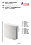
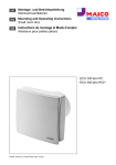
Installation and Operating Instructions No. 90 545
Fitting the ELS-VE.. ... fan unit.
This manual must be passed to the end user (tenant, propertyowner) after the
installation is completed. Section 5 is of particular importance.
RECEIPT
The box contains a fan unit and the facia.
Please check the consignment immediately on receipt for accuracy and damage. If
damaged, please notify the carrier immediately. Delay in notification may invalidate any
claims.
INSTALLATION
The ELS range is a modular system where the fan/facia is sold seperately to the casing
to allow the desired combination to be selected. The modular design allows the casing
and wiring to be undertaken as a first fix prior to plastering for example and the fan/facia
to be as a final fix.
Before starting installation ensure that you have both the casing of your choice (flush or
surface and/or fire rated) and the required fan unit.
SECTION 1
Installing the casing
Figure 1
1.1 Follow the instructions on the cardboard insert of the fan casing, ensuring that
the casing is not deformed in any way during installation (the fan must not be used
in a distorted casing as correct operation can not be guaranteed).
1.2 Make good around the casing, if necessary - the cardboard insert is designed
to prevent dirt or plaster from filling the casing during builders work.
1.3 See section 6 for electrical connection.
SECTION 2
Installing the fan and facia
(Facia & fan unit of
ELS-VE...... .)
STORAGE
The storage area must be dry, free from vibrations and variations in temperature. If this is
not the case, the fan must be protected appropriately. Damage due to storage, transportation or incorrect installation are not covered by the warranty.
APPLICATION/USE
The units (casing and fan) are designed for air extraction from toilets and bathrooms to
UK Building Regulations document F and BS 7671:2001 for zones 1, 2 and 3. If the unit
is to be used in other applications where high humidity, excesive dust, temperatures in
excess of 40 °C or long periods at standstill (not running), please contact your local Helios
dealer for advice. This also applies for special technical and electrical applications. Otherwise the units should only be used for their intended purpose.
Replacement air: The installer must ensure that there is adequate replacement air for the
fan and for any fuel burning device that may be affected by the fan.
PERFORMANCE
The unit must be installed correctly to acheive the optimum performance. This applies to
the installation of the unit, the ducting and the replacement air supply.
If installing in a room where the fan can affect a fuel burning device (e.g. a gas boiler)
which has a balanced flue, it is the installer’s responsibility to ensure that there is sufficieent replacement air to prevent fumes being drawn down the flue when the fan is operating at maximum extract rate.
Incorrect installation conditions may lead to a reduction in the system performance. Use
the largest practical size of ducting with the minimum number of bends to maintain the
minimum system resistance.
Important note
Leave the fan in its box until installation. Check that the fan is in good condition and
has not been damaged in transit. The fans are protected against water ingress to
IPX5 (suitable for zones 1, 2 & 3 to BS 7671:2001) and are double insulated.
Install the fan after all building work has finished and made good.
Installation procedure
2.1 Isolate the unit from the mains electric supply.
2.2 Check that the electric socket is correctly fitted inside the casing and that the
cable will not obstruct the fan.
2.3 Check the wiring is correct for the fan model.
2.4 Remove the fan and facia from the box. Note: hold the fan casing with both
hands.
2.5 Check that the electrical supply conforms with the electrical data on the rating
plate (voltage and frequency).
2.6 Check that the three red plugs (bayonet plugs) are in the ‘Auf’ position.
2.7 Insert the fan in the casing. The outlet of the fan must be in line with the outlet
in the casing. Push the fan carefully into the casing (see figure 2) ensuring the
red bayonet plugs are inserted into the slots in the casing.
2.8 Make sure the fan is fully home, turn all three red bayonet plugs to the ‘ZU’
position. Do not use excessive force but check that the bayonet plugs are
correctly positioned (see figures 3-4).
2.9 After fan installation press lightly against the corner where the electrical plug is
to ensure that it is fully engaged (see figure 5). Ensure the black gasket is
correctly in position.
The fan should be inspected at 6 month intervals by removing the fan from the casing
and checking that the fan impeller is clean. Also check the outlet damper i.e. clean and
operating satisfactorily.
Figure 2
Figure 3
Figure 4
Figure 5
The catalogue noise levels stated are A-rated sound power levels LWA (to DIN 45 635
part 1) The A-rated sound pressure level LA depends on the acoustic condition in the
room in which it is installed.
ACCESSORIES - USE
These units should only be used with the recommended Helios accessories otherwise
any warranty claim may be invalid. The ELS fans should not be used with a variable
speed controller (for various speeds use two or three speed models - see below).
FEATURES
Depending on the model chosen the fan will have one or more of the following features:
• Manual operation e.g via the light switch or on/off switch.
• Overrun time of approximately 5 minutes (or 12 minutes with a ZNE timer) after the fan
is manually switched off. This applies to models ELS-VEZ.. . The overrun time
depends on the fan run time. Optional delayed start of 45 seconds is available.
• Interval operation for fan model ELS-VE.. or with a ZNI timer Ref. No. 0343 (optional
accessory) for rooms not in daily use and runs fan at various intervals if fan is not used.
• Humidity controlled operation for fan model ELS-VEF.. with built in dynamic humidity
sensor, to operate when high humidity is present or when switched manually.
• PIR operation for fan model ELS-VEB .. with built in PIR (passive infra red) sensor that
operates the fan when the room is occupied and runs on for a period afterwards.
• Two and three speed operation using a Helios two (DSEL 2) or three (DSEL 3)
speed switch with suitable fans. The switches are Helios accessories.
The wiring details are given on a seperate sheet and special wiring options may be
available on request.
page 1
Installation and Operating Instructions No. 90 545
Fitting the ELS-VE.. fan unit.
All maintenance work must be carried out with the equipment fully isolated from the supply. Dismantle the unit as follows:
1. Open the facia, remove the centre bolt and facia.
2. Turn the three red bayonet plugs to the ‘Auf’ position.
3. Remove the fan by pulling the centre section and the plastic strip (in the top right
hand corner) simultaneously.
SECTION 3
Fitting the facia
3.1 Lift the two corners on the side of the Helios logo to open the facia.
3.2 Fix the facia using the short bolt (use the longer bolt only if the casing is
recessed too far for the short bolt). Do not tighten at this stage. For wall installations
position the Helios logo at the bottom.
3.3 Level the facia and tighten the centre bolt. Ensure that the facia is tight against the
wall, ceiling (see figure 5) or surface mountig box. Do not use force!
3.4 Check that the filter is correctly in position and close the facia until it snaps in
position (see figure 6 & 7).
The fan is now ready for operation.
Figure 6
Figure 7
Figure 8
Figure 9
SPECIAL INSTALLATIONS
1. Casing recessed too deep in the wall
If the casing has been fitted recessed too deep into the wall use the longer
centre bolt (enclosed in with the casing).
2. Casing protrudes out from the wall
If the casing protrudes (up to 40 mm) out of the wall and the facia does not touch the
wall, a spacer frame (accessory ELS-AR, Ref. No. 20698) can be fitted between the
facia and the wall and held in place by the facia (see figure 8).
SECTION 4
Positioning the unit - BS7671:2001
BS 7671:2001 Covering Electrical protection levels in bathrooms. Zone 0 is the
interior of the bath tub or shower basin. Also where there is no shower basin then up to
0.05 m above the floor to a vertical plane(s) radius of 1.2 m horizontally from the water
outlet at the wall where the shower head is demountable and able to be moved around
in use or to a radius 0.60 m if the shower head is not demountable. Electrical equipment inside this zone is IPX7.
Zone 1 is the area from the upper plane of zone 0 to the horizontal plane 2.25 m above
the floor and
a) by the vertical plane(s) circumscribing the bath tub or shower basin and includes the
space below the bath tub or shower basin where the space is accessable without the
use of a tool.
b) for a shower without a basin and with a demountable shower head able to be
moved around in use the vertical plane(s) at a radius of 1.2 m horizontally from the
water outlet at the wall.
c) for a shower without a basin and with a shower head which is not demountable, the
vertical plane(s) at a radius of 0.60 m from the shower head.
Electrical equipment inside this zone is IPX4.
Section 5
zon
e1
zon
e0
zon
e2
zon
e3
Bathroom zones
Service und Information
D HELIOS Ventilatoren GmbH + Co · Lupfenstraße 8 · 78056 VS-Schwenningen
CH HELIOS Ventilatoren AG · Steinackerstraße 36 · 8902 Urdorf-Zürich
A HELIOS Ventilatoren GesmbH · Siemensstraße 15 · 6023 Innsbruck
page 2
Note for the end user
The HELIOS ELS fan is easy to maintain and service. If installed vertically with the builtin filter change indicator at the bottom of the facia, a red dot will indicate when the filter
needs to be cleaned or replaced.
A dirty filter reduces the fan’s performance. A totally blocked filter will cause the fan to
overheat and cut out.
Clean the filter when the red dot appears in the facia, or every 2 months. The filter mat
may be washed many times but must be replaced when it shows signs of wear or
damage (spare filters ELF/ELSN, Ref. No. 0939). See figure 7. The clean filter indicator
does not work when the fan is installed in the ceiling and may be removed if required.
Clean the filter with warm soapy water after removing from the fan. Allow to dry before
running the fan. Do not run the fan without the filter.
SECTION 6
Electrical connection
The electrical connection to the casing can be carried out as soon as the casing is in
position. The unit has a built in terminal block/socket. Once the supply is connected to
the socket there is no need for an electrician when the fan is fitted as the power
connection is made when the fan is fully located.
The supply has to be wired into the terminal block inside the casing and conform to the
IEE regulations in BS 7671.
6.1 Remove the cardboard cover and release the terminal block/socket by depressing
the clip under it, and slide it out.
6.2 The electrical connection must be carried out by suitably qualified personnel in
accordance with the current IEE regulations. Please ensure that the electrical power
is isolated from the mains before proceeding with connection.
6.3 Insert the power cable into the casing through the cable entry point at the rear of
the casing. Cut the cable to length (225 mm = 9”) and remove about 60 mm (2.3”)
of the outer insulation. Ensure that water can not enter the casing via the supply
cable.
6.4 Release the two clips to open the terminal block/socket and wire (see figure 9) as
shown in the wiring diagram. Note each model has its own wiring diagram.
6.5 Close the terminal block/socket lid until it clicks and replace it into its original
position. Ensure that the spare cable will not block the fan unit.
6.6 An isolator with a minimum contact gap of 3 mm on all poles must be installed. It is
recommended for rooms without opening windows that the fan is wired via the light
switch with a 12 minute run on. Certain models have a bulit-in delayed start of 45
seconds and also may run on for a designed period after being turned off.
6.7 Replace the cardboard cover.
Druckschrift-Nr. 90 545 /06.03
The BS 7671: 2001 information shown here is based on extracts from the standard. For
a full copy please contact:
The Institution of Electrical Engineers P.O.Box 96, Stevenage SG1 2SD
Tel: 01438 767328
F HELIOS Ventilateurs· Z.I. La fosse à la Barbière· Rue Louis Saillant Bât. D1 93605 Aulnay sous Bois
GB HELIOS Ventilation Systems Ltd. · 5 Crown Gate · Wyncolls Road · Severalls Industrial Park ·
Colchester · Essex · CO4 9HZ Tel: 012 6 228 500
Schaltplan-Übersicht Nr. 90 749
für Ventilator-Serien ELS-VE../-VE.O..
1 N 2
VEZ 60
VEZ 100
VEI 60
3
L
N
L
N
3
3 - kleine Drehzahl
low speed
petite vitesse
2 - große Drehzahl
high speed
grande vitesse
VEZ 60/30
VEZ 100/60
1 N 2
3
SS-457
1 N
VE 60/30
VE 100/60/40
1
N
2
2
DSEL 2, 1306.002
SS-458
Zweitraum
Second room
Deuxième pièce
1
2
5
6
4
7
0
0
100
60
30
L
N
3
3
3 - kleine Drehzahl
low speed
petite vitesse
2 - große Drehzahl
high speed
grande vitesse
L
N
SS-459.2
Hauptraum
Main room
Pièce principale
VE 100/60/40
ELS
1 N 2 3
30
Dauerphase bei
Permanent life for
Alimentation permanente
pour
60 100
1
Helios Type
DSEL3
ELS VE Z/I/F Typen
L
N
SS-460
1 - kleine Drehzahl
low speed
petite vitesse
2 - große Drehzahl
high speed
grande vitesse
ZT / I, nur bei großer Stufe !
ZT / I, only for high speed !
ZT/ I, uniquement avec grande vitesse
L
N
SS-456
3
groß
1 N 2
klein
VE 60/30
SS-455
groß
SS-454
1 N 2
L
N
klein
VE 60
VE 100
SS-461
2
3
Bei Verwendung mit DSEL3
darf keine Beleuchtung mit
angeschlossen werden
When used in combination with
a DSEL 3 controller a lamp
must not be connected.
0
Pour l'utilisation du DSEL3,
aucune lampe ne peut
être raccordée.
Schaltplan-Übersicht Nr. 90 749
für Ventilator-Serien ELS-VE../-VE.O..
Vorsicht! Attention!
Externer ZNI/ZNE bei mehrtourigen VE-Ventilatoreinsätzen darf nur auf der jeweiligen höchsten Stufe angeschlossen werden. Beim Einsatz des ZNE/ZNI/ZT mit
mehreren Lüftern muß pro Lüfter ein separater ZNE/ZNI/ZT eingesetzt werden. Direkte Parallelschaltung von mehreren mehrtourigen Lüftern ist nicht erlaubt.
For multi speed ELS-VE fans an external ZNE/ZNI timer may only be connected on the highest speed. If used in combination with a number of fans, each fan needs
its own ZNE/ZNI/ZT timer. The wiring of several multi speed ELS-VE fans in parallel ist not permitted.
Pour tous types ELS-VE multi vitesses un temporisateur extérieur ZNE/ZNI ne peut être connecté que sur la grande vitesse. Il est nécessaire d’installer un temporisateur ZNE/ZNI/ZT pour chaque ventilateur utilisé. Le branchement en parallèle de plusieurs ventilateurs multi vitesses est interdit.
br - braun / brown / marron
sw - schwarz / black / noir
bl - blau / blue / bleu
ws - weiß / white / blanc
ZNI 343
ZNE 342
br
sw
3
1
2
3 4
Für Grundlüftung
Low speed
Pour ventilation
de base
VEZ 100/60
VEZ 60/30
1 N 2
1 - kleine Drehzahl
low speed
petite vitesse
2 - große Drehzahl
high speed
grande vitesse
ZT, nur bei großer Stufe!
ZT, only for high speed !
ZT, uniquement avec
grande vitesse !
SS-685
L
N
N
2
3
VEF 60
VEF 60/30
Raum Beleuchtung
room lighting
éclairage espace
1
Service und Information
D HELIOS Ventilatoren GmbH & Co · Lupfenstraße 8 · 78056 VS-Schwenningen
CH HELIOS Ventilatoren AG · Steinackerstraße 36 · 8902 Urdorf / Zürich
A HELIOS Ventilatoren · Postfach 854 · Siemensstraße 15 · 6023 Innsbruck
DSEL 2, 1306.002
1
2
5
6
4
7
0
0
L
N
92672
SS-481.2
VEB 60
3
*
1 N 2
3
*- Feuchteautomatik
deaktivieren
- Deactivate automatic
humidity control system
- Désactiver le contrôleur
d' humidité
L
N
SS-739
F
HELIOS Ventilateurs · Z.I. La Fosse à la Barbière · 2, rue Louis Saillant · 93605 Aulnay sous Bois Cedex
GB HELIOS Ventilation Systems Ltd. · 5 Crown Gate · Wyncolls Road · Severalls Industrial Park ·
Colchester · Essex · CO4 9HZ
Druckschrift-Nr. 90 749 / 03.02
L
N
SS-465
ws
ZT 1277
z.B. VE 60/30
1 N 2
bl