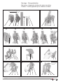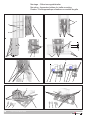
1
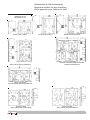
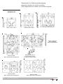
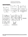
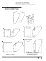
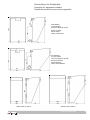
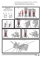
Gerätehalter und Schutzdächer für Wand-, Gitter- oder Rohrbefestigung, für 1", 1 1/4", 1 1/2" und 2" Rohre Apparatus holders and canopies for wall, trellis or pipe mounting, on 1", 1 1/4", 1 1/2" and 2" pipes Porte-appareils et capots de protection pour fixation murale, sur conduit de grille ou tube pour 1", 1 1/4", 1 1/2" et 2" tubes GHG 610 7004 P0001 D/E/F (F) Betriebsanleitung Operating instructions Mode d’emploi &=7HQWRQiYRGNSRXåLWtVLPåHWHY\åiGDW YHVYpPPDWHĜVNpPMD]\FHXSĜtVOXãQpKR ]DVWRXSHQtVSROHþQRVWL&RRSHU&URXVH +LQGV&($*YHYDãt]HPL +$NH]HOpVL~WPXWDWyWD]DGRWWRUV]iJ Q\HOYpQD&RRSHU&URXVH+LQGV&($*FpJ KHO\LNpSYLVHOHWpQLJpQ\HOKHWLPHJ '.0RQWDJHYHMOHGQLQJHQNDQRYHUV WWHVWLO DQGUH(8VSURJRJUHNYLUHUHVKRV'HUHV &RRSHU&URXVH+LQGV&($*OHYHUDQG¡U ,6HGHVLGHUDWHODWUDGX]LRQHGHOPDQXDOH RSHUDWLYRLQXQDOWUDOLQJXDGHOOD&RPXQLWj (XURSHDSRWHWHULFKLHGHUODDOYRVWUR UDSSUHVHQWDQWH&RRSHU&URXVH+LQGV&($* ((QFDVRQHFHVDULRSRGUiVROLFLWDUGHVX UHSUHVHQWDQWH&RRSHU&URXVH+LQGV&($* HVWDVLQVWUXFFLRQHVGHVHUYLFLRHQRWURLGLRPD GHOD8QLRQ(XURSHD /7âLRVQDXGRMLPRLQVWUXNFLMRVLãYHUVWRVƳ-njVǐ JLPWąMąNDOEąJDOLWHSDUHLNDODXWLDWVDNLQJRMH &RRSHU&URXVH+LQGV&($*DWVWRY\EHMHVDYR ãDO\MH (676HGDNDVXWXVMXKHQGLWRPDULLJLNHHOHV Y}LWHNVLGDRPDULLJLVDVXYDVWDVMDRPDVHVW &RRSHU&URXVH+LQGVL&($*HVLQGXVHVW /9âRHNVSOXDWƗFLMDVLQVWUXNFLMXYDOVWVYDORGƗ YDUDWSLHSUDVƯWMXVXYDOVWVDWELOGƯJDMƗ&RRSHU &URXVH+LQGV&($*SƗUVWƗYQLHFƯEƗ ),17DUYLWWDHVVDWlPlQNl\WW|RKMHHQNllQQ|V RQVDDWDYLVVDWRLVHOOD(8QNLHOHOOl7HLGlQ &RRSHU&URXVH+LQGV&($*HGXVWDMDOWDQQH 0-LVWJƫXMLWROEXGDQLOPDQZDOILOOLQJZD QD]]MRQDOLWDJƫKRPPLQJƫDQGLUUDSSUHĪHQWDQW WD &RRSHU&URXVH+LQGV&($*I SDMMLĪKRP *5ǼĮȞȤȡİȚĮıșİȚİIJĮȡĮıȘIJȦȞȠįȘȖȚȦȞȤȡȘıİ ȦȢıİĮȜȜȘȖȜȦııĮIJȘȢǼǼʌȠȡİȚȞĮȗȘIJȘșİȚĮʌȠ IJȠȞǹȞIJȚʌȡȠıȦʌȠIJȘȢ&RRSHU&URXVH +LQGV&($*³ 1/,QGLHQQRRG]DNHOLMNNDQGHYHUWDOLQJYDQ GH]HJHEUXLNVLQVWUXFWLHLQHHQDQGHUH(8WDDO ZRUGHQRSJHYUDDJGELM8Z&RRSHU&URXVH +LQGV&($*YHUWHJHQZRRUGLJLQJ COOPER Crouse-Hinds GmbH Neuer Weg - Nord 49 D 69412 Eberbach / Germany Fone +49 (0) 6271/806 - 500 Fax +49 (0) 6271/806 - 476 Internet: http://www.CEAG.de E-Mail: [email protected] 36HIRUQHFHVViULDDWUDGXomRGHVWDV LQVWUXo}HVGHRSHUDomRSDUDRXWURLGLRPDGD 8QLmR(XURSHLDSRGHVROLFLWDODMXQWRGRVHX UHSUHVHQWDQWH&RRSHU&URXVH+LQGV&($* 3/1LQLHMV]ąLQVWUXNFMrREVáXJLZRGSRZLHGQLHM ZHUVMLMĊ]\NRZHMPRĪQD]DPyZLüZ SU]HGVWDZLFLHOVWZLHILUP\&RRSHU&URXVH +LQGV&($*QDGDQ\NUDM 6(Q|YHUVlWWQLQJDYGHQQDPRQWDJHRFK VN|WVHOLQVWUXNWLRQWLOODQQDW(8VSUnNNDQYLG EHKRYEHVWlOODVIUnQ(U&RRSHU&URXVH +LQGV&($*UHSUHVHQWDQW 6.7HQWRQiYRGQDREVOXKX9iPYR9DãRP URGQRPMD]\NXSRVN\WQH]DVW~SHQLHVSRORþQRVWL &RRSHU&URXVH+LQGV&($*YR9DãHMNUDMLQH 6/21DYRGLOD]DXSRUDERY9DãHPMH]LNX ODKNR]DKWHYDWHSULSULVWRMQHP]DVWRSQLãWYX SRGMHWMD&RRSHU&URXVH+LQGV&($*Y9DãL GUåDYL Gerätehalter und Schutzdächer für Wand-, Gitterrinenoder Rohrbefestigung Apparatus holders and canopies for wall, trellis or pipe mounting Porte-appareils et capots de protection pour fixation murale, sur conduit de grille ou tube Inhalt: Contents: Contenu: 1 1.1 1.2 1.3 1.4 2 3 4 5 6 7 8 9 Inhalt ........................................ Maßbild .................................... Technische Angaben .............. Gerätehalter für Rohrbefestigung ...................... Gerätehalter für Gitterrinnenbefestigung ........... Gerätehalter für Wandbefestigung .................... Schutzdächer..................... ..... Sicherheitshinweise ................ Normenkonformität ................. Verwendungsbereich .............. Verwendung/ Eigenschaften .......................... Montage/Installation ................ Instandhaltung / Wartung ....... Reparatur / Instandsetzung/ Änderungen ............. Entsorgung / Wiederverwertung .............................. Montage: Wandgerätehalter Größe 1 - 3 .............................. Schutzdächer .......................... Rohrgerätehalter ..................... Gitterrinnengerätehalter .......... Steckbefestigung auf Gerätehalter Größe 4 und 5 ....... 2 3-7 8 Contents .................................. 2 Dimensional drawings ............. 3 - 7 1 8 1 1.1 8 1.2 8 8 8 8 8 1.3 1.4 2 3 4 5 6 7 8 9 8 8 8 Technical Data ......................... Apparatus holders for pipe mounting .................................. Apparatus holder for trellis ...... mounting .................................. Apparatus for wall mounting Canopies ................................. Safety instructions .................. Conformity with standards ..... Field of application .................. Application/ Properties ........... Mounting/Installation ............... Maintenance/Servicing ........... Repairs/Modification .............. Disposal/Recycling ................. 9 1.1 9 1.2 9 1.3 9 9 9 9 9 9 9 9 9 1.4 2 3 4 5 6 7 8 8 8 11 11 12-13 14-15 Mounting: Apparatus for wall mounting size 1 - 3 .................................. Canopies ................................. Apparatus holders for pipe mounting .................................. Apparatus holder for trellis ..... mounting ............................................... Fixing set for apparatus holders, size 4 and 5 .............. 9 11 11 12-13 14-15 16-17 16-17 Befestigung von CEAG Geräten: auf Gerätehalter Größe 1 ........ 18 CEAG apparatus for mounting: on apparatus holder size 1 ....... 8 on apparatus holder size 2 ....... 19 auf Gerätehalter Größe 2 ........ 19 Contenu ................................... Plans cotés .............................. Caractéristiques techniques ............................... Porte-appareils pour fixation sur tube ................................... Porte-appareils pour fixation sur conduit de grille ................ Porte-appareils pour fixation murale ...................................... Capots de protection .............. Consignes de sécurité ............ Conformité aux normes .......... Domaine d’utilisation ............... Utilisation/Propriétés ............... Montage/Installation ................ Maintien/Entretien ................... Réparation/Remise en état ...................................... Évacuation des déchets/ Recyclage ............................... Montage: Porte-appareils taille 1 - 3, pour fixation murale ................ Capots de protection .............. Porte-appareils pour fixation sur tube ................................... Porte-appareils pour fixation sur conduit de grille ................ Set de fixation pour porte-appareils taille 4 et 5 ..... 2 3-7 10 10 10 10 10 10 10 10 10 10 10 10 10 11 11 12-13 14-15 16-17 Appareils CEAG pour fixation: sur porte-appareils taille 1 ...... 18 on apparatus holder size 2A .... 20 auf Gerätehalter Größe 2A ...... 20 auf Gerätehalter Größe 3 (Rohr - vertikal) ........................ (Rohr - horizontal) .................... (2 x Rohr - horizontal) .............. Wand- und Gitterrinne (vertikal) ................................... (horizontal) ............................... 21 22 23 24 25 auf Gerätehalter Größe 4 (vertikal) ................................... 26 auf Gerätehalter Größe 5 (vertikal) ................................... 27 (horizontal) ............................... 28 2 Cooper Crouse-Hinds GmbH sur porte-appareils taille 2 ...... 19 on apparatus holder size 3 (pipe - vertical) ........................ (pipe - horizontal) ..................... (2 x pipe - horizontal) .............. wall and trellis (vertikal) ................................... (horizontal) ............................... 21 22 23 24 25 on apparatus holder size 4 (vertical) ................................... 26 on apparatus holder size 5 (vertical) ................................... 27 (horizontal) ............................... 28 sur porte-appareils taille 2A ... 20 sur porte-appareils taille 3 (tube - verticalement) .............. (tube - horizontalement) .......... (2 x tube - horizontalement) .... murale et conduit de grille (vertikalement) ......................... (horizontalememt).................. .. 21 22 23 24 25 sur porte-appareils taille 4 (vertikalement) ......................... 26 sur porte-appareils taille 5 (vertikalement) ......................... 27 (horizontalement) ..................... 28 Gerätehalter für Rohrbefestigung Apparatus holders for pipe mounting Porte-appareils pour fixation sur tube Maße in mm Dimensions in mm Dimensions en mm Grösse 1, Size 1, Taille 1 Grösse 3 vertikal, Size 3 vertical, Taille 3 verticalement Grösse 2, Size 2, Taille 2 Grösse 2A, Size 2A, Taille 2A 2xGrösse 3 horizontal, 2xSize 3 horizontal, 2xTaille 3 horizontalement Grösse 3 horizontal, Size 3 horizontal, Taille 3 horizontalement Grösse 4 vertikal, Size 4• vertical, Taille 4 verticalement Grösse 5 vertikal, Size 5• vertical, Taille 5 verticalement Cooper Crouse-Hinds GmbH 3 Gerätehalter für Gitterrinnenbefestigung Apparatus holders for trellis mounting Porte-appareils pour fixation sur conduit de grille Maße in mm Dimensions in mm Dimensions en mm Grösse 1, Size 1, Taille 1 Grösse 2, Size 2, Taille 2 Grösse 2A, Size 2A, Taille 2A Grösse 3, horizontal Size 3, horizontal Taille 3, horizontalement Grösse 3 vertikal, Size 3• vertical, Taille 3 verticalement Grösse 4 vertikal, Size 4• vertical, Taille 4 verticalement 4 Cooper Crouse-Hinds GmbH Rasthaken für Grösse 3, Lock-in hooks for size 3, Crochets à crans pour Taille 3 Grösse 5 vertikal, Size 5• vertical, Taille 5 verticalement Gerätehalter für Wandbefestigung Apparatus holders for wall mounting Porte-appareils pour fixation murale Maße in mm, X = Befestigungsmaße Dimensions in mm, X = fixing dimensions Dimensions en mm, X = dim. de fixation Grösse 1, Size 1, Taille 1 Grösse 2, Size 2, Taille 2 Grösse 2A, Size 2A, Taille 2A Grösse 3, horizontal Size 3, horizontal Taille 3, horizontalement Grösse 3 vertikal, Size 3• vertical, Taille 3 verticalement Befestigungshaken für Grösse 3, Fixing hooks for size 3, Crochets de serrage pour Taille 3 Cooper Crouse-Hinds GmbH 5 Schutzdächer für Gerätehalter Canopies for apparatus holders Capots de protection pour porte-appareils Maße in mm ohne Kantenschutz Dimensions in mm without protective edging Dimensions en mm sans bordure de protection Grösse 1, Size 1, Taille 1 Grösse 2A, Size 2A, •Taille 2A 6 Cooper Crouse-Hinds GmbH Grösse 2, Size 2, Taille 2 für Gitterrinnenhalter, for trellis holders, pour porte-appareils conduit de grille Grösse 3 vertikal, Size 3• vertical, Taille 3 verticalement Schutzdächer für Gerätehalter Canopies for apparatus holders Capots de protection pour porte-appareils für Rohrhalter, for pipe holders, pour porte-appareils de tube Grösse 3 vertikal, Size 3• vertical, Taille 3 verticalement für Rohrhalter, for pipe holders, pour porte-appareils de tube Grösse 3 horizontal, Size 3• horizontal, Taille 3 horizontalement Grösse 4, Size 4,• Taille 4 Grösse 5, Size 5,• Taille 5 Cooper Crouse-Hinds GmbH 7 Gerätehalter und Schutzdächer für Wand-, Gitterrinenoder Rohrbefestigung 1 Technische Daten 1.1 Gerätehalter Rohrdurchmesser 1" 1 1/4 " 1 1/2 " 2" Vierkantprofil für Rohrbefestigung Klemmbereich 27 - 30 mm 2) 40 - 43 mm 1) 47 - 50 mm 1) 59 - 62 mm 1) 40 x 40 mm 1) Adapterstücke sind im Lieferumfang der Gerätehalter enthalten. 2) Adapterstück ist optional unter der Bestellnummer GHG 610 1953 R0020 nachbestellbar (1VE=10 Stück). Die Verwendung von anderen Abmessungen und Profilen ist mit COOPER Crouse-Hinds GmbH abzustimmen. Zulässige Belastung pro Gerätehalter Größe 1 , 2 und 2A max. 50 kg Größe 3 vertikal max. 75 kg Größe 3 horizontal max. 50 kg Größe 3 (2 x) max. 75 kg Größe 4 max. 50 kg Größe 5 max. 50 kg Gewicht pro Gerätehalter Größe 1 ca. 392 g Größe 2 ca. 457 g Größe 2A ca. 503 g Größe 3 ca. 1.060 g Größe 4 ca. 620 g Größe 5 ca. 780 g 1.2 Gerätehalter für Gitterbefestigung Für Gitterstabdurchmesser 4,5 - 5 mm Zulässige Belastung pro Gerätehalter pro Gerätehalter im Eingriff: 2 Rasthaken 4 Rasthaken Größe 1 max. 25 kg max. 50 kg Größe 2 max. 25 kg max. 50 kg Größe 2A max. 25 kg max. 50 kg Größe 3 max. 25 kg max. 50 kg Größe 4 max. 25 kg max. 50 kg Größe 5 max. 25 kg max. 50 kg Gewicht pro Gerätehalter Größe 1 ca. 111 g Größe 2 ca. 151 g Größe 2A ca. 196 g Größe 3 ca. 330 g Größe 4 ca. 255 g Größe 5 ca. 410 g 1.3 Gerätehalter für Wandbefestigung Zulässige Belastung pro Gerätehalter Befestigungen pro Gerätehalter: 2 Schrauben 4 Schrauben Größe 1 max. 25 kg Größe 2 max. 25 kg max. 50 kg Größe 2A max. 25 kg max. 50 kg Größe 3 max. 25 kg max. 50 kg Gewicht pro Gerätehalter Größe 1 ca. 100 g Größe 2 ca. 135 g Größe 2A ca. 180 g Größe 3 ca. 330 g Größe 4 ca. 235 g Größe 5 ca. 390 g 8 Cooper Crouse-Hinds GmbH 1.4 Schutzdächer Gewicht pro Schutzdach Größe 1 Größe 2 Größe 2A Größe 3 (Gitter-vertik.) Größe 3 (Gitter-horiz.) Größe 3 (Rohr- vertik). Größe 4 Größe 5 2 ca. 410 g ca. 482 g ca. 620 g ca. 925 g ca. 1.195 g ca. 859 g ca. 552 g ca. 853 g Sicherheitshinweise Die Schutzdächer sind auf den zugehörigen Gerätehaltern zu befestigen.Sie sind mit einem Kantenschutz versehen. Achtung: Der Kantenschutz darf wegen der Unfallgefahr nicht von den Schutzdächern entfernt werden! Die Verantwortung hinsichtlich bestimmungsgemäßer Verwendung dieser Gerätehalter und Schutzdächer liegt allein beim Betreiber. Lesen Sie vor Montagebeginn der Gerätehalter und der Schutzdächer diese Montageanleitung und die Betriebsanleitung des zu montierenden Gerätes sorgfältig durch. 6 Es ist darauf zu achten, dass die Gerätehalter und Schutzdächer nur in einwandfreiem Zustand gemäß der Montageanleitung montiert werden. Unsachgemäße Montage der Gerätehalter und Schutzdächer kann zum Verlust der Garantie führen. Die Gerätehalter und Schutzdächer sind entsprechend der Montagebilder Seite 11-17 zu montieren. 7 3 Normenkonformität Die Gerätehalter und Schutzdächer wurden entsprechend dem Stand der Technik und gemäß DIN EN ISO 9001 entwickelt, gefertigt und geprüft. 4 Verwendungsbereich Die Gerätehalter sind zum Befestigen von Schaltgeräten in Industrieanlagen jeglicher Art geeignet. Die eingesetzten Materialien einschließlich der außenliegenden Metallteile bestehen aus hochwertigen Werkstoffen, die einen anwendungsgerechten Korrosionsschutz und Chemikalienresistenz in "normaler Industrieatmosphäre" gewährleisten: - hochfestes Polyamid - Edelstahl AISI 304. Bei Einsatz in extrem aggressiver Atmosphäre sind die zusätzlichen Informationen über die Chemikalienbeständigkeit der eingesetzten Kunststoffe dem Datenblatt GHG 902 4001 P0001 zu entnehmen. 5 Verwendung / Eigenschaften Die Gerätehalter dienen nur zur Schnell- und Schraubbefestigung von explosionsgeschützten Schaltgeräten, Abzweigdosen, Klemmenkästen, Steuergeräten und Verteilungen der COOPER Crouse-Hinds GmbH. Andere Betriebsmittel und Geräte können im Rahmen der zulässigen Belastung (siehe technische Daten) mit geeigneten Schrauben befestigt werden. Montage / Installation Instandhaltung / Wartung Die erforderlichen Wartungsintervalle sind anwendungsspezifisch und daher in Abhängigkeit von den Einsatzbedingungen vom Betreiber festzulegen. Sollte bei einer Wartung festgestellt werden, daß Instandsetzungsarbeiten erforderlich sind, ist Abschnitt 8 dieser Betriebsanleitung zu beachten. 8 Reparatur / Änderungen Reparaturen dürfen nur unter Verwendung von CEAG Originalersatzteilen vorgenommen werden. Umbauten oder Änderungen an den Gerätehaltern sind nicht gestattet; ausgenommen ist das Bohren von Befestigungslöchern zur Gerätebefestigung. 9 Entsorgung / Wiederverwertung Bei der Entsorgung der Gerätehalter sind die jeweils geltenden nationalen Abfallbeseitigungs-vorschriften zu beachten. Zur Erleichterung der Wiederverwertbarkeit von Einzelteilen sind Kunststoffteile mit dem Kennzeichen des verwendeten Kunststoffes versehen. Produktänderungen und -ergänzungen sind vorbehalten. Apparatus holders and canopies for wall, trellis or pipe mounting 1 Technical data 1.1 Apparatus holders for pipe mounting Pipe diameter Clamping range 1" 27 - 30 mm 2) 1 1/4 " 40 - 43 mm 1) 1 1/2 " 47 - 50 mm 1) 2" 59 - 62 mm 1) Square profile 40 x 40 mm 1) Adapters included in scope of delivery of apparatus holders 2) Adapter is optional and can be ordered under the Order No. GHG 610 1953 R0020, can be ordered separately (packed in units of 10). The use of other dimensions and profiles to be approved by COOPER Crouse-Hinds. Permissible load per holder Size 1 , 2 and 2A Size 3 vertical Size 3 horizontal Size 3 (2 x) Size 4 SizeSize 5 Weight per apparatus holder Size 1 Size 2 Size 2A Size 3 Size 4 Size 5 max. 50 kg max. 75 kg max. 50 kg max. 75 kg max. 50 kg max. 50 kg ca. 392 g ca. 457 g ca. 503 g ca. 1.060 g ca. 620 g ca. 780 g 1.2 Apparatus holders for trellis mounting For bar diameters 4.5 – 5 mm Permissible load per apparatus holder Number of hooks engaged per apparatus holder: 2 hooks 4 hooks Size 1 max. 25 kg max. 50 kg Size 2 max. 25 kg max. 50 kg Size 2A max. 25 kg max. 50 kg Size 3 max. 25 kg max. 50 kg Size 4 max. 25 kg max. 50 kg Size 5 max. 25 kg max. 50 kg Weight per apparatus holder Size 1 ca. 111 g Size 2 ca. 151 g Size 2A ca. 196 g Size 3 ca. 330 g Size 4 ca. 255 g Size 5 ca. 410 g 1.3 Apparatus holders for wall mounting Permissible load per apparatus holder Fixings per apparatus holder: 2 screws 4 screws Size 1 max. 25 kg Size 2 max. 25 kg max. 50 kg Size 2A max. 25 kg max. 50 kg Size 3 max. 25 kg max. 50 kg Weight per apparatus holder Size 1 ca. 100 g Size 2 ca. 135 g Size 2A ca. 180 g Size 3 ca. 330 g Size 4 ca. 235 g Size 5 ca. 390 g 1.4 Canopies Weight per canopy Size 1 Size 2 Size 2A Size 3 (vertical trellis bars) Size 3 (horizontal trellis bars) Size 3 (pipe - vertical) Size 4 Size 5 2 ca. 410 g ca. 482 g ca. 620 g ca. 925 g ca. 1.195 g ca. 859 g ca. 552 g ca. 853 g The canopies are to be mounted onto the associated apparatus holders and shall be fitted with a protective edging. Warning: Do not remove the protective edging from the canopy - injury hazard ! The sole responsibility with respect to the suitability and proper use of the these apparatus holders and canopies lies with the operator. Safety instructions Before mounting apparatus holders and canopies, read these mounting instructions and the operating instructions of the apparatus to be mounted through carefully. Ensure that the apparatus holders and the canopies are in perfect condition and that they are mounted in accordance with the mounting instructions. 6 The apparatus holders and canopies are to be mounted acc. to the photos shown on page 11 - 17. The inappropriate mounting of the apparatus holders and canopies, can entail the loss of warrenty. 7 3 Conformity with standards The apparatus holders and canopies were designed, manufactured and tested according to the state of the art and to DIN EN ISO 9001. 4 Field of application The apparatus holders are suited for mounting switchgear in industrial plants of all types. The materials used, including the exterior metal parts, are high quality materials that ensure a corrosion resistance and resistance to chemical substances according to the requirements for use in a ”normal industrial atmosphere”: - highly resistant polyamide - stainless steel AISI 304. If they are intended for use in particularly aggressive atmospheres, additional information on the chemical stability of the plastics used can be found in the data sheet GHG 902 4001 P0001. 5 Application / Properties The apparatus holders are only intended for the snap-on and screw mounting of explosion-protected switchgear, junction boxes, terminal boxes, control stations and distributions from Messrs. COOPER CrouseHinds GmbH. Mounting / Installation Maintenance/Servicing The necessary intervals between servicing depend upon the specific application and shall be stipulated by the operator according to the respective operating conditions. If, in the course of servicing, it is ascertained, that repairs are necessary, section 8 of these mounting instructions shall be observed. 8 Repairs /Modifications Only original CEAG parts shall be used for carrying out repairs. With the exception of the drilling of fixing holes for fixing apparatus, the conversion or modification of apparatus holders is not permitted. 9 Disposal / Recycling The respective valid national regulations for waste disposal shall be observed when disposing of apparatus holders. To facilitate the recycling of individual parts, plastic parts are marked with the symbol of the of the plastic used. The product range is subject to changes and additions. Other apparatus can be mounted with suitable screws within the scope of the permissible load (see Technical data). Cooper Crouse-Hinds GmbH 9 Porte-appareils et capots de protection pour fixation murale, sur conduit de grille ou tube 1 Caractéristiques techniques 1.1 Porte-appareils pour fixation sur tube Diamètre du tube Diamètre extérieur du tube / de fixation 1" 27 - 30 mm 2) 1 1/4 " 40 - 43 mm 1) 1 1/2 " 47 - 50 mm 1) 2" 59 - 62 mm 1) Tube carré 40 x 40 mm 1) les adaptateurs sont fournis avec le porte-appareil. 2) l’adaptateur est en proposé en option. Ref. commande GHG610 1953 R0020 (pack de 10 pièces). La fixation sur des diamètres et dimensions de profilés autres est soumise à l’approbation de la société COOPER Crouse-Hinds GmbH. 1.2 Capots de protection Poids par capot de protection Taille 1 env. 410 g Taille 2 env. 482 g Taille 2A env. 620 g Taille 3 (poteau vertic. en grillage) env. 925 g Taille 3 (poteau horiz. en grillage) env. 1.195 g Taille 3 (tube vertical) env. 859 g Taille 4 env. 552 g Taille 5 env. 853 g Les capots de protection doivent être fixés sur les porte-appareils. Ces capots sont munis d’une protection pour leurs arêtes. 2 6 Lisez ces instructions de montage ainsi que le mode d’emploi des appareils à installer avant de commencer le montage de ces porte-appareils et capots de protection. Charge admissible par porte-appareil Taille 1 , 2 et 2A max. 50 kg Taille 3 vertical max. 75 kg Taille 3 horizontal max. 50 kg Taille 3 (2 x) max. 75 kg Taille 4 max. 50 kg Taille 5 max. 50 kg Poids par porte-appareil Taille 1 env. 392 g Taille 2 env. 457 g Taille 2A env. 503 g Taille 3 env. 1.060 g Taille 4 env. 620 g Taille 5 env. 780 g 3 1.2 4 Porte-appareils pour fixation sur conduit de grille Pour poteau en grillage de diamètre 4,5 – 5 mm Charge admissible par porte-appareil et selon le nombre de points de contact: 2 crochets à crans 4 crochets à crans Taille 1 max. 25 kg max. 50 kg Taille 2 max. 25 kg max. 50 kg Taille 2A max. 25 kg max. 50 kg Taille 3 max. 25 kg max. 50 kg Taille 4 max. 25 kg max. 50 kg Taille 5 max. 25 kg max. 50 kg Poids par porte-appareil Taille 1 env. 111 g Taille 2 env. 151 g Taille 2A env. 196 g Taille 3 env. 330 g Taille 4 env. 255 g Taille 5 env. 410 g 1.3 Porte-appareils pour fixation murale Charge admissible par porte-appareil et selon le nombre de vis de fixation : 2 vis 4 vis Taille 1 max. 25 kg Taille 2 max. 25 kg max. 50 kg Taille 2A max. 25 kg max. 50 kg Taille 3 max. 25 kg max. 50 kg Poids par porte-appareil Taille 1 env. 100 g Taille 2 env. 135 g Taille 2A env. 180 g Taille 3 env. 330 g Taille 4 env. 235 g Taille 5 env. 390 g 10 Cooper Crouse-Hinds GmbH Consignes de sécurité On veillera à ce que les porte-appareils et capots de protection soient en parfait état, conformément aux instructions de montage. Conformité aux normes Les porte-appareils et capots de protection ont été développés, fabriqués et testés en l’état de la technique et selon la norme DIN EN ISO 9001. Domaine d’utilisation Ces porte-appareils sont prévus pour la fixation d’appareils de commutation montés dans des installations industrielles de toutes sortes. Les matières plastiques employées ainsi que les parties métalliques sont de qualité supérieure et assurent une protection contre la corrosion et une résistance aux agents chimiques appropriée en ”atmosphère industrielle normale”: Polyamide particulièrement résistant Acier inoxydable AISI 304 En cas d’utilisation en atmosphère particulièrement agressive, on tiendra compte des informations supplémentaires relatives à la résistance aux agents chimiques des matières plastiques employées. Voir fiche technique GHG 902 4001 P0001. 5 Utilisation / Propriétés Les porte-appareils servent uniquement à fixer rapidement par vissage des appareils de commutation, boites de jonction, boites de bornes, postes de commande et tableaux de distribution de la gamme de produits COOPER Crouse-Hinds GmbH. Des appareils autres peuvent être également fixés avec des vis appropriées et en respect des charges admissibles (voir caractéristiques techniques). Attention: cette protection des arêtes ne doit être en aucun cas retirée pour des raisons de sécurité. La responsabilité relative à l’utilisation conforme de ces porte-appareils et capots de protection est celle de l’utilisateur seul. Montage / Installation Ces porte-appareils et capots de protection doivent être montés conformément aux schémas de montage des pages 11 à 17. Un montage non conforme des porteappareils et capots de protection peut entraîner la perte de la garantie. 7 Maintien / Entretien Les intervalles d’entretien obligatoires sont à déterminer par l’utilisateur en fonction de l’emploi spécifique et des conditions d’utilisation de ces produits. Si à l’occasion de travaux d’entretien, une remise en état était jugée nécessaire, les directives du chapitre 8 de cette notice devraient être respectées. 8 Réparations / Remise en état Les travaux de remise en état / réparation qui concernent la protection contre le risque d’explosion ne doivent être effectués qu’en utilisant des pièces originales de CEAG. Toute transformation ou modification de ces éléments est interdite. La seule exception est le perçage de pas de fixation pour le montage d’appareils. 9 Evacuation des déchets / Recyclage Lors de l’évacuation de ces éléments, la réglementation nationale en vigueur devra être respectée. Afin de faciliter le recyclage de ces éléments, les parties en plastique sont marquées du signe distinctif de la matière plastique employée. Sous réserve de modification ou d’informations complémentaires. Wandgerätehalter und Schutzdach Apparatus holders for wall mounting and canopy Porte-appareils pour fixation murale et capots de protection 1 2 2 Der Gerätehalter für Wandmontage ist in f olgender Reihenfolge zu montieren: Mount the apparatus holder for wall mounting as follows: Le porte-appareils pour fixation murale doit se monter comme suit : Pos 1 1 x Gerätehalter Pos 2 4 x Befestigungslöcher Item 1 Item 2 Pos. 1 1 x porte-appareils Pos. 2 4 x pas de fixation 2 / 4 x Zylinderkopfschraube M5/M6 2 / 4 x Sechskantschraube M6 2 / 4 x Sechskantmutter M6 Der Gerätehalter für Wandbefestigung, Pos. 1, kann wahlweise mit Zylinderkopfschrauben oder Sechskantschrauben bzw. Sechskantmuttern an ebenen Flächen angeschraubt werden. Dabei ist darauf zu achten, dass die Schraubenköpfe bzw. die Muttern nicht über die Frontseite des Gerätehalters hinausragen. Sonst kann das zu montierende Gerät nicht mehr befestigt werden. 1 x apparatus holder 4 x fixing holes 2/ 4 x vis à tête cylindrique M5/M6 2/ 4 x vis hexagonale M6 2/ 4 x écrou hexagonal M6 2 / 4 x cylinder head screw M5/M6 2 / 4 x hexagonal head screw M6 2 / 4 x hexagonal nut M6 The apparatus holder for wall mounting, Item 1, can be screwed onto an even surface using cylinder or hexagonal head screws or hexagonal nuts. Le porte-appareils pour fixation murale (Pos. 1) peut être fixé au choix avec des vis à tête cylindrique ou des vis hexagonales (et écrous hexagonaux) sur des surfaces planes. It is necessary to ensure that the heads of the screws or the nuts do not jut out beyond the front of the apparatus holder. Ce faisant, on veillera à ce que les têtes des vis et des écrous ne dépassent pas de la face frontale du porte-appareils. Otherwise the apparatus to be mounted cannot be fixed in position. Si c’était le cas, l’appareil devant être monté ne pourrait être fixé. 1 3 2 4 Die Schutzdächer sind in folgender Reihenfolge auf die Gerätehalter zu montieren: Mount the canopies onto the apparatus holders as follows: Le capot de protection doit être monté comme suit sur le porte-appareils : Pos. 1 Pos. 2 Pos. 3 Pos. 4 Item 1 Item 2 Item 3 Item 4 Pos. 1 Pos. 2 Pos. 3 Pos. 4 Schutzdach Gerätehalter Befestigungshaken Befestigungslaschen Das Schutzdach, Pos. 1, ist mit seinen Befestigungshaken, Pos. 3, auf die Befestigungslaschen, Pos. 4, des Gerätehalters, Pos. 2, aufzustecken. Dabei ist darauf zu achten, dass die Befestigungshaken alle in die Befestigungslaschen des Gerätehalters eingreifen. Danach wird das Schutzdach bis zum Anschlag nach unten auf den Gerätehalter geschoben. Canopy Apparatus holder Fixing hooks Fixing lugs capot de protection porte-appareils crochets de fixation pattes de fixation Clip the canopy, Item 1, onto the fixing lugs, Item 4, of the apparatus holder, Item 2, with the hooks, Item 3. Le capot de protection (Pos. 1) doit être enclipsé sur les pattes de fixation (Pos. 4) au moyen de ses crochets de fixation (Pos. 3). Ensure that the fixing hooks engage in all the fixing lugs of the apparatus holder. Ce faisant, on veillera à ce que tous les crochets de fixation sont bien insérés dans les pattes du porte-appareils. Then push the canopy downwards onto the apparatus holder until it reaches the stop. Ensuite, on encastrera le capot de protection par l’arrière et jusqu’à la butée sur le porteappareils. Cooper Crouse-Hinds GmbH 11 Montage - Rohrgerätehalter Mounting - Apparatus holders for pipe mounting Fixation - Porte-appareils pour fixation au tubes 1 3 10 11 9 13 2 2A 1 12 1 4 2B 2 3 5 2C 3 4 4 1 6 1 2D 2E 3/4 1 5 4 2 3 5 6 7 3/4/5/6 12 13 11 2F 1 9/10 1 6 14 8 2 8 8 9 10 14 12 15 7 8 Cooper Crouse-Hinds GmbH 14 15 7 8 11 7/8 12 13 Montage - Rohrgerätehalter Mounting - Apparatus holders for pipe mounting Fixation - Porte-appareils pour fixation sur tube Pos. Bezeichnung Item Designation Pos. Designation 1 2 3 4 5 6 7 8 9 10 11 12 13 14 15 1 2 3 4 5 6 7 8 9 10 11 12 13 14 15 1 2 3 4 5 6 7 8 9 10 11 12 13 Gerätehalter Mutter M10 Klemmbügel Druckstück Federring Klemmschraube M10 Gerätehalterplatte 4 und 5 Rohrhalter Schildträger Bezeichnungsschild Aufbaugerät Steckbefestigungspunkte Aufbaugerätebefestigungsnasen Rohrhalterbefestigungshaken Rohrhalterbefestigungspunkte Apparatus holder Nut M10 Clamp Pressure piece Spring washer Clamping screw M10 Apparatus holder plate, 4 and 5 Pipe holder Label holder Type label Apparatus to be mounted Snap-on fixing points Fixing lugs on apparatus to be mounted Pipe holder fixing hooks Pipe holder fixing points 14 15 porte-appareils écrou M10 étrier de serrage pièce de pression rondelle élastique vis de serrage plaque du porte-appareils 4 et 5 porte-tube porte-étiquette étiquette indicatrice appareil de montage points de fixation par insertion crochets de fixation de l’appareil de montage crochets de fixation du porte-tube points de fixation du porte-tube Die Gerätehalter für Rohrbefestigung sind in folgender Reihenfolge zu montieren: Mount the apparatus holders for pipe mounting as follows: Les porte-appareils pour fixation sur tube doivent être montés comme suit : 1. Die Mutter M10, Pos 2, ist von vorne in die Gerätehalter, Pos 1, bzw. Rohrhalter, Pos 8, wie in Bild 2A und Bild 6, dargestellt, einzulegen und einzudrücken bis die Mutter im Halter einrastet. 2. Die Gerätehalter Grösse 4 und 5, Pos 7, in Bild 7 und 8, werden als nächstes mit dem Rohrhalter, Pos 8, zuzammengefügt. Dabei müssen die Rohrhalterbefestigungshaken, Pos 14, in die Rohrhalterbefestigungspunkte, Pos 15, der Gerätehalterplatten, Pos 7, korrekt einrasten. Bild 7, zeigt die Montage des Rohrhalters für vertikale Rohrgerätehaltermontage. Bild 8, zeigt die Montage des Rohrhalters für die horizontale Rohrgerätehaltermontage. 3. Das dem Rohrdurchmesser entsprechende Druckstück, Pos 4, ist durch festes aufdrücken auf den Klemmbügel, Pos 3, zu montieren. Das Gegenstück wird in den Gerätehalter, Pos 1 bzw. montierten Rohrhalter, Pos 8, eingelegt. Ausnahme bei 2" Rohren, hier wird nur ein Druckstück in den Klemmbügel montiert (Bild 2B). 4. Der Gerätehalter ist jetzt lagerichtig auf dem Rohr zu befestigen (Bild 2C). 5. Der Klemmbügel, Pos 3, wird nun komplett mit Druckstück von hinten einseitig in den Gerätehalter eingehängt und mit der Befestigungsschraube, Pos 6, inklusive dem Federring, Pos 5 an der gewünschten Stelle am Rohr festgeschraubt (Bild 2D, 2E und 2F). 6. Die Aufbaugeräte, Pos 11, können nun an den Gerätehaltern, Pos 1 bzw. 7/8, an den Befestigungspunkten, Pos. 12, mit den Befestigungsnasen, Pos 13 aufgesteckt werden (Bild 3 und Bild 9). Bei Schraub- oder einer Steckmontage der Aufbaugeräte sind die Seiten 16-17 der Montageanleitung oder das dem Aufbaugerät beigefügten Beiblatt zu beachten. 7. Bei Bedarf kann ein Schildträger, Pos 9, auf den Gerätehaltern, Pos 1, montiert werden. Die Befestigungsnasen am Schildträger sind in die Befestigungsnuten am Gerätehalter einzustecken. Dann kann der Schildträger bis zum Anschlag nach links und das Bezeichnungsschild, Pos 10, in den Schildträger, Pos 9, (Bild 2F und Bild 9) eingeschoben werden. 1. Place the nut M10, Item 2, into the apparatus holder, Item 1, or the pipe holder, Item 8, as shown in Figs. 2A and 6, from the front and press it in until it engages in the holder. 2. Then connect the apparatus holders sizes 4 and 5, Item 7, to the pipe holder, Item 8, as shown in Figs. 7 and 8., whereby the pipe holder fixing hooks, Item 14, shall engage correctly in the pipe holder fixing points, Item 15, of the apparatus holder plates, Item 7. Fig. 7 shows the mounting of the pipe holder for the vertical mounting of apparatus holders for pipe mounting. Fig. 8 shows the mounting of the pipe holder for the horizontal mounting of apparatus holders for pipe mounting. 3. Mount the respective pressure piece, Item 4, for the given pipe diameter by pressing it firmly onto the clamp, Item 3. The counterpiece is placed into the apparatus holder, Item 1, or pipe holder, Item 8, that has already been mounted, i.e. with the exception of 2” pipes, where only one pressure piece is fitted in the clamp (Fig. 2B). 4. Now fit the apparatus holder in the correct position on the pipe (Fig. 2C). 5. Next, fit the clamp, Item 3, complete with pressure piece, on one side from the rear into the apparatus holder and, by means of the fixing screw, Item 6, and the spring washer, Item 5, screw it into the desired position on the pipe (Figs. 2D, 2E and 2F). 6. Now, snap the apparatus to be mounted, Item 11, onto the apparatus holders, Items 1 or 7/8, at the fixing points, Item 12, with the fixing lugs, Item 13 (Figs. 2 and 9). Pages 1617 of the assembly instructions or the enclosure to the apparatus to be mounted are to be observed when plugging or screwing apparatus into position. 7. If required, a label holder, Item 9, can be mounted onto the apparatus holders, Item 1. Snap the fixing lugs on the label holder into the fixing grooves on the apparatus holder. Then turn the label holder to the left until it reaches the stop and slide the type label, Item 10, into the holder, Item 9 (Figs. 2F and 9). 1. L’écrou M10 (Pos. 2) doit être placé sur l’avant du porte-appareils (Pos. 1) et du porte-tube (Pos. 8, comme représenté par les Fig. 2A et 6) et inséré complètement dans le porte-appareils. 2. Ensuite, les porte-appareils tailles 4 et 5 (Pos. 7 des Fig.7 et 8) seront assemblés au porte-tube (Pos. 8). Les crochets de fixation de celui-ci (Pos. 14) doivent s’enclencher correctement dans les points de fixation (Pos. 15) de la plaque du porteappareils (Pos. 7). La Fig. 7 représente le montage du porte-tube lors d’un montage des porte-appareils pour fixation verticale sur tube. La Fig. 8 représente le montage du porte-tube lors d’un le montage des porte-appareils pour fixation horizontale sur tube. 3. La pièce de pression (Pos. 4) correspondant au diamètre du tube doit se monter par un serrage à fond de l’étrier. La pièce opposée sera ensuite placé dans le porte-tube (Pos. 8) du porteappareils (Pos. 1). Ceci ne vaut pas pour les tubes de 2” pour lesquels on montera un étrier de serrage dans la pièce de pression (Fig. 2B). 4. Le porte-appareils devra maintenant être fixé au bon emplacement sur le tube (Fig. 2C). 5. La pièce de pression (Pos. 3) sera alors accrochée d’un coté et par l’arrière dans le porte-appareils avec l’étrier de serrage et fixée par les vis de fixation (Pos. 6). On fixera également la rondelle élastique (Pos. 5) à l’emplacement voulu sur le tube (Fig 2D, 2E, 2F). 6. Les appareils de montage (Pos. 11) peuvent alors être insérés sur les porteappareils (Pos. 1, 7/8) dans les points de fixation (Pos. 12) au moyen de ses crochets de fixation (Pos. 13) – (voir Fig. 3 et 9). En cas de montage par vissage ou enclenchement des appareils de montage, on se référera aux pages 16 et 17 des instructions de montage ou à la fiche accompagnant ceux-ci. 7. Si besoin est, on pourra monter un porteétiquette (Pos. 9) sur les porte-appareils (Pos. 1). Les crochets de fixation de celui-ci s’enclenchent dans les trous de fixation du porte-appareil. Puis, on insérera le porteétiquette jusqu’à la butée vers la gauche et glissera l’étiquette indicatrice (Pos. 9) dans celui-ci (voir fig. 2F et fig. 9). Cooper Crouse-Hinds GmbH 13 Montage - Gitterrinnengerätehalter Mounting - Apparatus holders for trellis mounting Fixation - Porte-appareils pour fixation sur conduits de grille 1A 2A 5B 5A 5•B 1 3 2 5A 1B 4 5A 2B A 5B B •A 5B 4 5A 1 3 5B 4 5A 4 3 5B 3 2 1 5 3 4 5B 2 1 4 5A 2 3 1 6 9 6 9 10 12 3 10 7 14 6 2 Cooper Crouse-Hinds GmbH 8 14 13 12 3 11 Montage - Gitterrinnengerätehalter Mounting - Apparatus holders for trellis mounting Fixation - Porte-appareils pour fixation sur conduit de grille Pos. Bezeichnung Item Designation Pos. Designation 1 2 3 4 5A 5B 6 7 8 9 10 11 12 13 1 2 3 4 5A 5B 6 7 8 9 10 11 12 13 14 1 2 3 4 5A 5B 6. 7 8 9 10 11 12 13 14 Gerätehalter Größe 1 / 2 / 2A Arretierschraube Arretierpunkte Befestigungshaken für Größe 1 / 2 / 2A Gitterstäbe (längs) Gitterstäbe (quer) Befestigungshaken für Größe 3 Wandbefestigungsstücke für Größe 3 Gerätehalter Größe 3 Befestigungspunkte (vertikal) Befestigungspunkte (horizontal) Gerätehalter Größe 4 / 5 Befestigungshaken für Größe 4 / 5 Verschlussstopfen für Gitterinnenbefestigungspunkte Verschlussstopfen für Rohr befestigungspunkte Apparatus holder, size 1 / 2 / 2A Retention pin / stop screw Fixing points Fixing hooks for sizes 1 / 2 / 2A Bars (vertical) Bars (horizontal) Fixing hooks for size 3 Wall fixing parts for size 3 Apparatus holder, size 3 Fixing points (vertical) Fixing points (horizontal) Apparatus holder, size 4 / 5 Fixing hooks for sizes 4 / 5 Blanking inserts for trellis fixing points Blanking inserts for pipe fixing points 14 Porte-appareils taille 1 / 2 / 2A Cheville de blocage / vis de blocage Points de blocage Crochets de fixation pour taille 1 / 2 / 2A Barreaux de grille (en longueur) Barreaux de grille (transversal) Crochets de fixation pour taille 3 Pièces de fixation murale pour taille 3 Porte-appareils taille 3 Points de fixation (position verticale) Points de fixation (position horizontale) Porte-appareils taille 4 / 5 Crochets de fixation pour taille 4 / 5 Bouchons de fermeture pour points de fixation sur conduit de grille Bouchons de fermeture pour points de fixation sur tube Montage der Befestigungshaken: Mounting of fixing hooks: Montage des crochets de fixation: in Gerätehalter Größe 3 (Bild 5) : Die Befestigungshaken, Pos 6, werden in die Befestigungspunkte, Pos 9 (vertikal) und Pos 10 (horizontal), von der Rückseite des Halters bis zum Einrasten eingeschoben. in Gerätehalter Größe 4 und 5 (Bild 6) : Die Befestigungshaken, Pos 12, werden in die Befestigungspunkte, Pos 9 (vertikal) und Pos 10 (horizontal), in die Gerätehalter bis zum Einrasten von der Rückseite des Halters eingesteckt. Apparatus holder size 3 (Fig. 5) : Push the fixing hooks, Item 6, into the fixing points, Item 9 (vertical) and Item 10 (horizontal), from the rear of the holder until they engage. Apparatus holders sizes 4 and 5 (Fig. 6) : Push the fixing hooks, Item 12, into the fixing points, Item 9 (vertical) and Item 10 (horizontal), from the rear of the holder until they engage. Porte-appareils taille 3 (Fig. 5) : Les crochets de fixation (Pos. 6) seront enclenchés dans les points de fixation (Pos. 9 – position verticale ; Pos. 10 – position horizontale) situés à l’arrière du porte-appareils. Porte-appareils tailles 4 et 5 (Fig. 6) : Les crochets de fixation (Pos. 12) seront enclenchés dans les points de fixation (Pos. 9 – position verticale ; Pos. 10 – position horizontale) situés à l’arrière du porte-appareils. Befestigung der Gerätehalter: Fixing of apparatus holder: Fixation des porte-appareils : 1. Horizontaler Gitterrinnenverlauf (Bild 2B). Der Abstand "A", der horizontalen Gitterrinnenstäbe, Pos 5A, muss im Maßbereich von 20-25mm liegen, oder es müssen 4 Befestigungshaken, Pos 4, im Einsatz sein. 2. Vertikaler Gitterrinnenverlauf (Bild 2A) Die Gerätehalter, Pos 1, müssen auf mindestens 2 Gitterinnenquerstäbe, Pos 5B, aufliegen oder 4 Befestigungshaken, Pos 4, im Einsatz sein. 3. Die Gerätehalter, Pos 1, sollen so montiert werden, dass ein seitliches Verschieben nach Möglichkeit nur geringfügig möglich ist. Die Position der Befestigungshaken, Pos 4, ist zu beachten (Bild 2A, 2B und Bild 4). 4. Nach dem Einhängen der Gerätehalter, Pos 1, 8 und 11, mit den Befestigungshaken, Pos 4, 6 und 12, auf die Gitterrinne, werden die Halter an den Arretierungspunkten, Pos 3, gegen herausrutschen mit der Arretierungsschraube, Pos 2, gesichert (Bild 3 und Bild 4). 1. Horizontal bars (Fig. 2B). The distance ”A” for horizontal bars, Item 5A, shall range between 20-25mm or 4 fixing hooks, Item 4, shall be used. 2. Vertical bars (Fig. 2A). The apparatus holder, Item 1, shall rest on a minimum of 2 horizontal bars, Item 5B, or 4 fixing hooks, Item 4, shall be used. 3. The apparatus holder, Item 1, shall be mounted in such a way that only a minimal sideways movement is possible. Observe the position of the fixing hooks, Item 4 (Figs. 2A, 2B and 4). 4. After fixing the apparatus holder, Item 1, 8 or 11, into position on the bars of the trellis work with the fixing hooks, Items 4, 6 and 12, fix the holders in position at the fixing points, Item 3, using the retaining pins, Item 2 (Figs. 3 and 4). 1. Conduit de grille en position horizontale (Fig. 2B) : L’espacement A des barres horizontales du conduit de grille (Pos. 5A) doit être compris entre 20 et 25 mm, sinon, on devra utiliser utiliser 4 crochets de fixation (Pos. 4). 2. Conduit de grille en position verticale (Fig. 2A) : Les porte-appareils (Pos. 1) doivent reposer sur au moins 2 barres du conduit de grille (Pos. 5B), sinon, on devra utiliser 4 crochets de fixation (Pos. 4). 3. Les porte-appareils (Pos. 1) doivent être montés de telle sorte que la possibilité de déplacer celui-ci latéralement soit quasi inexistante. On veillera au bon positionnement des crochets de fixation (Pos. 4)–(voir Fig. 2A, 2B et 4). 4. Après avoir accroché les porte-appareils (Pos. 1, 8 et 11) avec les crochets de fixation (Pos. 4, 6 et 12) sur le conduit de grille, ceux-ci devront être assurés de tout risque de déplacement/coulissement au moyen des chevilles et points de blocage (Pos. 2 et 3) – (voir Fig. 3 et 4). 5. Die Montage des Schildträgers mit Bezeich-nungsschild ist unter Punkt 7 der Rohrhaltermontage Seite 13 beschrieben. 6. Die Montage der Geräte auf den Gerätehaltern ist unter Punkt 7 der Rohrhaltermontage Seite 13 beschrieben. Achtung: Um eine Beschädigung der Kabel in der Gitterrinne zu verhindern, dürfen die Schrauben zur Befestigung der Geräte nicht in die Gitterrinne hineinragen. 5. See Point 7 of the instructions for pipe mounting on page 13 for details of how to mount the label holder with type label. 6. See Point 7 of the instructions for pipe mounting on page 13 for details of how to mount apparatus on the holders. Warning: To prevent damage to cables in the channels of the trellis work, ensure that screws for fixing apparatus do not project into the cable channels 5. Le montage des porte-étiquettes avec leurs étiquettes indicatrices est décrit dans le point 7 du montage des porte-tubes (voir page 13). 6. Le montage des appareils sur les porteappareils est également décrit dans le point 7 du montage des porte-tubes (voir page 13). Attention : Afin d’éviter que le câble soit abîmé dans le conduit de grille, les vis servant à fixer l’appareil ne doivent pas dépasser dans ce même conduit de grille. Cooper Crouse-Hinds GmbH 15 Steckbefestigung auf Gerätehalter Größe 4 und Größe 5 Fixing set for apparatus holders, size 4 and 5 Set de fixation pour porte - appareils taille 4 et 5 1 Maße in mm Dimensions in mm Dimensions en mm Steckbefestigung für CEAG- Geräte Fixing set for CEAG- apparatus Set de fixation pour appareils - CEAG Grösse, 1 Size, A Grösse, 1 1 Size, 2 C D E 4 2 Taille 2 1 2 B 1 1/2 3 1/2 3 3 Taille 2 1 2 2 4 1/2 3 4 1 3 2 4 1/2 1/2 5 4 1 3 2 3 1/2 4 4 1 3 2 3 1/2 7 7 9 16 5 3 Cooper Crouse-Hinds GmbH 8 5 10 6 4 Steckbefestigung auf Gerätehalter Größe 4 und Größe 5 Fixing set for apparatus holders, size 4 and 5 Set de fixation pour porte - appareils taille 4 et 5 Pos. Bezeichnung 1 2 3 4 5 6 7 8 9 10 Steckhülse Verriegelungsstift Gerätehalterplatte Befestigungsgerät Verschlussstopfen für Gitterinnenbefestigungspunkte Verschlussstopfen für Rohrbefestigungspunkte Befestigungspunkte für Gitterrinnenbefestigungshaken (vertikal) Befestigungspunkte für Gitterrinnenbefestigungshaken (horizontal) Befestigungspunkte für Rohrhalter Stecköffnung für Gerätebefestigung Item Designation 1 2 3 4 5 6 7 8 9 10 Mounting pin Retaining pin Apparatus holder plate Apparatus being mounted Blanking inserts for trellis fixing points Blanking inserts for pipe fixing points Fixing points for trellis fixing hooks (vertical) Fixing points for trellis fixing hooks (horizontal) Fixing points for pipe holder Opening for fixing apparatus Pos. Designation 1 2 3 4 5 6 7 8 9 10 Douille Cheville de verrouillage Plaque du porte-appareils Pièce de fixation Bouchons de fermeture pour points de fixation sur conduit de grille Bouchons de fermeture pour points de fixation sur tube Points de fixation (position verticale) sur conduit de grille Points de fixation (position horizontale) sur conduit de grille Points de fixation pour porte-appareils Ouverture pour fixation du porte-appareils Montage der Befestigungsgeräte: Mounting of fixing apparatus: Montage des porte-appareils: 1. Zuerst wird der Verriegelungsstift, Pos 2, in die Steckhülse, Pos 1, eingesetzt. Dabei darf der Verriegelungsstift noch nicht in die Steckhülse eingedrückt werden. (Bild 1A und Bild 1B). 2. Steckhülse und Verriegelungsstift werden nun zusammen in die Befestigungsöffnung des zu befestigenden Gerätes, Pos 4, eingelegt (Bild 1 C und Bild 3). 3. Danach wird das Gerät mit den Steckbefestigungsteilen in die Stecköffnungen für die Gerätebefestigung auf die Gerätehalterplatte, Pos 3, aufgesteckt (Bild 1 D, und Bild 4). 4. Nun kann der Verriegelungsstift, um das Gerät fest auf dem Gerätehalter zu befestigen, bis zum Anschlag in die Steckhülse eingedrückt werden (Bild 1 E und Bild 5). 1. First of all, put the retaining pin, Item 2, into the mounting pin, Item 1. Do not, however, push the retaining pin right into the mounting pin (Figs. 1A and 1B). 2. Now put the mounting pin and the retaining pin into the fixing opening of the apparatus to be mounted, Item 4 (Figs. 1C and 3). 3. After this, fix the apparatus, together with the fixing pieces, into the openings for fixing the apparatus on the apparatus holder plate, Item 3 (Figs. 1D and 4). 4. Finally, to ensure that the apparatus is mounted securely on the apparatus holder, push the retaining pin into the mounting pin until it reaches the stop (Figs. 1E and 5). 1. Placer, dans un premier temps, la cheville de verrouillage (Pos. 2) dans la douille (Pos. 1), mais, à ce stade, la cheville ne doit pas encore être enfoncée dans la douille (Fig. 1A et 1B). 2. Douille et cheville de verrouillage seront alors introduites ensemble dans l’ouverture de fixation de l’appareil à fixer (Fig. 1C et 3). 3. Ensuite, l’appareil sera posé avec les pièces de fixation dans les ouvertures de fixation de la plaque du porte-appareils (Pos. 3) (voir Fig. 1D et 4). 4. Enfoncer alors la cheville de verrouillage dans la douille jusqu’à la butée afin de fixer correctement l’appareil sur le porte-appareils (Fig. 1E et 5). Montage der Verschlussstopfen: Mounting of blanking inserts: Montage des bouchons de fermeture: 1. Um auf nicht benutzte Befestigungspunkte der Gitterrinnenhaken und des Rohrhalters Bohrungen zur Gerätebefestigung anbringen zu können, werden Verschlusstopfen in diese Öffnungen eingesetzt (Bild 7). 1. In order to be able to drill unused fixing points of the trellis fixing hooks and pipe holder, blanking inserts can be fitted into these opening (Fig. 7). 1. Les points de fixation des crochets du conduit de grille et les perçages du porte-tube qui ne sont pas utilisés seront obstrués par des bouchons de fermeture (Fig. 7). Warning: Ensure that the mounting pin is fixed securely in the opening of the apparatus holder. Attention : On veillera au bon placement de la douille dans l’ouverture prévue à cet effet dans le porte-appareils. Geräte für Steckbefestigung Größe 1: Sicherheitsschalter 20 A, GHG 262, Sicherheitsschalter 4 0A, GHG 263 3-polig, Steuerschalter GHG 292, Steuerschalter GHG 293, Motorschutzschalter GHG 635, Abzweigdose GHG 791, Klemmenkasten GHG791 Apparatus for plug-in mounting, Size 1: Safety switch, 20 A, GHG 262 Safety switch, 40A, GHG 263, 3-pole Control switch GHG 292 Control switch GHG 293 Manual motor starter GHG 635 Junction box GHG 791 Terminal box GHG 791 Appareils pour fixation par enclenchement Taille 1: Interrupteur de sécurité 20A, GHG 262, Interrupteur de sécurité 10A, GHG 263-3 poles Commutateur GHG 292 Commutateur GHG 293 Disjoncteurs moteur GHG 635 Boite de dérivation GHG 791 Boite de bornes GHG 791 Geräte für Steckbefestigung Größe 2: Steuergerät GHG 411 (P411, P412, P413), Steuergerät GHG 432 und GHG 434, Installationsschalter GHG 273 Apparatus for plug-in mounting, Size 2: Control unit GHG 411 (P411, P412, P413) Control units GHG 432 and GHG 434 Installation switch GHG 273 Achtung: Auf einen korrekten Sitz der Steckhülse in der Stecköffnung des Gerätehalters ist zu achten. Appareils pour fixation par enclenchement Taille 2: Postes de commande GHG 411 (P411, 412, 413) Postes de commande GHG 432 et GHG 434 Interr. et boutons-poussoir d’installation GHG 273 Cooper Crouse-Hinds GmbH 17 Befestigung von CEAG Betriebsmitteln auf Gerätehalter Größe 1 CEAG apparatus for mounting on apparatus holder, size 1 Appareils CEAG pour fixation sur porte-appareils taille 1 A= Steckpunkte für: Abzweigdose GHG 791 01 Klemmenkasten GHG 791 01 A= Plug-in points for: Junction box GHG791 01; Terminal box GHG 791 01 A= Points d´enfichage pour: Boite de dérivation GHG79101; Boite de bornes GHG791 01 B= Schraubpunkte für: Installationsschalter GHG 273 Steuergerät GHG 411 81 (P411) B= Screw-in points for: Installation switch GHG 273 Control unit GHG 411 81 (P411) B= Points à visser pour: Interrupteur d'installation GHG 273; Appareil de commande GHG411 81 (P411) C= Schraubpunkte für: Sicherheitsschalter GHG 261, 10A Hauptstromschalter GHG 261, 10A Steuerschalter GHG 231, 10A C= Screw-in points for: Safety switch 10A, GHG 261 Main current switch 10A, GHG 261 Control switch 10A, GHG 231 C= Points à visser pour: Interrupteur desécurité 10A, GHG 261 Interrupteur de courant 10A, GHG 261 Interrupteur de commande 10A, GHG 231 A A C A A C B B A C B Gerätehalter für Rohrbefestigung Apparatus holder for pipe mounting Porte-appareils pour fixation au tube 18 Cooper Crouse-Hinds GmbH A C B Gerätehalter für Wand- und Gitterrinnenbefestigung Apparatus holder for wall and trellis mounting Porte-appareils pour fixation au mur et au conduit de grille Befestigung von CEAG Betriebsmitteln auf Gerätehalter Größe 2 CEAG apparatus for mounting on apparatus holder, size 2 Appareils CEAG pour fixation sur porte-appareils taille 2 A= Steckpunkte für: Abzweigdose GHG 791 02 Klemmenkasten GHG 791 02 A= Plug-in points for: Junction box GHG 791 02 Terminal box GHG 791 02 A= Points d´enfichage pour: Boite de dérivation GHG79102 Boite debornes GHG791 02 B= Steckpunkte für: Sicherheitsschalter GHG 262 3-polig Steuerschalter GHG 292 B= Plug-in points for: Safety switch GHG 262 3-pole Control switch GHG 292 B= Points d´enfichage pour: Interrupteur desécurité GHG 262 3 pôles Interrupteur de commande GHG 292 C= Schraubpunkte für: Steuergerät GHG 411 82 (P412) C= Screw-in points for: Control unit GHG 411 82 (P412) C= Points à visser pour: Appareil de commande GHG411 82 (P412) D= Schraubpunkte für: Steuergerät GHG 411 83 (P413) D= Screw-in points for: Control unit GHG 411 83 (P413) D= Points à visser pour: Appareil de commande GHG411 83 (P413) E= Schraubpunkte für: Steuerschalter GHG 241 E= Screw-in points for: Control switch GHG 241 E= Points à visser pour: Interrupteur de commande GHG 241 J= Schraubpunkte für: Steuergerät GHG 411 81 (P411) Installationsschalter, GHG 273 J= Screw-in points for: Control unit GHG 411 81(P411) Installation switch GHG 273 J= Points à visser pour: Appareil de commande GHG411 81 (P411) Interrupteur d'installation GHG 273 K= Schraubpunkte für: Steuergerät GHG 432 K= Screw-in points for: Control unit GHG 432 K= Points à visser pour: Appareil de commande GHG 432 L= Schraubpunkte für: Klemmenkasten GHG 731 11 L= Screw-in points for: Terminal box GHG 731 11 L= Points à visser pour: Boite debornes GHG731 11 B L B K D A E C A B B D K L E C J J A A A J K L J C B A B E D Gerätehalter für Rohrbefestigung Apparatus holder for pipe mounting Porte-appareils pour fixation au tube B E K C L B D Gerätehalter für Wand- und Gitterrinnenbefestigung Apparatus holder for wall and trellis mounting Porte-appareils pour fixation au mur et au conduit de grille Cooper Crouse-Hinds GmbH 19 Befestigung von CEAG Betriebsmitteln auf Gerätehalter Größe 2A CEAG apparatus for mounting on apparatus holder, size 2A Appareils CEAG pour fixation sur porte-appareils taille 2A A= Steckpunkte für: Abzweigdose GHG 791 02 Klemmenkasten GHG 791 02 A= Plug-in points for: Junction box GHG 791 02 Terminal box GHG 791 02 A= Points d´enfichage pour: Boite de dérivation GHG79102 Boite de bornes GHG791 02 B= Steckpunkte für: Sicherheitsschalter GHG 262 3-polig Steuerschalter GHG 292 B= Plug-in points for: Safety switch GHG 262 3-pole Control switch GHG 292 B= Points d´enfichage pour: Interrupteur desécurité GHG 262 3 pôles Interrupteur de commande GHG 292 C= Steckpunkte für: Klemmenkasten GHG 721 01 C= Plug-in points for: Terminal box GHG 721 01 C= Points d´enfichage pour: Boite de bornes GHG721 01 D= Schraubpunkte für: Steuergerät GHG 411 82 (P412) D= Screw-in points for: Control unit GHG 411 82 (P412) D= Points à visser pour: Appareil de commande GHG411 82 (P412) E= Schraubpunkte für: Steuergerät GHG 411 83 (P413) E= Screw-in points for: Control unit GHG 411 83 (P413) E= Points à visser pour: Appareil de commande GHG411 83 (P413) F= Schraubpunkte für: Steuerschalter GHG 241 F= Screw-in points for: Control switch GHG 241 F= Points à visser pour: Interrupteur de commande GHG 241 G= Schraubpunkte für: Steuergerät GHG 411 81 (P411) Installationsschalter GHG 273 G= Screw-in points for: Control unit GHG 411 81 (P411) Installation switch GHG 273 G= Points à visser pour: Appareil de commande GHG411 81 (P411) Interrupteur d'installation GHG 273 H= Schraubpunkte für: 2x Steuergerät GHG 411 83 (P413) H= Screw-in points for: 2x control unit GHG 411 83 (P413) H= Points à visser pour: 2x Appareil de commande GHG411 83 K= Schraubpunkte für: Steuergerät GHG 432 K= Screw-in points for: Control unit GHG 432 K= Points à visser pour: Appareil de commande GHG 432 L= Steckpunkte für: Klemmenkasten GHG 731 11 L= Plug-in points for: Terminal box GHG 731 11 L= Points d´enfichage pour: Boite de bornes GHG731 11 M = Schraubpunkte für: Klemmenkasten GHG 731 12 M = Screw-in points for: Terminal box GHG 731 12 M = Points à visser pour: Boite de bornes GHG731 12 H C B K E L A M B H C C F D B K L A B E C F D M G G A G L K C D B F H B E Gerätehalter für Rohrbefestigung Apparatus holder for pipe mounting Porte-appareils pour fixation au tube 20 Cooper Crouse-Hinds GmbH A C C M H K B G L D B F H E Gerätehalter für Wand- und Gitterrinnenbefestigung Apparatus holder for wall and trellis mounting Porte-appareils pour fixation au mur et au conduit de grille C H M Befestigung von CEAG Betriebsmitteln auf Gerätehalter Größe 3 CEAG apparatus for mounting on apparatus holder, size 3 Appareils CEAG pour fixation sur porte-appareils taille 3 Rohrbefestigung vertikal Pipe mounting, vertical Fixation sur tube verticalement A= Steckpunkte für: Steuerschalter GHG 293 Sicherheitsschalter GHG 262 6-polig Sicherheitsschalter GHG 263 3-polig Motorschutzschalter GHG 635 A= Plug-in points for: Control switch GHG 293 Safety switch GHG 262 6-pole Safety switch GHG 263 3-pole Manual motor starter GHG 635 A= Points d´enfichage pour: Interrupteur de commande GHG 293 Interrupteur de sécurité GHG 262 à 6 pôles Interrupteur de sécurité GHG 263 à 3 pôles Disjoncteur moteur GHG 635 B= Schraubpunkte für: 2x Steuerschalter GHG 234 oder GHG 284 B= Screw-in points for: 2x control switches GHG 234 or GHG 284 B= Points à visser pour: 2x Interrupteur de commande GHG 234 ou GHG 284 C= Schraubpunkte für: Steuergerät GHG 444 Klemmenkasten GHG 744 Sicherheitsschalter GHG 262, für Umrichterantriebe C= Screw-in points for: Control unit GHG 444 Terminal box GHG 744 Safety switch for variable speed three-phase drives, GHG 262 C= Points à visser pour: Appareil de commande GHG 444 Boite à bornes GHG 744 Interrupteur de sécurité pour moteurs triphasés à vitesse variable, GHG 262 Schraubpunkte für: Steuergerät GHG 434 K= K= Points à visser pour: Appareil de commande GHG 434 K= Screw-in points for: Control unit GHG 434 A A K C B C B A A B C K B C Gerätehalter für Rohrbefestigung, vertikal Apparatus holder for pipe mounting, vertical Porte-appareils pour fixation au tube, verticalement Cooper Crouse-Hinds GmbH 21 Befestigung von CEAG Betriebsmitteln auf Gerätehalter Größe 3 CEAG apparatus for mounting on apparatus holder, size 3 Appareils CEAG pour fixation sur porte-appareils taille 3 Rohrbefestigung horizontal Pipe mounting, horizontal Fixation sur tube horizontalement C= Schraubpunkte für: Steuergerät GHG 444 Klemmenkasten GHG 744 C= Screw-in points for: Control unit GHG 444 Terminal box GHG 744 C= Points à visser pour: Appareil de commande GHG 444 Boite à bornes GHG 744 D= Schraubpunkte für: 2x Steuergerät GHG 411 83 (P413) D= Screw-in points for: 2x Control unit GHG 411 83 (P413) D= Points à visser pour: 2x Appareil de commande GHG411 83 (P413) E= Schraubpunkte für: Klemmenkasten GHG 721 1 E= Screw-in points for: Terminal box GHG 721 1 E= Points à visser pour: Boite à bornes GHG721 1 Steckpunkte für: 2x Abzweigdose GHG 791 01 - oder 2x Klemmenkasten GHG 791 01 F= Plug-in points for: 2x Junction box GHG 791 01 or 2x Terminal box GHG 791 01 F= Points d´enfichage pour: 2x Boite de dérivation GHG79101 ou 2x Boite à bornes GHG791 01 Schraubpunkte für: 2x Steuerschalter GHG 292 oder 2x Sicherheitsschalter GHG 262 3-polig G= Screw-in points for: 2x Control switch GHG 292 or 2x Safety switch GHG 262 3-pole G= Schraubpunkte für: 1x Sicherheitsschalter 262 3-polig (oder 1x Steuerschalter GHG 292) und 1x Steuergerät GHG 411 83 (P413) J= Points à visser pour: 2x Interrupteur de commande GHG 292 ou 2x Interrupteur de sécurité GHG 262 à 3pôles J= Points à visser pour: 1x Interrupteur de sécurité GHG 262 à 3pôles (ou 1x Interrupteur de commande GHG 292) et 1x Appareil de commande GHG 411 83 (P413) F= G= J= Screw-in points for: 1x Safety switch GHG 262 3-pole (or 1x Control switch GHG 292) and 1x Control unit GHG 411 83 (P413) G J E G J D C F F C E G J G G D J C F F C D G J G DJ G Gerätehalter für Rohrbefestigung, horizontal Apparatus holder for pipe mounting, horizontal Porte-appareils pour fixation au tube, horizontalement 22 Cooper Crouse-Hinds GmbH E Befestigung von CEAG Betriebsmitteln auf Gerätehalter Größe 3 CEAG apparatus for mounting on apparatus holder, size 3 Appareils CEAG pour fixation sur porte-appareils taille 3 Rohrbefestigung horizontal Pipe mounting, horizontal Fixation sur tube horizontalement A= Schraubpunkte für: Steuergerät GHG 448 Klemmenkasten GHG 745 Sicherheitsschalter GHG 263 6-polig, Sicherheitsschalter GHG 264 3-polig, Sicherheitsschalter GHG 264 6-polig, Sicherheitsschalter 40A für Umrichterantriebe, GHG 263 Sicherheitsschalter 80A für Umrichterantriebe, GHG 264 A= Screw-in points for: Control unit GHG 448 Terminal box GHG 745 Safety switch GHG 263 6-pole Safety switch GHG 264 3-pole Safety switch GHG 264 6-pole Safety switch for variable speed, three-phase drives 40A, GHG 263; Safety switch for variable speed, three-phase drives 80A, GHG 264 A= B= Schraubpunkte für: 3x Steuerschalter GHG 234 und GHG 284 B= Screw-in points for: 3x Control switches GHG 234 and GHG 284 Points à visser pour: Appareil de commande GHG 448 Boite à bornes GHG 745 Interrupteur de sécurité GHG 263 à 6 pôles Interrupteur de sécurité GHG 264 à 3 pôles Interrupteur de sécurité GHG 264 à 6 pôles Interrupteur de sécurité 40A pour moteurs triphasés à vitesse variable, GHG 263 Interrupteur de sécurité 80A pour moteurs triphasés à vitesse variable, GHG 264 B= C= Schraubpunkte für: 2x Steuerschalter GHG 293 mit Meßinstrument 2x Sicherheitsschalter GHG 262 6-polig 2x Sicherheitsschalter GHG 263 3-polig 2x Motorschutzschalter GHG 635 C= Screw-in points for: 2x Control switch with measuring instrument GHG 293; 2x Safety switch GHG 262 6-pole 2x Safety switch GHG 263 3-pole 2x Manual motor starter GHG 635 Points à visser pour: 3x Interrupteur de commande GHG 234 et GHG 284 C= Schraubpunkte für: 1x Steuerschalter GHG 293 mit Meßinstrument (oder 1x Sicherheitsschalter GHG 262 6-polig oder 1x Sicherheitsschalter GHG 263 3-polig oder 1x Motorschutzschalter GHG 635 und 1x Steuergerät GHG411 83 (P413) J= Points à visser pour: 2x Interrupteur de commande avec instrument de mesure GHG 293 2x Interrupteur de sécurité GHG 262 à 6 pôles 2x Interrupteur de sécurité GHG 263 à 3 pôles 2x Disjoncteur moteur GHG 635 J= Points à visser pour: 1x Interrupteur de commande avec instrument de mesure GHG 293 (ou 1x Interrupteur de sécurité GHG 262 à 6 pôles ou 1x Interrupteur de sécurité GHG 263 à 3 pôles ou 1x Disjoncteur moteur GHG 635 et 1x Appareil de commande GHG 411 83 (P413) J= Screw-in points for: 1x Control switch with measuring instrument GHG 293 (or 1x Safety switch GHG 262 6-pole or 1x Safety switch GHG 263 3-pole or 1x Manual motor starter GHG 635 and 1x Control unit GHG 411 83 (P413) A A C J C B B J C C B J B J C B C J B C C A A J 2x Gerätehalter für Rohrbefestigung 2x Apparatus holder for pipe mounting 2x Porte-appareils pour fixation au tube Cooper Crouse-Hinds GmbH 23 Befestigung von CEAG Betriebsmitteln auf Gerätehalter Größe 3 CEAG apparatus for mounting on apparatus holder, size 3 Appareils CEAG pour fixation sur porte-appareils taille 3 Wand- und Gitterrinnenbefestigung Wall and channel mounting, vertical vertikal Fixation murale et sur conduit de grille verticalement A= Steckpunkte für: Steuerschalter GHG 293 Sicherheitsschalter GHG 262 6-polig Sicherheitsschalter GHG 263 3-polig Motorschutzschalter GHG 635 A= Plug-in points for: Control switch GHG 293 Safety switch GHG 262 6-pole Safety switch GHG 263 3-pole Manual motor starter GHG 635 A= Points d´enfichage pour: Interrupteur de commande GHG 293 Interrupteur de sécurité GHG 262 à 6 pôles Interrupteur de sécurité GHG 263 à 3 pôles Disjoncteur moteur GHG 635 B= Schraubpunkte für: 2x Steuerschalter GHG 234 oder GHG 284 B= Screw-in points for: 2x control switches GHG 234 or GHG 284 B= C= Schraubpunkte für: Steuergerät GHG 444 Klemmenkasten GHG 744 Sicherheitsschalter GHG 262, für Umrichterantriebe C= Screw-in points for: Control unit GHG 444 Terminal box GHG 744 Safety switch for variable speed three-phase drives, GHG 262 Points à visser pour: 2x Interrupteur de commande GHG 234 ou GHG 284 C= Schraubpunkte für: Steuergerät GHG 434 K= Points à visser pour: Appareil de commande GHG 444 Boite de bornes GHG 744 Interrupteur de sécurité pour moteurs triphasés à vitesse variable, GHG 262 K= Points à visser pour: Appareil de commande GHG 434 K= B Screw-in points for: Control unit GHG 434 A K C B B A C A K B A C Gerätehalter für Wand- und Gitterrinnenbefestigung, vertikal Apparatus holder for wall and trellis mounting, vertical Porte-appareils pour fixation murale et sur conduit de grille, verticalement 24 Cooper Crouse-Hinds GmbH Befestigung von CEAG Betriebsmitteln auf Gerätehalter Größe 3 CEAG apparatus for mounting on apparatus holder, size 3 Appareils CEAG pour fixation sur porte-appareils taille 3 Wand- und Gitterrinnenbefestigung Wall- and trellis mounting, horizontal horizontal Fixation murale et sur conduit de grille horizontalement C= Schraubpunkte für: Steuergerät GHG 444 Klemmenkasten GHG 744 C= Screw-in points for: Control unit GHG 444 Terminal box GHG 744 C= Points à visser pour: Appareil de commande GHG 444 Boite de bornes GHG 744 D= Schraubpunkte für: 2x Steuergerät GHG 411 83 (P413) D= Screw-in points for: 2x control unit GHG 411 83 (P413) D= E= Steckpunkte für: Klemmenkasten GHG 721 1 E= Plug-in points for: Terminal box GHG 721 1 Points à visser pour: 2x Appareil de commande GHG411 83 (P413) E= Steckpunkte für: 2x Abzweigdose GHG 791 01 - oder 2x Klemmenkasten GHG 791 01 F= Plug-in points for: 2x Junction box GHG 791 01 or 2x Terminal box GHG 791 01 Points d´enfichage pour: Boite de bornes GHG721 1 F= Schraubpunkte für: 2x Steuerschalter GHG 292 oder 2x Sicherheitsschalter GHG 262 3-polig G= Screw-in points for: 2x control switch GHG 292 or 2x safety switch GHG 262 3-pole Points d´enfichage pour: 2x Boite de dérivation GHG79101 ou 2x Boite de bornes GHG791 01 G= Schraubpunkte für: 1x Sicherheitsschalter 262 3-polig (oder 1x Steuerschalter GHG 292) und 1x Steuergerät GHG 411 83 (P413) J= Points à visser pour: 2x Interrupteur de commande GHG 292 ou 2x Interrupteur de sécurité GHG 262 à 3pôles J= Points à visser pour: 1x Interrupteur de sécurité GHG 262 à 3pôles (ou 1x Interrupteur de commande GHG 292) et 1x appareil de commande GHG 411 83 (P413) F= G= J= Screw-in points for: 1x safety switch GHG 262 3-pole (or 1x control switch GHG 292) and 1x control unit GHG 411 83 (P413) E G J G D G J G D J E C C F F E F F F G J F GJ D G E c DJ G Gerätehalter für Wand- und Gitterrinnenbefestigung, horizontal Apparatus holder for wall and trellid mounting, horizontal Porte-appareils pour fixation murale et sur conduit de grille, horizontalement Cooper Crouse-Hinds GmbH 25 Befestigung von CEAG Betriebsmitteln auf Gerätehalter Größe 4 CEAG apparatus for mounting on apparatus holder, size 4 Appareils CEAG pour fixation sur porte-appareils taille 4 Rohr- und Gitterrinnenbefestigung vertikal Pipe and trellis mounting, vertical Fixation sur tube et sur conduit de grille verticalement A= Steckpunkte für: Wandsteckdose GHG 511 16A 3-polig Wandsteckdose GHG 516 16A 3-polig Wandsteckdose GHG 521 16A 3-polig Wandsteckdose GHG 513 Kleinspannung Rep.steckdose GHG 511 16A 3-polig A= Plug-in points for: Wall socket GHG 511 16A 3-pole Wall socket GHG 516 16A 3-pole Wall socket GHG 521 16A 3-pole Wall socket GHG 513 low voltage Maintenance socket GHG 511 16A 3-pole A= Points d´enfichage pour: Prise murale GHG 511 16A 3 pôles Prise murale GHG 516 16A 3 pôles Prise murale GHG 521 16A 3 pôles Prise murale GHG 513 tension inférieure Prise de chantier GHG 511 16A 3 pôles B= Steckpunkte für: Wandsteckdose GHG 511 16A 4/5-polig Wandsteckdose GHG 516 16A 4/5-polig Wandsteckdose GHG 521 16A 4/5-polig Rep.steckdose GHG 511 16A 4/5-polig B= Plug-in points for: Wall socket GHG 511 16A 4/5-pole Wall socket GHG 516 16A 4/5-pole Wall socket GHG 521 16A 4/5-pole Maintenance socket GHG 511 16A 4/5-pole B= Points d´enfichage pour: Prise murale GHG 511 16A 4/5 pôles Prise murale GHG 516 16A 4/5 pôles Prise murale GHG 521 16A 4/5 pôles Prise de chantier GHG 511 16A 4/5 pôles C= Steckpunkte für: Steuergerät GHG 411 82 (P411) C= Plug-in points for: Control unit GHG 411 82 (P411) C= Points d´enfichage pour: Appareil de command GHG 411 81 (P411) D= Steckpunkte für: Steuergerät GHG 411 82 (P412) D= Plug-in points for: Control unit GHG 411 82 (P412) D= Points d´enfichage pour: Appareil de command GHG 411 82 (P412) E= Steckpunkte für: Steuergerät GHG 411 83 (P413) E= Plug-in points for: Control unit GHG 411 83 (P413) E= Points d´enfichage pour: Appareil de command GHG 411 83 (P413) F= Steckpunkte für: Abzweigdose GHG 791 01 Klemmenkasten GHG 791 01 F= Plug-in points for: Junction box GHG 791 01 Terminal box GHG 791 01 F= Points d´enfichage pour: Boite de dérivation GHG79101 Boite de bornes GHG791 01 G= Steckpunkte für: Abzweigdose GHG 791 02 Klemmenkasten GHG 791 02 G= Plug-in points for: Junction box GHG 791 02 Terminal box GHG 791 02 G= Points d´enfichage pour: Boite de dérivation GHG79102 Boite de bornes GHG791 02 H= Steckpunkte für: Steuerschalter GHG 292 Sicherheitsschalter GHG 262 3-polig H= Plug-in points for: Control switch GHG 292 Safety switch GHG 262 3-pole H= Points d´enfichage pour: Interrupteur de commande GHG 292 Interrupteur de sécurité GHG 262 à 3 pôles BA H F G A B CE D H F F C A G A B H G D B E H Gerätehalter Größe 4, für Rohr und Gitterrinnenbefestigung, vertikal Apparatus holder size 4, for pipe and trellis mounting, vertical Porte-appareils taille 4, pour fixation sur tube et sur conduit de grille, verticalement 26 Cooper Crouse-Hinds GmbH Befestigung von CEAG Betriebsmitteln auf Gerätehalter Größe 5 CEAG apparatus for mounting on apparatus holder, size 5 Appareils CEAG pour fixation sur porte-appareils taille 5 Rohr- und Gitterrinnenbefestigung vertikal Pipe and trellis mounting, vertical A= Steckpunkte für: Wandsteckdose GHG 512 32A Wandsteckdose GHG 517 32A Wandsteckdose GHG 522 32A Reparatursteckdose GHG 512 32A A= Plug-in points for: Wall socket GHG 512 32A Wall socket GHG 517 32A Wall socket GHG 522 32A Maintenance socket GHG 512 32A B= Steckpunkte für: Steuergerät GHG 432 B= Plug-in points for: Control unit GHG 432 C= Steckpunkte für: Steuergerät GHG 434 C= Plug-in points for: Control unit GHG 434 D= Steckpunkte für: Steuerschalter GHG 293 Sicherheitsschalter GHG 262 6-polig Sicherheitsschalter GHG 263 3-polig Motorschutzschalter GHG 635 D= Plug-in points for: Control switch GHG 293 Safety switch GHG 262 6-pole Safety switch GHG 263 3-pole Manual motor starter GHG 635 A C B Fixation sur tube et sur conduit de grille verticalement A= Points d´enfichage pour: Prise murale GHG 512 32A Prise murale GHG 517 32A Prise murale GHG 522 32A Prise de chantier GHG 512 32A B= Points d´enfichage pour: Appareil de commande GHG 432 C= Points d´enfichage pour: Appareil de commande GHG 434 D= Points d´enfichage pour: Interrupteur de commande GHG 293 Interrupteur de sécurité GHG 262 à 6 pôles Interrupteur de sécurité GHG 263 à 3 pôles Disjoncteur moteur GHG 635 D D D D A B A A C Gerätehalter Größe 5, fürRohr und Gitterrinnenbefestigung, vertikal Apparatus holder size 5, for pipe and trellis mounting, vertical Porte-appareils taille 5, pour fixation sur tube et sur conduit de grille, verticalement Cooper Crouse-Hinds GmbH 27 Befestigung von CEAG Betriebsmitteln auf Gerätehalter Größe 5 CEAG apparatus for mounting on apparatus holder, size 5 Appareils CEAG pour fixation sur porte-appareils taille 5 Rohr- und Gitterrinnenbefestigung horizontal Pipe and trellis mounting, horizontal Fixation sur tube et sur conduit de grille horizontalement E= Steckpunkte für: 2x Klemmenkasten GHG 791 01 E= Plug-in points for: 2x Terminal box GHG 791 01 E= Points d´enfichage pour: 2x Boite de bornes GHG791 01 F= Steckpunkte für: 1x Sicherheitsschalter 262 3-polig 1x Steuerschalter GHG 292 F= Plug-in points for: 1x Safety switch GHG 262 3-pole 1x Control switch GHG 292 F= G= Steckpunkte für: Steuergerät GHG 411 82 (P411) G= Plug-in points for: Control unit GHG 411 82 (P411) Points d´enfichage pour: 1x Interrupteur de sécurité GHG 262 à 3pôles 1x Interrupteur de commande GHG 292 G= H= Steckpunkte für: Steuergerät GHG 411 82 (P412) H= Plug-in points for: Control unit GHG 411 82 (P412) Points d´enfichage pour: Appareil de command GHG 411 81 (P411) H= J= Steckpunkte für: Steuergerät GHG 411 83 (P413) J= Plug-in points for: Control unit GHG 411 83 (P413) Points d´enfichage pour: Appareil de command GHG 411 82 (P412) J= Points d´enfichage pour: Appareil de command GHG 411 83 (P413) F E E E G E F E E H J F Gerätehalter für Rohr- und Gitterrinnenbefestigung, horizontal Apparatus holder for pipe and trellis mounting, horizontal Porte-appareils pour fixation sur tube et sur conduit de grille horizontalement 28 Cooper Crouse-Hinds GmbH F GHG 6107004 P0001 D/E/F (F)/ Auflage/ 25.10/ Str GHJ