1
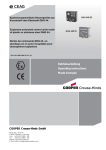
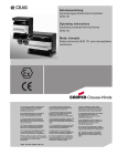
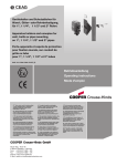
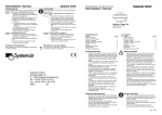
Explosionsgeschützte Klemmenkästen
aus Kunststoff GHG 72.
Explosion protected terminal boxes made
of plastic GHG 72.
Boites de jonction GHG 72. en plastique
pour atmosphères explosives
GHG 720 7001 P0001 D/E/F/ (L)
Betriebsanleitung
Operating instructions
Mode d’emploi
ĜĜ þ
!!"
#$%&'(
#&;
<
!,
!!"#$%&',
, ,(
)*+
,,!-
!%."!,,!!! )!
!!"#$%&'!/!
40!
!
!
=
!,
>
%!
! !
!
!!
!!"#$%&'
%%!!
!
!!
!!"#$%&'
!!
!
.%!
?@
!9!
ƳAnjǐ
,
ąąBą9,
!
,
!!"#$%&'
B
(
%00
!,
1
2!,
!!"#$%&'
(
?C@
Ɨ
!
Ɨ
!
!Ư
BƯ,Ɨ!
!"#$%&'Ɨ!
ƗƯBƗ(
345!
666
7 667
%.66
!!"#$%&'"
+A
,ƫ
B"DE",D
,ƫ ,ƫ!"!!Ī
F!!#$%&'EFĪ (
'8ǼĮȞȤȡİȚĮıșİȚ9:İIJĮ(ȡĮıȘIJȦȞȠįȘȖȚȦȞȤȡȘıİ
ȦȢıİĮȜȜȘȖȜȦııĮIJȘȢǼǼ9:ʌȠȡİȚȞĮȗȘIJȘșİȚĮʌȠ
IJȠȞǹȞIJȚʌȡȠıȦʌȠIJȘȢ!!"
#$%&'³
5?4!
,
,B!
!
!%."
D!,!,B.D!!"
#$%&'"!
,D!,,
COOPER Crouse-Hinds GmbH
Neuer Weg - Nord 49
D 69412 Eberbach / Germany
Fone +49 (0) 6271/806 - 500
Fax
+49 (0) 6271/806 - 476
Internet: http://www.CEAG.de
E-Mail: [email protected]
G0E!!
!HI
!H1!HI!
!
.I%!9
"
!!
!!"#$%&'
G?5ą
!JBá,DD
D!ĊDĪ<DüD
!
D
DE!!"!"
#$%&'!(
0%7!6
,
,"
7
!
%."!K
B B
6E!K%!!!"
#$%&'"!!
0*
B CC
!
;þ
!!"#$%&'C!(
0?L5!BC
!!
!!"#$%&'C
!(
Contents:
Inhalt:
1
1.1
2
3
4
5
6
6.1
6.2
6.3
6.4
6.5
6.6
7
8
9
10
Inhalt ......................................
Maßbild ..................................
Technische Daten .................
Kunststoffklemmenkästen ....
Sicherheitshinweise ..............
Normenkonformität ...............
Verwendungsbereich ............
Verwendung/
Eigenschaften ........................
Installation ..............................
Montage ................................
Öffnen des Gerätes/
Elektrischer Anschluss .........
Kabel- und Leitungseinführung; Verschlussstopfen ...................................
Flansch-u. Metallplatten ........
Schließen des Gerätes .........
Inbetriebnahme .....................
Instandhaltung / Wartung .....
Reparatur / Instand
setzung/ Änderungen ...........
Entsorgung / Wiederverwertung ............................
Strombelastungstabelle ........
2
3-5
3
3
4
4
4
4
4
5
1
1.1
2
3
4
5
6
6.1
6.2
5
6.3
6
6
6
6
7
6.4
6.5
6.6
7
8
9
10
7
7
18
Konformitätserklärung
separat beigelegt
2
Cooper Crouse-Hinds GmbH
Contents ................................
Dimensional drawings ...........
Technical data .......................
Plastic terminal boxes ...........
Safety instructions ................
Conformity with standards ...
Field of application ................
Application/ Properties .........
Installation ..............................
Mounting ................................
Opening the device /
Electrical connection .............
Cable entry (KLE);
blanking plug .........................
Flange and metal plates ........
Closing the device ................
Taking into operation .............
Maintenance/Servicing .........
Repairs/Modification ............
Disposal/Recycling ...............
Current load values ..............
Declaration of conformity,
enclosed separately.
Contenu:
2
8
8
8
9
9
9
9
10
10
10
11
11
11
11
12
12
12
18
1
1.1
2
3
4
5
6
6.1
6.2
6.3
6.4
6.5
6.6
7
8
9
10
Contenu .................................
Plans cotés ............................
Caractéristiques
techniques .............................
Boîtes de jonction en plastique
Consignes de sécurité ..........
Conformité avec les
normes ...................................
Domaine d’utilisation .............
Utilisation/Propriétés .............
Installation ..............................
Montage ................................
Ouverture de la boîte /
Raccordement électrique .....
Entrées de câble (KLE)
bouchons de fermeture ........
Plaques à bridges ................
Fermeture du couvercle .......
Mise en service .....................
Maintenance/Entretien ..........
Réparation/Remise
en état ....................................
Évacuation des déchets/
Recyclage .............................
Tableau de charge ................
Déclaration de conformité,
jointe séparément.
2
13
13
13
14
14
14
14
15
15
15
16
16
16
16
17
17
17
18
Explosionsgeschützte Klemmenkästen, Typ GHG 72.
Klemmenkasten GHG 721 1...
1
Technische Angaben
1.1 Kunststoffklemmenkästen GHG 721 ...
EG-Baumusterprüfbescheinigung:
BVS 13 ATEX E 013 X
Gerätekennzeichnung nach 94/9EG / und Norm:
ATEX
II 2 G Ex (d e mb) IIC T5* -55°C Ü Tamb Ü +55°C Gb
II 2 G Ex (d e mb) IIC T6* -55°C Ü Tamb Ü +40°C Gb
II 2 G Ex e ib [ia/ib] IIC T5* -55°C Ü Tamb Ü +55°C Gb
II 2 G Ex e ib [ia/ib] IIC T6* -55°C Ü Tamb Ü +40°C Gb
II 2 D Ex tb IIIC T80°C (T95°C) Db IP66
(*Abhängig von den eingebauten Komponenten)
IECEx Konformitätsbescheinigung:
Gerätekennzeichnung:
IECEx
IECEx BVS 13.0031X
Ex (d e mb) IIC T5* -55°C Ü Tamb Ü +55°C Gb
Ex (d e mb) IIC T6* -55°C Ü Tamb Ü +40°C Gb
Ex e ib [ia/ib] IIC T5* -55°C Ü Tamb Ü +55°C Gb
Ex e ib [ia/ib] IIC T6* -55°C Ü Tamb Ü +40°C Gb
Ex tb IIIC T80°C (T95°C) Db IP66
(*Abhängig von den eingebauten Komponenten)
Bemessungsspannung:
Bemessungsstrom:
Zulässige Umgebungstemperatur:
Abweichende Temperaturen sind bei Sonderversionen möglich)
Zul. Lagertemperatur in Originalverpackung:
Schutzart nach EN/IEC 60529:
Schutzklasse nach EN/IEC 61140:
Anschlussklemmen:
Klemmenkasten GHG 721 0...:
Klemmenkasten GHG 721 1...:
Leitungseinführung:
Leergewicht:
Klemmenkasten GHG 721 0...:
Klemmenkasten GHG 721 1...:
Prüfdrehmomente:
Deckelschrauben
Druckschraube der KLE M12
Druckschraube der KLE M16 - M20
Druckschraube der KLE M25
Druckschraube der KLE M32 - M 63
bis 690 V
siehe Tabelle im Gehäusedeckel
-55°C bis +40°C/+55°C (Listenausführung)
-55°C bis +55°C
IP 66 (Listenausführung)
I - wird von den Kunststoffklemmenkästen erfüllt.
II - mit Metallflansch
Anzahl - im Rahmen der Bescheinigung
max. 16 mm²
max. 35 mm²
laut Auftrag, im Rahmen der Bescheinigung
ca. 1,1 kg
ca. 1,7 kg
2,50
1,65
2,50
3,50
5,00
Nm
Nm
Nm
Nm
Nm
Maßbilder Kunststoffklemmenkästen
X = Befestigungsmaße
GHG 721 0
GHG 721 1
Cooper Crouse-Hinds GmbH
3
Explosionsgeschützte Klemmenkästen, Typ GHG 72.
2
Sicherheitshinweise
4
Zielgruppe dieser Anleitung sind
Elektrofachkräfte und Unterwiesene Personen in Anlehnung
an die EN/IEC 60079-14.
Die Kunststoffkästen sind zum Einsatz in
explosionsgefährdeten Bereichen der Zonen
1, 2 und 21, 22 gemäß
EN/IEC 60079-10-1 und
EN/IEC 60079-10-2 geeignet.
Die Klemmenkästen GHG 72. sind nicht
für Zone 0 und Zone 20 geeignet.
Die Anforderungen der EN/IEC 60079-31
u.a. in Bezug auf übermäßige Staubablagerungen und Temperatur, sind vom
Anwender zu beachten.
Die auf den Klemmenkästen angegebene
Temperaturklasse und Explosionsgruppe
ist zu beachten.
Umbauten oder Veränderungen an den
Klemmenkästen sind nicht gestattet. Sie
sind bestimmungsgemäß in unbeschädigtem und einwandfreiem Zustand zu
betreiben.
Als Ersatz und zur Reparatur dürfen nur
Originalteile von CEAG / Cooper CrouseHinds (CCH) verwendet werden.
Vor Inbetriebnahme müssen die Klemmenkästen entsprechend der im Abschnitt 6
genannten Anweisung geprüft werden.
Die eingesetzten Gehäusematerialien
einschließlich der außenliegenden Metallteile
bestehen aus hochwertigen Werkstoffen, die
einen anwendungsgerechten Korrosionsschutz und Chemikalienresistenz in "normaler
Industrieatmosphäre" gewährleisten:
- glasfaserverstärktes Polyester
- Edelstahl V 4A AISI 316 L
Bei einem Einsatz in extrem aggressiver
Atmosphäre, können Sie zusätzliche Informationen über die Chemikalienbeständigkeit der
eingesetzten Kunststoffe, bei Ihrer zuständigen Cooper Crouse-Hinds Niederlassung
erfragen.
5
Die Klemmenkästen dienen zum Verteilen von
elektrischer Energie, z.B. Lichtstromkreise ,
Heizstromkreise, Steuerstromkreise, eigensichere Stromkreise usw.. Temperaturklasse,
Explosionsgruppe, zulässige Umgebungstemperatur siehe technische Daten.
Die Klemmenkästen sind auch im "normalen
Industriebereich" verwendbar.
Beachten Sie die nationalen Sicherheitsund Unfallverhütungsvorschriften und die
nachfolgenden Sicherheitshinweise in
dieser Betriebsanleitung, die wie dieser
Text in Kursivschrift gefasst sind!
Verwendung zu berücksichtigen.
Legende
Sicherheitshinweise
Angaben aus Punkt 3 u. 4 sind bei der
Andere als die beschriebenen Anwendungen sind ohne schriftliche Erklärung
der Fa. CEAG / CCH nicht zulässig.
Beim Betrieb sind die in der Betriebsanleitung unter Punkt 7 genannten Anweisungen zu beachten.
Beachte
3
Normenkonformität
Das Betriebsmittel ist gemäß
DIN EN ISO 9001:2008 und
IEC 80079-34:2011 entwickelt, gefertigt und
geprüft worden.
Es entspricht den aufgeführten Normen, in
der separat beigelegten Konformitätserklärung.
94/9 EG: Geräte und Schutzsysteme zur
bestimmungsgemäßen Verwendung in
explosionsgefährdeten Bereichen.
Weitere Anforderungen wie die EG-Richtlinie
"Elektromagnetische Verträglichkeit"
(2004/108/EG) werden von den Klemmenkästen erfüllt.
Cooper Crouse-Hinds GmbH
Verwendung / Eigenschaften
Alle Fremdkörper müssen vor der ersten
Inbetriebnahme aus den Klemmenkästen
entfernt werden.
2.1
4
Verwendungsbereich
Die Verantwortung hinsichtlich
Eignung und bestimmungsgemäßer
Verwendung dieser Klemmenkästen unter
Bezugnahme der in der Anlage vorhandenen Rahmenbedingungen (s. technische
Daten) liegt allein beim Betreiber.
6
Installation
Für das Errichten / Betreiben sind die
relevanten nationalen Vorschriften sowie die
allgemein anerkannten Regeln der Technik
maßgebend.
Explosionsgeschützte Klemmenkästen, Typ GHG 72.
6.1
Bild 1
Montage
Die Montage der Klemmenkästen kann ohne
Öffnen der Gehäuse erfolgen.
A
Die Klemmenkästen dürfen bei der Direktmontage an der Wand nur an den vorgesehenen Befestigungspunkten eben aufliegen.
Die gewählte Schraube muss der
Befestigungsöffnung angepasst sein (siehe
Maßbilder, Seite 3) und sie darf die Öffnung
nicht beschädigen (z.B. Verwendung einer
Unterlegscheibe).
Die Klemmenkästen sind mit mindestens 2
Schrauben diagonal zu befestigen.
B
Bei übermäßigem Anziehen können
die Kunststoffklemmenkästen beschädigt
werden.
Die Kunststoffklemmenkästen GHG 721 0
und GHG 721 1 sind zur schraubenlosen
Befestigung auf den CEAG / CCH - Gerätehaltern geeignet (siehe Bild 4-7, Seite 6+7).
Die betreffende Montageanleitung ist
C
zu beachten.
6.2
Öffnen des Gerätes /
Elektrischer Anschluss
Der elektrische Anschluss des
Betriebsmittels darf nur durch Fachpersonal erfolgen (EN/IEC 60079-14).
D
DIe Luft- und Kriechstrecken nach
EN/IEC 60079-7; Tabelle 1 einhalten.
Die im Deckel der Klemmenkästen angegebene Strombelastungstabelle ist zu beachten.
Zur Aufrechterhaltung der Zündschutzart ist
der Leiteranschluss mit besonderer Sorgfalt
durchzuführen.
Bild 2
2
Bild 3
1
Bei Mischbestückungen Ex - e / Ex - i sind
die erforderlichen Mindestabstände einzuhalten (siehe z.B. EN/IEC 60079-11).
Nach der Demontage der Klemmentragschiene (zur leichteren Einführung der Kabel
und Leitungen), muss vor dem elektrischen
Anschluss die Klemmentragschiene wieder
ordnungsgemäß montiert werden.
Die Demontage und Montage erfolgt, wie
nachfolgend beschrieben:
Durch Auseinanderdrücken der seitlichen
Gehäusewände wird die Klemmentragschiene aus dem Gehäuseunterteil gelöst.
Zur Montage ist die Klemmentragschiene in
die Rastnocke einer Gehäuseseitenwand
einzusetzen. Danach wird die Schiene auf der
anderen Gehäuseseite eingeschnappt
(Siehe Bild 3).
Die PE-Schiene ist in 4 Positionen variabel
einbaubar (siehe Bild 1):
A
B
C
D
Gehäuseseite
Gehäuseseite
Gehäuseseite
Gehäuseseite
oben
oben
unten
unten
-
PE-Anschluss
PE-Anschluss
PE-Anschluss
PE-Anschluss
unten
oben
unten
oben
Die Montage ist wie folgt durchzuführen:
In die Führungsleisten, die in die Gehäuseseitenwände eingearbeitet sind, werden die
PE-Schienen bis zum Anschlag eingeschoben.
Achtung : Die Schiene muss in die
Aufnahme am Gehäuseboden einrasten.
Es ist darauf zu achten, dass die Einbaulage der PE-Schiene einen korrekten
LeiterAnschluss gewährleistet.
Wird das Betriebsmittel in der Ausführung
"Schutzisoliert" ausgeführt, kann das
entsprechende Klebeschild
(
) GHG 905 1002 P0005 beim Hersteller
angefordert werden.
Die Isolation muss bis an die Klemme
Wird die eingebaute Klemmentragschiene
heranreichen. Der Leiter selbst darf nicht
beschädigt sein.
Die minimal und maximal anschließbaren
Leiterquerschnitte sind zu beachten.
Alle Schrauben und/oder Muttern der
Anschlussklemmen, auch die der nicht
benutzten, sind fest anzuziehen.
Die eingebaute Standardklemme ist zum
Direktanschluss von Leitern mit Kupferadern
ausgelegt.
nicht komplett mit Reihenklemmen bestückt,
muss die Klemmentragschiene in den
Potentialausgleich mit einbezogen werden.
Bei eingebauten Bolzenklemmen sind
DIN - Kabelschuhe zu verwenden.
Achtung: Das Aufpressen der Kabelschuhe auf das Kabel ist fachgemäß
durchzuführen. Es ist sicherzustellen,
dass die erforderlichen Mindestluftstrecken eingehalten werden (bei 690V ->
12mm)
Cooper Crouse-Hinds GmbH
5
Explosionsgeschützte Klemmenkästen, Typ GHG 72.
6.3
Kabel-und Leitungseinführungen (KLE);
Verschluss-Stopfen
Es dürfen generell nur bescheinigte
KLE und Verschluss-Stopfen verwendet
werden. Für bewegliche Leitungen sind
Trompetenverschraubungen oder andere
geeignete Einführungen mit
zusätzlicher Zugentlastung zu verwenden.
Die für die eingebauten KLE maßgebenden Montagerichtlinien sind zu beachten.
Beim Einsatz von KLE mit einer niedrigeren als der für das Gerät zutreffenden IPSchutzart (Siehe Technische Daten,
Seite 3) wird die IP-Schutzart des gesamten Gerätes reduziert.
Nicht benutzte Einführungsöffnungen sind mit
einem bescheinigten Verschluss-Stopfen zu
verschließen, um die Mindestschutzart herzustellen.
Es ist darauf zu achten, dass bei der
Installation der KLE die für den Leitungsdurchmesser geeigneten Dichtungseinsätze
verwendet werden.
Bei ausschneidbaren Dichtungseinsätzen ist
sicherzustellen, dass der Einsatz ordnungsgemäß dem Leitungsdurchmesser angepasst
wird.
Alle nicht benutzten metrischen CEAG / CCH
KLE sind mit dem bescheinigten Verschluss
für metrische KLE zu verschließen.
Zur Sicherstellung der erforderlichen
Mindestschutzart sind die KLE fest anzuziehen.
Bei übermäßigem Anziehen kann die
6.5
Schutzart beeinträchtigt werden.
Achtung: Beim Anziehen der Hutmutter der Metall-KLE (Typ ADE 1F) ist die
Verschraubung mit einem geeigneten
Werkzeug gegen Verdrehen zu sichern.
6.4
Flansche und Metallplatten
Müssen Flanschplatten demontiert werden
(z.B. zum Bohren von Einführungsöffnungen),
ist bei der Montage zur Aufrechterhaltung der
Mindestschutzart auf den korrekten Sitz der
Flanschplatte und den Sitz des Befestigungsbügels zu achten.
Die Flanschplatten sind so zu montieren,
dass die IP-Schutzart gewährleistet bleibt.
Dabei ist auf den exakten Sitz und die
Unversehrtheit der Dichtung zu achten.
Von außen herangeführte PE-Leitungen sind auf die dafür vorgesehene PEKlemme am Flansch anzuschließen. Der
maximale Anschlussquerschnitt beträgt
50 mm².
Schließen des Gerätes /
Deckelverschluss
Alle Fremdkörper sind aus dem Gerät
zu entfernen.
Zur Sicherstellung der erforderlichen
Mindestschutzart sind die Deckelschrauben
fest anzuziehen.
Bei übermäßigem Anziehen kann die
Schutzart beeinträchtigt werden.
6.6
Inbetriebnahme
Vor Inbetriebnahme des Betriebsmittels sind
die in den einzelnen nationalen Bestimmungen genannten Prüfungen durchzuführen.
Außerdem ist vor der Inbetriebnahme die
korrekte Installation des Betriebsmittels in
Übereinstimmung mit dieser Betriebsanleitung und anderen anwendbaren Bestimmungen zu überprüfen.
Unsachgemäße Installation und
Betrieb der Klemmenkästen kann zum
Verlust der Garantie führen.
Achtung: Metallflansche, Metallplatten und Metallverschraubungen
müssen in den Potentialausgleich
miteinbezogen werden.
Werden Klemmenkästen mit Kunststoffflansche, im Rahmen der Baumusterprüfbescheinigung, bei Umgebungstemperaturen unter -40°C eingesetzt,
müssen diese bauseits vor unzulässigen
mechanischen Belastungen geschützt
werden.
Bild 4
Gerätehalter Größe 2A für Rohrbefestigung
Bild 5
Gerätehalter Größe 2A für Gitterrinnen- und
Wandbefestigung
C
Steckbefestigungslöcher für
Klemmenkasten GHG 721 0...
6
Cooper Crouse-Hinds GmbH
C
Steckbefestigungslöcher für
Klemmenkasten GHG 721 0...
Explosionsgeschützte Klemmenkästen, Typ GHG 72.
7
Instandhaltung / Wartung
Die für die Wartung / Instandhaltung von
Bild 6
Gerätehalter Grösse 3, horizontale Rohrbefestigung.
elektrischen Betriebsmitteln in explosionsgefährdeten Bereichen geltenden nationalen
Bestimmungen sind einzuhalten
(EN/IEC 60079-17).
Vor Öffnen des Gehäuses Spannungsfreiheit
sicherstellen bzw. geeignete Schutzmaßnahmen ergreifen.
Bei eigensicheren Stromkreisen ist das
Arbeiten unter Spannung zulässig.
Die erforderlichen Wartungsintervalle sind
anwendungsspezifisch und daher in Abhängigkeit von den Einsatzbedingungen vom
Betreiber festzulegen.
Im Rahmen der Wartung sind vor allem die
Teile, von denen die Zündschutzart abhängt,
zu prüfen (z.B. Unversehrtheit und Dichtheit
des Gehäuses, Unversehrtheit der Dichtungen und der Kabel- und Leitungseinführungen).
Es ist vor dem Schließen des Gehäusedeckels auf den korrekten Sitz des Niederhalters im Deckel und die Unversehrtheit des
Niederhalters zu achten (siehe Bild 2, Seite 5).
C
Kunststoffklemmenkästen in grau, bzw.
lackiert nur mit einem feuchtem Tuch reinigen!
Schraubbefestigungslöcher für Klemmenkasten GHG 721 1....
Sollte bei einer Wartung festgestellt werden,
dass Instandsetzungsarbeiten erforderlich
sind, ist Abschnitt 8 dieser Betriebsanleitung
zu beachten.
8
Reparatur / Instandsetzung /
Änderung
Bild 7
Gerätehalter Grösse 3, horizontale Gitterrinnen- und Wandbefestigung
Instandsetzungsarbeiten / Reparaturen
dürfen nur unter Verwendung von CEAG /
CCH Originalersatzteilen vorgenommen
werden.
Reparaturen, die den Explosionsschutz betreffen, dürfen nur von CEAG /
CCH oder einer qualifizierten Elektrofachkraft in Übereinstimmung mit
national geltenden Regeln durchgeführt
werden
(EN/IEC 60079-19).
Umbauten oder Änderungen am Betriebsmittel sind nicht gestattet; ausgenommen ist das
Anbringen von zusätzlichen KLE und das
Montieren von Anschlussklemmen im
Rahmen der Zulassung des Betriebsmittels.
9
Entsorgung /
Wiederverwertung
Bei der Entsorgung des Betriebsmittels sind
die jeweils geltenden nationalen Abfallbeseitigungsvorschriften zu beachten.
Zur Erleichterung der Wiederverwertbarkeit
von Einzelteilen sind Kunststoffteile mit dem
Kennzeichen des verwendeten Kunststoffes
versehen.
Programmänderungen und -ergänzungen
sind vorbehalten.
C
Steckbefestigungslöcher für Klemmenkasten GHG 721 1....
Cooper Crouse-Hinds GmbH
7
Explosion protected terminal boxes type, GHG 72.
Terminal box GHG 721 1...
1
Technical data
1.1 Plastic terminal boxes GHG 721 ...
ATEX type examination certificate
Marking acc. to 94/9/EG and standard:
ATEX
II 2 G
II 2 G
II 2 G
II 2 G
II 2 D
BVS 13 ATEX E 013 X
Ex (d e mb) IIC T5* -55°C Ü Tamb Ü +55°C Gb
Ex (d e mb) IIC T6* -55°C Ü Tamb Ü +40°C Gb
Ex e ib [ia/ib] IIC T5* -55°C Ü Tamb Ü +55°C Gb
Ex e ib [ia/ib] IIC T6* -55°C Ü Tamb Ü +40°C Gb
Ex tb IIIC T80°C (T95°C) Db IP66
(*Depending on the components installed)
IECEx type examination certificate:
Category of application:
IECEx
IECEx BVS 13.0031X
Ex (d e mb) IIC T5* -55°C Ü Tamb Ü +55°C Gb
Ex (d e mb) IIC T6* -55°C Ü Tamb Ü +40°C Gb
Ex e ib [ia/ib] IIC T5* -55°C Ü Tamb Ü +55°C Gb
Ex e ib [ia/ib] IIC T6* -55°C Ü Tamb Ü +40°C Gb
Ex tb IIIC T80°C (T95°C) Db IP66
(*Depending on the components installed)
Rated voltage:
Rated current:
Permissible ambient temperature:
Deviating temperatures possible with special versions.
Perm.storage temperature in original packing:
Protection category acc. to EN/IEC 60529:
Insulation class acc. to EN/IEC 61140:
Terminals:
Terminal box GHG 721 0...
Terminal box GHG 721 1...
Cable entries:
Empty weights:
Terminal box GHG 721 0... :
Terminal box GHG 721 1... :
Test torques:
Cover screws
Cap nut of the plastic cable entry M12
Cap nut of the plastic cable entry M16 - M20
Cap nut of the plastic cable entry M25
Cap nut of the plastic cable entry M32 - M 63
up to 690 V
acc. to table on the inside of the enclosure cover
-55° C to +55° C (catalogue version)
-55° C to +55° C
IP 66 (catalogue version)
I - plastic terminal boxes fulfil this requirement
II - with metal flange
Quantity - acc. to the certificate
max. 16 mm²
max. 35 mm²
acc. to customer´s specification and as certified
approx. 1.1 kg
approx. 1.7 kg
2.50
1.65
2.50
3.50
5.00
Nm
Nm
Nm
Nm
Nm
Dimensions, plastic terminal boxes
X = fixing dimensions
GHG 721 0
8
Cooper Crouse-Hinds GmbH
GHG 721 1
Explosion protected terminal boxes type, GHG 72.
2
Safety instructions
4
The operations must be carried out
by electrical suitably trained in
hazardous area with knowledge
of increased safty explosion
protection IEC/EN 60079-14.
The plastic terminal boxes are suitable for
use in Zone 1, 2 and 21, 22
hazardous areas acc. to
IEC/EN 60079-10-1 and IEC/EN 60079-10-2.
The terminal boxes GHG 72. are not
suitable for Zone 0 and Zone 20
hazardous areas.
The requirements of the IEC/EN 60079-31
regarding excessive dust deposits and
temperature to be considered from the
user.
The temperature class and explosion
group marked on the terminal boxes have
to be observed.
Modifications to the terminal boxes or
changes of their design are not permitted.
They shall to be used for their intended
purpose and in perfect and clean condition.
For replacement and repair only genuine
CEAG / CCH spare parts may be used.
Prior to taking the terminal boxes into
operation, they shall be checked in
accordance with the instruction as per
section 6.
Before the initial operation, any foreign
matter will have to be removed from the
terminal boxes.
Observe the national safety rules and
regulations for prevention of accidents as
well as the safety instructions included in
these operating instructions and set in
italics the same as this text!
2.1
Legend
Safety warning
Field of application
The enclosure materials employed, including
the exterior metal parts, are made of highquality materials which ensure a corrosion
protection and resistance to chemical substances corresponding to the requirements in
a "normal industrial atmosphere":
- glass-fibre reinforced polyester
- special stainless steel V4 A AISI 316 L
In case of use in an extremely aggresive
atmosphere, please refer to manufacturer
5
Use / Properties
The terminal boxes are intended for the
distribution of electrical energy, e.g. light
circuits, heating circuits, control circuits,
intrinsically safe circuits etc..
As to temperature class, explosion group,
permissible ambient temperature, see
technical data.
The terminal boxes can also be used in a
„normal industrial area“.
The data as per point 3 and 4 shall be
taken into account with the use.
Applications other than described are
not permitted without CEAG / CCH’s prior
written consent.
For the operation, the instructions stated
in section 7 of the operating instructions
shall be observed.
The user alone is responsible for the
appropriate use of this installation switch
in consideration of the basic conditions
existing at the plant (see technical data).
Note
3
Conformity with standards
The apparat is conform to the standards
specified in the EC-Declaration of conformity,
enclosed separately.
It has been designed, manufactured and
tested according to the state of the art and to
DIN EN ISO 9001:2008 and
IEC 80079-34:2011.
94/9 EC: Equipment and protective systems
intended for use in potentially explosive
atmospheres.
The terminal boxes also fulfil further
requirements such as those of directive on
electromagnetic compatibility (2004/108/EC).
Cooper Crouse-Hinds GmbH
9
Explosion protected terminal boxes type, GHG 72.
6
Fig. 1
Installation
For the mounting and operation, the
respective national regulations as well as the
general rules of engineering shall be
observed.
A
6.1
Mounting
The plastic boxes can be mounted without
opening their enclosure.
When mounting the terminal boxes directly
onto the wall, they shall rest evenly only on
the fastening points provided for them. The
chosen screw must match the fastening hole
(see dimensional drawings page 8) and
they shall not damage the hole (e.g. use of a
washer).
B
The terminal boxes must be fastened
diagonally by means of at least 2 screws.
If the screws are overtightened, the
plastic terminal boxes may be damaged.
The plastic terminal boxes GHG 721 0 and
GHG 721 0 are suitable for fastening onto
CEAG / CCH apparatus holders by means of
self-cutting screws and clip-on mounting (see
fig. 4 - 7, page 11 + 12).
C
The respective mounting instructions
will have to be observed.
The fitted standard terminals are designed
for direct connection of conductors with
copper cores.
If stud terminals are fitted, DIN cable lugs
shall be used.
Attention: The cable lugs should be
crimped onto the cable in a workmanlike
manner. It is to be ensured that the
required min. air gaps are kept
(at 690V ->12mm).
In case of mixed equipment Ex e / Ex-i, the
required minimum distances will have to be
kept (see e.g. IEC/EN 60079-11).
After removing the terminal rail (in order to
facilitate the entry of cables), the terminal rail
shall again be propperly put in place before
establishing the electrical connection.
Removal and mounting of the terminal rail are
performed as follows:
By pressing apart the enclosure sides, the
terminal rail can be detached from the bottom
part of the enclosure. In order to install the
terminal rail, it is fitted onto the catch on one
side of the enclosure wall and then snapped
in on the opposide enclosure wall (see fig. 3).
The PE rail can optionally be fitted in 4
positions (see fig.1):
6.2
D
Opening the apparatus/
Electrical connection
The electrical connection of the
apparatus may only be carried out by
skilled staff (IEC/EN 60079-14).
The minimum clearances and creepage
distances in accordance with
EN/IEC 60079-7, Table 1, shall be
observed.
Fig. 2
The table indicating the current load values
which is provided on the cover inside of the
terminal boxes is to be observed.
2
1
In order to maintain the mode of protection,
the conductors will have to be connected with
special care.
The insulation shall reach up to the
terminal. The conductor itself shall not be
damaged.
Fig. 3
The connectible min. and max. conductor
cross-sections will have to be observed.
All screws and/or nuts of the supply
terminals, and unused terminals, shall be
tightened down.
10
Cooper Crouse-Hinds GmbH
A Enclosure top side
- PE-connection bottom
B Enclosure top side
- PE-connection top
C Enclosure bottom side- PE-connection bottom
D Enclosure bottom side- PE-connection top
The PE rail is fitted as follows:
It has to be pushed home in the respective
guide rails that are integrated into the lateral
enclosure walls.
Attention: Care has to be taken that
the PE rail has such a position that a
proper conductor connection is ensured.
In the case of building up the electrical
equipment in the "protective insulation"
version, appropriate sticker
(
) GHG 905 1002 P0005 can be
requested by the manufacturer.
If the inserted terminal rail is not equipped
completely with line-up terminals, the terminal
rail must be included in the equipotential
earth connection also.
Explosion protected terminal boxes type, GHG 72.
6.3
Cable entries (KLE)/
Blanking plugs
Generally, only certified cable entries
and blanking plugs may be used. Flexible
cables are to be used with trumpetshaped cable glands or other suitable
entries with additional pull-relief.
The mounting directives applicable to the
fitted cable entries are to be observed.
When using cable entries with a lower IP
protection than that which applies to the
device (see technical data) the IP
protection of the whole device will be
reduced.
In order to establish the minimum protection
category, unused holes have to be closed
with a certified blanking plug.
Care has to be taken that when fitting the
cable entries, sealing inserts appropriate to
the cable diameter are used.
In case of sealing inserts that are cut out, it
will have to be ensured that the insert is
properly adapted to the cable diameter.
All vacant metric CEAG / CCH cable entries
are to be closed with the certified blanking
plug for metric cable entries.
In order to ensure the required minimum
protection category, the cable glands shall be
tightened down.
Overtightening might impair the
Attention: When tightening the cap
6.5
nut of the type ADE 1F metal cable entry,
the screwing is to be protected against
twisting by means of a suitable tool.
6.4
Closing the device/
cover closure
Any foreign matter is to be removed
from the apparatus.
Flange and metal plates
If flange plates have to be removed in case of
plastic terminal boxes (e.g. for drilling entry
holes), attention will have to be paid to the
proper fit of the flange plate and of the clamp
clip when mounting them in order to maintain
the minimum protection category.
Flange plates for stainless steel terminal
boxes shall be fitted so that the IP protection
in maintained. Pay attention to the proper
seat of the sealing element.
PE conductors fed from outside are to
be connected to the PE terminal provided
on the flange. The maximum crosssection is 50mm².
Attention: Metal flanges, metal plates
and metal cable glands shall be included
in the equip potential earth connection.
In order to ensure the required minimum
protection category, the cover screws are to
be tightened down.
Overtightening might impair the
protection category.
6.6
Taking into operation
Prior to taking the apparatus into operation,
the tests specified in the relevant national
regulations will have to be carried out. Apart
from that, the correct functioning and
installation of the apparatus in accordance
with these operating instructions and other
applicable regulations will have to be
checked.
Incorrect installation and use of the
terminal boxes can invalidate the
guarantee.
If terminal boxes with plastic flanges are
used within the scope of the type examination
certificate in ambient temperatures below 40°C, they shall be installed in such a way
that they are protected against inadmissible
mechanical loads.
protection category.
Fig. 5
Apparatus holder size 2A for channel- and wall mounting
Fig. 4
Apparatus holder size 2A for pipe mounting
C
Clamp fastening holes for
terminal box GHG 721 0...
C
Clamp fastening holes for
termional box GHG 721 0...
Cooper Crouse-Hinds GmbH
11
Explosion protected terminal boxes type, GHG 72.
7
Maintenance / Servicing
Fig. 6
Apparatus holder, size 3 for pipe mounting, horizontally
The relevant national regulations
which apply to the maintenance/repair of
electrical apparatus in explosive
atmospheres, will have to be observed
(IEC/EN 60079-17).
Before opening the enclosure make
sure that the terminal box is disconnected
from the voltage, or take the appropriate
protective measures.
In case of intrinsically safe circuits, working is
permitted while voltage applies.
The required maintenance intervals depend
on the specific application and will therefore
have to be determined by the user
dependent on the conditions of use.
When servicing the apparatus, particularly
those parts that are decisive for the type of
protection against explosion, will have to be
checked (e.g. intactness and tightness of the
enclosure, efficacy of the gaskets and the
cable entries).
Before closing the enclosure cover, pay
attention to the correct position and
intactness of the holding-down clamps (see
fig. 2, page 10).
C
Screwed fastening holes for terminal boxes GHG 721 1....
Grey or painted plastic terminal boxes shall
only be cleaned with a damp cloth.
If during servicing, repairs prove to be
necessary, section 8 of these operating
instructions will have to be observed.
8
Fig. 7
Apparatus holder, size 3 for channel- and wall mounting, horizontally
Repairs / Overhaul /
Modifications
Overhaul and repairs may only be carried out
with genuine CEAG / CCH spare parts.
Repairs that affect the explosion
protection, may only be carried out by
CEAG / CCH or a qualified electrician in
compliance with the applicable national
rules (IEC/EN 60079-19).
Modifications to the apparatus or changes of
its design are not permitted, except for the
mounting of additional cable entries and the
installation of supply terminals in accordance
with the approval of the apparatus.
9
Disposal / Recycling
When the apparatus is disposed of, the
respective national regulations on waste
disposal will have to be observed. In order to
facilitate the recycling of individual
components, plastic parts are provided with
the identification mark of the plastic material
used.
Subject to modifications or supplement of the
product range.
12
Cooper Crouse-Hinds GmbH
C
Clamp fastening holes for terminal boxes GHG 721 1....
Boites de jonction type GHG 72. pour atmosphères explosives
Boite de jonction GHG 721 1...
1
Caractéristiques techniques
1.1 Boites de jonction en plastique GHG 721 ...
ATEX Certificat de Conformité:
Marquage selon 94/9/CE et directive:
ATEX
BVS 13 ATEX E 013 X
II 2 G
II 2 G
II 2 G
II 2 G
II 2 D
Ex (d e mb) IIC T5* -55°C Ü Tamb Ü +55°C Gb
Ex (d e mb) IIC T6* -55°C Ü Tamb Ü +40°C Gb
Ex e ib [ia/ib] IIC T5* -55°C Ü Tamb Ü +55°C Gb
Ex e ib [ia/ib] IIC T6* -55°C Ü Tamb Ü +40°C Gb
Ex tb IIIC T80°C (T95°C) Db IP66
(*En fonction des composants installés)
IECE x Certificat de Conformité:
Marquage selon:
IECEx
IECEx BVS 13.0031X
Ex (d e mb) IIC T5* -55°C Ü Tamb Ü +55°C Gb
Ex (d e mb) IIC T6* -55°C Ü Tamb Ü +40°C Gb
Ex e ib [ia/ib] IIC T5* -55°C Ü Tamb Ü +55°C Gb
Ex e ib [ia/ib] IIC T6* -55°C Ü Tamb Ü +40°C Gb
Ex tb IIIC T80°C (T95°C) Db IP66
(*En fonction des composants installés)
Tension nominale:
Courant nominal:
Température ambiante admissible:
jusqu’à 690V
voir tableau à l’intérieur du couvercle
-55°C à +55°C (modèles de liste)
D’autres températures possibles avec des modèles spéciaux.
Temp. de stockage dans l’emballage original:
Indice de protection selon CEI/EN 60529:
Classe d’isolation selon CEI/EN 61140
Bornes de raccordement:
Boite de jonction GHG 721 0...
Boite de jonction GHG 721 1...
Entrées de câble:
Poids à vide:
Boite de jonction GHG 721 0... :
Boite de jonction GHG 721 1... :
Couples de serrage testés:
Vis du couvercle
Chapeau PE polyamide M12
Chapeau PE polyamide M16
Chapeau PE polyamide M20
Chapeau PE polyamide M25
Chapeau PE polyamide M32
Chapeau PE polyamide M40
Chapeau PE polyamide M50
Chapeau PE polyamide M63
-55°C à +55°C
IP 66 (modèles de liste)
Class I pour les BJ avec plaque laiton
Class II pour les BJ avec PE polyamide
Quantité - selon le certificat
16 mm²
au maxi
35 mm²
au maxi
selon spécification du client et certificat
env. 1,1 kg
env. 1,7 kg
2,50
1,65
2,50
2,50
3,50
5,00
5,00
5,00
5,00
Nm
Nm
Nm
Nm
Nm
Nm
Nm
Nm
Nm
Dimensions boites de jonction en plastique
X = dimensions de fixation
GHG 721 0
GHG 721 1
Cooper Crouse-Hinds GmbH
13
Boites de jonction type GHG 72. pour atmosphères explosives
2
Consignes de sécurité
Le groupe d’explosion et la classe
de température marqués sur les
appareils devront être respectés
(CEI/EN 60079-14).
Les boites de jonction GHG 72. ne
conviennent pas pour une utilisation en
zones 0 et 20.
Les exigences des CEI/EN 60079-31 en ce
qui concerne les dépôts de poussière
excessifs et la température doivent être
considérées par I’utilisateur.
Il n’est pas permis de transformer ou de
modifier les boites de jonction.
Seules des boîtes de jonction intactes
devront être employées pour la fonction
qui leur est dévolue.
Seules des pièces de rechange
homologuées d’origine CEAG / CCH
devront être utilisées comme
remplacement et pour des réparations.
Les réparations qui portent sur la
protection contre l’explosion, ne devront
être exécutées que par CEAG / CCH ou
par un électricien qualifié en conformité
avec la règlementation nationale en
vigueur.
Avant la mise en service, les
boites
de jonction doivent être vérifiées selon
l’instruction donnée dans la section 6.
Avant la première mise en service, tout
corps étranger doit être retiré de la boite
d e jonction.
Respectez les prescriptions nationales de
sécurité et de prévoyance contre les
accidents ainsi que les consignes de
sécurité de ce mode d’emploi en italique
comme ce texte.
2.1
Légende
Instructions de sécurité
Remarque
3
Conformité avec les normes
Les Appareils ont été conçus, fabriqués et
contrôlés suivant DIN EN ISO 9001:2008 et
IEC 80079-34:2011.
De plus, les boites de jonction répondent à
d’autres exigences comme par exemple,
celles de la directive CE “Compatibilité
électromagnétique” (2004/108/CE).
94/9 CE: Appareils et systèmes de protection
destinés à être utilisés en atmosphère explosible.
Les boîtes à jonction sont conformes aux
normes reprises dans la déclaration de
conformité, jointe séparément.
14
Cooper Crouse-Hinds GmbH
4
Domaine d’utilisation
Les boites de jonction en plastique on en
acier inoxydable conviennent à l’emploi en
les zones 1, 2 et zones 21, 22 d’une
atmosphère explosive selon
CEI/EN 60079-10-1 et
CEI/EN 60079-10-2!
Pour l’enveloppe et les pièces métalliques
extérieures, des matières de qualité
supérieure ont été employées qui assurent
une protection appropriée contre la corrosion
et une résistance contre des agents
chimiques en “atmosphère industrielle
normale”:
- polyester renforcé en fibres de verre
- acier inoxydable V 4A AISI 316 L
En cas d‘utilisation en atmosphère
extrèmement corrosive, vous pouvez obtenir
des informations complémentaires sur la
résistance chimique des plastiques utilisés
chez la succursale Cooper Crouse-Hinds de
votre région.
5
Utilisation / Propriétés
Les boites de jonction servent à la
distribution de l’énergie électrique, p.e. des
circuits d’éclairage, des circuits de
chauffage, des circuits de commande, des
circuits à sécurité intrinsèque etc. Quant à la
classe de température, le groupe d’explosion
et la température ambiante admissible, voir
les caractéristiques techniques.
Les boites de jonction peuvent aussi être
employées en "atmosphère industrielle
normale".
Pour l’utilisation, les consignes des
sections 3 et 4 devront être respectées.
Les utilisations autres que celles
décrites ne sont admises qu’avec le
consentement écrit de CEAG / CCH. Lors
de l’utilisation, les instructions selon
point 7 de ce mode d’emploi doivent être
respectées.
La responsabilité de qualification et la
bonne utilisation de ces boites à jonction
incombe à l’utilisateur seul.
Boites de jonction type GHG 72. pour atmosphères explosives
6
Fig. 1
Installation
Pour l’installation et l’exploitation de ces
appareils, la règlementation nationale en
vigueur ainsi que les règles de la technique
généralement reconnues devront être
respectées.
A
6.1
Montage
Le montage de boites de jonction peut se
faire sans ouvrir l’enveloppe.
En cas de jonction ne doivent reposer que
sur les points de fixation prévus. La vis
choisie doit être en rapport avec le trou de
fixation (voir plan coté page 13) et elle ne doit
pas endommager le trou (par ex. emploi
d’une rondelle).
B
Les boites de jonction doivent être fixées en
diagonale avec au moins 2 vis.
Si les vis sont forcées, l’appareil peut
être endommagé.
C
Les distances minimales d’isolement
préconisées dans la norme
CEI/EN 60079-7, tableau 1, doivent être
respectées.
Les valeurs de charge électrique du tableau
qui se trouve sur la face interne du
couvercle, doivent être respectées.
Afin de maintenir le mode de protection, la
connexion des conducteurs doit se faire très
soigneusement.
L’isolation doit couvrir le conducteur
Fig. 3
En cas d’équipement mixte Ex-e/Ex-i, les
espaces minimums requis doivent être
respectés (voir p.e. CEI/EN 60079-11).
Après avoir enlevé le rail DIN (afin de faciliter
l’introduction des câbles), celui-ci devra être
remis en place avant le raccordement
électrique.
La barrette de terre peut être montée
facultativement en 4 positions (voir fig. 1).
Ouverture de l’appareil /
Raccordement électrique
l’appareil ne doit se faire que par une
personne qualifiée (CEI/EN 60079-14).
1
Attention: Les cosses de câble
doivent être emmanchées par pression
sur le câble de manière appropriée. Il faut
veiller à ce que les entrefers minimaux
requis soient respectés (à 690V -> 12mm).
6.2
Le raccordement électrique de
2
En cas de bornes à tige, il faut utiliser des
cosses de câble selon DIN.
montage devront être respectées.
Les instructions respectives pour le
Fig. 2
La borne standard installée est prévue pour
le raccordement direct des conducteurs au
cuivre.
Le démontage et le montage se font comme
suit:
En écartant les parois láterales du boitier, le
rail DIN peut être détaché de la partie
inférieure du boitier. Pour monter le profilé
support, il est mis sur la came d’arrêt sur l’un
côté de la paroi du boitier. Puis, on le fait
encliqueter sur l’autre côté du boitier (voir fig. 3).
Les boites de jonction en plastique GHG 721
0 et GHG 721 1 sont conçues pour le
montage sans vis sur des plaques de
montagesur tube taille 3, voir fig. 4 à 7, page
16-17).
D
Toutes les vis et/ou écrous des bornes de
connexion, aussi celles des bornes non
utilisées, doivent être serrées à fond.
A
B
C
D
Face
Face
Face
Face
supérieure
supérieure
inférieure
inférieure
-PE
-PE
-PE
-PE
connexion en bas
connexion en haut
connexion en bas
connexion en haut
La barrette de terre est montée comme suit:
La barrette doit être poussée jusqu’à la
butée dans les règlettes de guidage
intégrées dans les parois latérales du boitier.
Attention: La barrette doit
s'encliqueter dans le logement au fond
du boitier.
Il faut faire attention à ce que la barrette
de terre soit placée de telle manière
qu’un raccordement correct des
conducteurs soit assuré.
Si la classe d'isolation est type II (double
jusqu’à la borne. Le conducteur lui-même
ne doit pas être endommagé.
isolation), l'autocollant avec le symbole
( ) GHG 905 1002 P0005 pourra être
obtenu auprès du fabricant
Les sections minimales et maximales
admissibles des conducteurs doivent être
respectées (voir caractéristiques
techniques).
de bornes, alors il doit être raccordé au
circuit équipotentiel de mise à la terre.
Si le rail DIN n'est pas totalement équipé
Cooper Crouse-Hinds GmbH
15
Boites de jonction type GHG 72. pour atmosphères explosives
6.3
Entrées de câble (KLE) /
Bouchons de fermeture
Les entrées de câble doivent être serrées à
fond pour maintenir l’indice de protection
minimum.
Généralement, seuls des bouchons de
fermeture et des entrées de câble certifiés
doivent être utilisés. Pour des câbles
flexibles il faudra utiliser des presseétoupes en forme de trompette ou
d’autres entrées appropriées avec
amarrage supplémentaire.
Lorsque des entrées de câble avec un
indice de protection IP inférieur à celui de
la boite de jonction sont employées (voir
Caractéristiques techniques, page 13),
l’indice de protection IP de l’ensemble
sera réduit.
Les directives pour le montage qui
s’appliquent aux entrées de câble utilisées,
doivent être respectées.
Les entrées de câble non utilisées doivent
être fermées avec un bouchon de fermeture
certifié pour établir l’indice de protection
minimum.
Lors du montage des entrées de câble il
faudra veiller à ce que des garnitures
d’étanchéité correspondant au diamètre du
câble soient utilisées.
En cas de garnitures qui doivent être
coupées sur mesure, il faudra faire attention
à ce que la garniture soit adaptée au
diamètre du câble.
Toutes les entrées de câble métriques CEAG
/ CCH non utilisées doivent être fermées
avec un bouchon de fermeture certifié pour
des entrées de câble métriques.
Au cas où elles seraient forcées, cela
pourrait être nuisible à l’indice de
protection.
Attention: Lors du serrage du
chappeau de l'entrée de câble métallique
du type ADE 1F, il faudra maintenir le
corps du presse étoupe à l'aide d'une clé
adaptée.
6.4
Plaques amovibles
Si les plaques amovibles doivent être
démontées (pour le percage d’entrées de
câble, par exemple) il faudra veiller lors du
montage au maintien de l’indice de protection
en replacant correctement la plaque ainsi
que la pièce rouge de maintien.
Les plaques amovibles des boites en acier
inoxydable sont montées de telle facon que
l’indice de protection IP soit respecté. Il faut
également veiller au bon logement du joint
d’étanchéité.
Les conducteurs de terre amenés de
l’extérieur doivent être connectés à la
borne PE prévue à cet effet sur la bride. La
section maximale est de 50 mm"
Attention: les plaques amovibles en
Si les boîtes de jonction avec plaques
plastiques amovibles sont utilisées dans le
cadre de la certification avec des
températures ambiantes inférieures à -40°C,
elles devront être installées de manière à être
protégées contre tout effort mécanique.
6.5
Fermeture du couvercle
Tout corps étranger doit être ôté de
l’appareil.
Les vis de couvercle doivent être serrées à
2.5 Nm afin de maintenir l’indice de protection
minimum.
Si les vis sont forcées, cela peut être
nuisible à l’indice de protection.
6.6
Mise en service
Avant la mise en service de l’appareil, les
vérifications spécifiées dans les règlements
nationaux individuels devront être exécutées.
De plus, il faudra vérifier la conformité du
montage avec ce mode d'emploi et avec les
autres réglementations en vigueur.
L’installation ou l’utilisation
incorrecte de ces boites à jonction peut
entraîner la perte de la garantie.
laiton, les plaques métalliques internes,
et les presse-étoupe métalliques doivent
être reliés au même potentiel.
Fig. 5
Plaque de montage taille 2A pour fixation au mur et sur
chemin de câble
Fig. 4
Plaque de montage taille 2A pour fixation sur tube
C
Trous de fixation pour boite de
jonction GHG 721 0
16
Cooper Crouse-Hinds GmbH
C
Trous de fixation pour boite de
jonction GHG 721 0
Boites de jonction type GHG 72. pour atmosphères explosives
7
Maintenance/Entretien
La règlementation nationale en
Fig. 6
Plaque de montage, taille 3 pour fixation sur tubes, horizontalement
vigueur pour la maintenance
et l’entretien du matériel électrique pour
atmosphère explosive doit être respectée
(CEI/EN 60079-17).
Avant d’ouvrir l’enveloppe, mettre le
boitier hors tension ou prendre des
mesures préventives appropriées.
En cas de circuits à sécurité intrinsèque, des
travaux sont permis sous tension.
Les intervalles de service requis dépendent de
l’emploi spécifique et devront donc être fixés par
l’utilisateur en tenant compte des conditions
d’utilisation.
Lors de l’entretien des boîtes, surtout les
composants qui sont essentiels à leur mode de
protection contre l’explosion, doivent être vérifiés
(par ex. intégrité des composants antidéflagrants
et du boîtier, efficacité des joints de couvercle et
serrage des entrées de câble).
Avant de fermer le couvercle, veillez à ce que les
2 pattes de maintien du rail DIN soient bien en
place et en bon état (voir fig. 2, page 15).
Les boites de jonction grises ou avec
peinture doivent être nettoyées uniquement
avec un chiffon humide.
C
Trous de fixation pour boite de jonction GHG 721 1...
Si, lors d’un entretien, on constate que des
travaux d’entretien sont nécessaires, il faudra
suivre le point 8 de ce mode d’emploi.
8
Réparations/Remise en état/
Modification
Les réparations ne doivent être exécutées
qu’à l’aide des pièces de rechange d’origine
CEAG / CCH.
Fig. 7
Plaque de montage taille 3 pour fixation au mur et sur chemin de câble,
horizontalement
Les réparations qui portent sur la
protection contre l’explosion, ne devront
être exécutées que par CEAG / CCH ou
par un électricien qualifié en conformité
avec la règlementation nationale en
vigueur (CEI/EN 60079-19).
Il n’est pas permis de transformer ou de
modifier ces appareils, sauf pour le montage
d'entrées de câbles supplémentaires ou de
bornes de raccordement en conformité avec
le certificat ATEX.
9
Évacuation des déchets/
Recyclage
Lors de l’évacuation de ce matériel
électrique, la règlementation nationale
respective en vigueur devra être respectée.
Pour faciliter la réutilisation des composants
individuels, des pièces en matière plastique
ont été repérées de la marque distinctive de
la matière plastique employée.
C
Trous de fixation pour boite de jonction GHG 721 1...
Sous réserve de modification ou
d’informations supplémentaires.
Cooper Crouse-Hinds GmbH
17
10
Strombelastungstabelle
Current load values
165 mm x 165 mm x 131 mm
GHG721 0 ... . ….
I/
A
3
6
10
16
20
25
35
50
63
80
100
125
160
200
225
250
315
400
500
Tableau de charge
ز/mm²
1,5
61
21
8
2,5
4
6
10
16
25
35
50
70
95
120
150
185
240
4)
40
23
11
45
25
7
49
19
2
48
15
5
40
18
7
5)
3)
1)
2)
285 mm x 165 mm x 131 mm
GHG721 1 ... . ….
I/
A
3
6
10
16
20
25
35
50
63
80
100
125
160
200
225
250
315
400
500
ز/mm²
1,5
65
22
9
1)
2)
18
Cooper Crouse-Hinds GmbH
2,5
4
6
10
16
25
35
50
70
95
120
150
185
240
4)
43
25
12
48
27
8
53
20
3
51
16
5
42
19
7
5)
3)
10
Strombelastungstabelle
Current load values
Tableau de charge
Anmerkungen
Note:
Remarques
1) max. Anzahl der Leiter in Abhängigkeit
vom Querschnitt und dem zulässigen
Dauerstrom für vorgenannte Gehäusetype. Als Leiter zählt jeder eingeführte
Leiter und jeder interne Verbindungsleiter.
Brücken und Schutzleiter werden nicht
gezählt.
1)
max. number of conductors depending
on the cross-section and allowed
continuous current for the mentioned
apparatus type. The number of
conductors is the sum of all incoming
conductors and internal wire
connections. Bridge links and earth
conductors do not count.
1)
nombre max. de conducteurs en fonction
de la section et du courant permanent
admissible pour le type de boîtier
précité. Est compté comme conducteur
tout conducteur introduit et tout
conducteur de liaison interne.
Les ponts et conducteurs de protection
ne sont pas comptés.
2) max. Klemmenzahl in Abhängigkeit von
obengenannter Gehäusetype und der
max. Anzahl der Leiter.
2)
max. number of terminals depending on
the above mentioned apparatus type
and the amx. number of conductors.
2)
nombre max. de bornes en fonction du
type de boîtier mentionné ci-dessus et
du nombre max. de conducteurs.
3) max. Klemmenzahl in Abhängigkeit von
obengenannter Gehäusetype und der
eingebauten 2-Leiter-Klemme.
3)
max. number of terminals depending on
the above mentioned apparatus type
and the built-in 2 wire terminals.
3)
nombre max. de bornes en fonction du
type de boîtier mentionné ci-dessus et
de la borne 2 fils intégrée.
To determine the permissible continuous
current for the selected conductor
cross-section, the max. rated current for
the terminal used and the connected
conductors must be observed.
Conductors used within the enclosure
must be suitable for a temperature of 70
– 80°C. Mixed circuits of different crosssections and currents are possible by
using the table values in the respective
proportions.
Bei der Auswahl der zulässigen Dauerströme für die Querschnitte sind die
max. Belastungsströme, der verwendeten Klemmen und der angeschlossenen
Kabel- und Leitungen zu beachten.
Leitungen, im Inneren der nach obiger
Tabelle bestückten Gehäuse, müssen
für eine Temperatur von 70 - 80 °C
geeignet sein. Mischbestückungen von
Stromkreisen unterschiedlicher Querschnitte und Ströme sind durch anteilige
Ausnutzung der Tabellenwerte möglich.
Beispiel:
Example:
Querschnitt / mm²
Cross section / mm²
Section / mm²
2,5
16
Strom / A
Current / A
Courant / A
10
35
Lors de la sélection des courants
permanents admissibles pour les
sections, on doit tenir compte des
courants de charge max., des bornes
utilisées et des câbles et lignes
raccordés. Les lignes à l’intérieur des
boîtiers équipés selon le tableau ci-dessus
doivent convenir pour une température de
70 - 80 °C. Les équipements mixtes de
circuits électriques de sections et courants
différents sont possibles moyennant
l’application correspondante des valeurs
du tableau.
Exemple:
Anzahl
Quantity
Nombre
Auslastung
Quantity Utilisation
Charge
28 (von 40)
6 (von 40)
= 70,0 %
= 15,0 %
Summe
Total
Somme
= 85,0 % <100%
Lors de l’application de ces valeurs de
tableau, les facteurs de simultanéité ou
les facteurs d’utilisation de
dimensionnement suivant CEI/EN 60439
peuvent être pris en compte. La valeur
du tableau est prévue pour une
température ambiante de 40 °C.
Réduction en cas de température plus
élevée, voir instructions de service.
When using this table the simultaneous
factor or the rated load factor in
accordance with IEC/EN 60439 may be
taken into consideration. The table
values are given for an ambient
temperature of 40°C. Reductions for
higher temperatures see operating
instructions.
Bei der Anwendung dieser Tabellenwerte, dürfen Gleichzeitigkeitsfaktoren
oder Bemessungsbelastungsfaktoren
entsprechend der EN/IEC 60439
berücksichtigt werden. Der Tabellenwert
ist für eine Umgebungstemperatur von
40 °C bemessen. Reduktion bei höheren
Temperaturen siehe Betriebvorschrift.
4)
In diesem Bereich kann unter Beachtung
der Hinweise und der festgelegten
Einbaumaße im Gehäuse beliebig
zusätzlich bestückt werden.
4)
In this range as many terminals can
be added as physically fit the available
mounting dimension and according to the
instructions.
5)
Bestückungen in diesem Bereich
erfordern einen gesonderten
Erwärmungsnachweis.
4) Dans cette zone, on peut prévoir un
équipement supplémentaire à volonté à
condition de tenir compte des indications
et des dimensions de montage définies
dans le boîtier.
5)
The terminal content in this range
requires a power dissipation test report
from the manufacturer.
5)
Bestückungsvarianten mit kleineren oder
größeren Querschnitten als in diesen
Tabellen aufgeführt, wurden nicht gemessen.
Sie sind in Verbindung mit den zulässigen
Dauerströmen gesondert zu betrachten und
erfordern in vielen Fällen eine Messung
(Erwärmungsnachweis).
Smaller or larger cross sections not given in
the table have not been measured.
These are to observer with respect to
their permissible continuous currents
and require in many cases a power
dissipation test.
Les équipements dans cette zone
nécessitent un test de dissipation
thermique spécifique par le fabricant.
Les variantes d’équipement avec des
sections plus petites ou plus grandes que
mentionnées dans ces tableaux n’ont pas
été mesurées. En liaison avec les courants
permanents admissibles, elles doivent être
considérées séparément et exigent dans de
nombreux cas une mesure (preuve
d’échauffement).
Cooper Crouse-Hinds GmbH
19
#&;
<
!,
!!"#$%&',
, ,(
)*+
,,!-
!%."!,,!!! )!
!!"#$%&'!/!
40!
!
!
=
!,
>
%!
! !
!
!!
!!"#$%&'
%%!!
!
!!
!!"#$%&'
!!
!
.%!
?@
!9!
ƳAnjǐ
,
ąąBą9,
!
,
!!"#$%&'
B
(
%00
!,
1
2!,
!!"#$%&'
(
?C@
Ɨ
!
Ɨ
!
!Ư
BƯ,Ɨ!
!"#$%&'Ɨ!
ƗƯBƗ(
345!
666
7 667
%.66
!!"#$%&'"
+A
,ƫ
B"DE",D
,ƫ ,ƫ!"!!Ī
F!!#$%&'EFĪ (
'8ǼĮȞȤȡİȚĮıșİȚ9:İIJĮ(ȡĮıȘIJȦȞȠįȘȖȚȦȞȤȡȘıİ
ȦȢıİĮȜȜȘȖȜȦııĮIJȘȢǼǼ9:ʌȠȡİȚȞĮȗȘIJȘșİȚĮʌȠ
IJȠȞǹȞIJȚʌȡȠıȦʌȠIJȘȢ!!"
#$%&'³
5?4!
,
,B!
!
!%."
D!,!,B.D!!"
#$%&'"!
,D!,,
COOPER Crouse-Hinds GmbH
Neuer Weg - Nord 49
D 69412 Eberbach / Germany
Fone +49 (0) 6271/806 - 500
Fax
+49 (0) 6271/806 - 476
Internet: http://www.CEAG.de
E-Mail: [email protected]
G0E!!
!HI
!H1!HI!
!
.I%!9
"
!!
!!"#$%&'
G?5ą
!JBá,DD
D!ĊDĪ<DüD
!
D
DE!!"!"
#$%&'!(
0%7!6
,
,"
7
!
%."!K
B B
6E!K%!!!"
#$%&'"!!
0*
B CC
!
;þ
!!"#$%&'C!(
0?L5!BC
!!
!!"#$%&'C
!(
GHG 720 7001 P0001 D/E/F / (L)/ Auflage/ 15.13/ Str
ĜĜ þ
!!"
#$%&'(