1
Agile
Operating instructions
Frequency inverter 230V / 400V
0.25 kW ... 11 kW
Safety
!
Warning!
The safety instructions and information on use in this documentation must be complied with strictly.
Read this documentation before installing and commissioning the frequency inverter.
Non-compliance with the precaution described may result in death, serious injury or material
damage.
Only qualified personnel trained in installation, commissioning and operation of frequency inverters
may carry out work on the frequency inverter and system.
The electrical installation must be carried out by qualified electricians according to the general and
regional safety and installation directives
Persons who are not familiar with the operation of the frequency inverter and children must not have
access to the device.
Commissioning and start of operation is not allowed until it has been verified that the machine meets
the requirements of the EC Machinery Directive 2006/42/EC and EN 60204.
Comply with the standards for work on equipment of heavy current installations such as EN 50178
and also with national accident prevention regulations and directives for electrical and mechanical
equipment erection.
Before commissioning and the start of the operation fix all covers, assemble all components of the
standard equipment and check the terminals.
No connection work may be performed, while the power supply is switched on.
High voltage may apply at terminals, even if the motor comes to a standstill.
Do not touch terminals before capacitors have discharged.
Do not touch the heat sink during operation as there is a risk of skin burn due to high temperature.
Do not remove covers during operation.
Please note, that Bonfiglioli Vectron does not take any responsibility for the compatibility of external
products (e.g. motors, cables, filters, etc.).
Using the device in combination with external products is carried out at your own risk.
Do not touch electronic components or contacts.
Do not operate damaged or destroyed components.
Repairs may only be carried out by the manufacturer or persons who are authorized by the manufacturer.
Repairs must be carried out by qualified electrotechnical experts.
Do not modify the frequency inverter in any way not explained in this documentation.
The frequency inverter may be connected to power supply every 60 s. This must be considered when
operating a mains contactor in jog operation mode.
After a failure and restoration of the power supply, the motor may start unexpectedly. If personnel is
endangered, a restart of the motor must be prevented by means of external circuitry.
Do not connect an inappropriate voltage supply.
Keep the manual accessible to the operators.
GB
1
Proper use
The product is an electrical drive component. It is applicable for
installation in machines or electrical plants
the control of three-phase asynchronous motors and synchronous motors
industrial environments
Transport and Storage
GB
Ambient temperature: -25 ... 55 °C
Relative humidity:
5 ... 95%, free of condensation
Store in original packaging in dry rooms without dust.
Avoid high temperature variations.
Connect to mains voltage for 60 minutes after one year of storage before use.
On opening the package
Make sure that the delivered product is the part you have ordered.
Check if the product is damaged and make sure that the delivery is complete.
Notify complaints to the supplier immediately.
Installation
Indoors , protected against weather influence.
Avoid direct sunlight exposure.
Avoid dust.
Keep away from strong electromagnetic fields.
Keep away from combustible material.
Provide sufficient cooling. Install fans when installing the frequency inverter inside an enclosed
cabinet.
Altitude: 3000 m, over 1000 m with derating (output current reduction).
The degree of protection of the frequency inverter is IP20.
Operating conditions
Ambient temperature: 0 ... 40 °C
Relative humidity:
maximum 85%, free of condensation
Ambient pressure:
70 ... 106 kPa
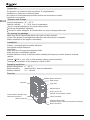
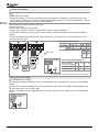
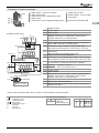
Overview
Mains connection
Relay output
Heat sink
Type plate
Operator panel
Communication interface X21
with RJ45 connection
Memory card slot
Plug-in section for
optional communication module
Control terminals
Software version plate
(between Memory card slot and Control terminals)
Motor connection
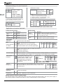
2
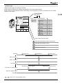
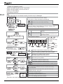
Inverter type
Determine the type of frequency inverter.
Verify that the rated input voltage corresponds to the local power supply.
Verify that the recommended motor shaft power of the frequency inverter corresponds to the rated
power of the motor.
Type designation
AGL 402-05
47807 Krefeld
Germany
Rated
input voltage
402 400 V
Frequency Inverter AGL402 18 2 FA
Input 400 V / 480 V 50 - 60 Hz
3ph 12.8 A
Output 0 - Uinput, 0 - 1kHz, 3ph
4.0 kW Cont. 60s 1s
9.5A 14.2A 19.0A
Power Conversion
Equipment
Item Code:
Integrated Filter / IP20
Ratings for temp. rang e 0 - 40°C
Refer to Instruction Manual
SI AGL1 2 3 4 5 6 7 8 9
PART No.:
Serial No.:
AGL4 0 2 0 7 1 FA- 0 0 0 0 0 0 0
9100512345
Made in Germany
GB
Recommended
motor shaft power Frame size
02 0.25 kW
1
03 0.37 kW
1
05 0.55 kW
1
1
07 0.75 kW
1
09 1.1 kW
1
11 1.5 kW
1
13 2.2 kW
2
15 3.0 kW
2
18 4.0 kW
3
19 5.5 kW
3
21 7.5 kW
3
22 9.2 kW
3
23 11.0 kW
Part number & Serial number
Warning! Electrostatic sensitive components.
Warning! High leakage current.
Warning! Dangerous voltage. Risk of electric shock.
Warning! Hot surfaces.
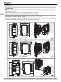
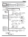
Assembly
A1 Frame size 1
A2 Frame size 2
Mains connection
B
Motor connection
C
Commissioning
D
A3 Frame size 3
Operating via control signals.
Operating via operator panel.
D1
D2
Connection of control lines
Setup via operator panel
E
Start drive
A1 ... E : Refer to the corresponding section.
3
A
!
GB
Assembly
Assembly
Warning!
A
Warning!
Make!sure,
that no foreign particles (e.g. dust, metal shavings, wires, screws, tools) can get inside
the frequency
Make sure, inverter.
that no foreign particles (e.g. dust, metal shavings, wires, screws, tools) can get inside
frequency
inverter on a nonflammable mounting plate.
Install
thethe
frequency
inverter.
Installation
in frequency
bottom-upinverter
or horizontal
position is not
permissible.
Install the
on a nonflammable
mounting
plate.
Installation in bottom-up or horizontal position is not permissible.
Screw the frequency inverter to a metallic (not varnished) mounting plate.
the frequency
inverter
a metallic (not varnished) mounting plate.
The Screw
frequency
inverter must
betoearthed.
The frequency
inverter must
be earthed.
For potential
equalization
connect
frequency inverters, cabinets, machine frames, filters etc. via short
For
potential
equalization
connect
inverters,
machine frames, filters etc. via short
conductors (with large cross-section)frequency
to the same
earthcabinets,
potential.
conductors (with large cross-section) to the same earth potential.
170
170
120
120
60 60
244244
200200
220
220
(+3
(+3
) )
30
A1
30
80
A1
Frame size 1
Frame size 1
kg 1.1
kg 1.1
196
80
196
138
138
220
250 200
(+3)
220
250 200
(+3)
A2
40
40
125
90
A2
Frame size 2
Frame size 2
kg 2.2
205
138
125
90
250 200
kg 2.2
205
138
220
(+3)
250 200
220
(+3)
A3
4
A3
Frame size 3
Frame size 3
kg 3
kg 3
Assembly
A
Installation spacing
d
d > 100 mm
GB
d
Mains connection
B
Danger!
!
Switch off power supply.
Dangerous voltage: The power terminals may carry dangerous voltages for some time even if the
power supply is switched off. Wait for some minutes before starting to work at the frequency inverter.
Make sure that the frequency inverter is de-energized.
Do not carry out high voltage insulation tests on cables connected to the frequency inverter.
Follow local wiring codes.
Connect mains supply.
!
F1
B
PE
L3
L2
L1
3
400 V
0.5 Nm
F1
L1, N
PE
or
9.2 11
35 35
4
2x4
1 x 10
kW 0.25 ... 1.5 2.2 3.0 4.0 5.5 7.5
6
10 10 10 25 25
A
2
mm
1.5
2.5
2
mm
2 x 2.5
2 x 1.5
1 x 10
1 x 10
2
mm
1.5
2.5
4
10
F1
F1
AWG
16
14
12
8
Note:
: Only required for DC-link connections.
X1
Connection on IT mains configuration
For connection on IT mains configuration remove the IT-jumper.
Note:
The removal of the IT-jumper reduces the noise immunity. The noise
immunity can be improved by external filters.
5
Motor connection
C
!
Danger!
Switch off power supply.
Dangerous voltage: The power terminals may carry dangerous voltages for some time even if the
power supply is switched off. Wait for several minutes before starting to work on the frequency inverter.
Make sure that the frequency inverter is de-energized.
Ground the motor-side grounding terminal.
Connect the motor.
Cables must be as short as possible.
Comply with the data of the motor type plate for star or delta connection.
Connect the conductor shielding of the motor cable to ground potential by means of the shielding
clamp.
Connect the conductor shielding to ground potential on both sides (near to the frequency inverter
and near to the motor).
GB
Conductor cross-section
C
X2
X2
U V W
Rb1 Rb2
U V W
U, V, W
PE
or
Rb1 Rb2
kW 0.25 ... 4.0 5.5 7.5 9.2 11
mm2
1.5
2.5
4
2
mm
2 x 2.5 2 x 4
2 x 1.5
1 x 10 1 x 10
1 x 10
2
mm
1.5
2.5
4
10
0.5 Nm
U VW
U VW
Motor cable shielding
M
3
AWG
16
14
12
8
M
3
Max. motor cable length [m]
_ 1.5 2.2 ... 11
Recommended
kW <
motor shaft power
unshielded cable
shielded cable
50
25
100
50
Rb1, Rb2: Only required for braking resistor connection.
Wiring of control cables
Use shielded control cables.
Connect the conductor shielding of the control cables to ground potential by means of the shielding
clamp.
Connect the conductor shielding to ground potential on both sides of the cable. Analog cables must
be grounded only on the inverter side.
The control cables must be separated from the motor cable and mains cable (not in the same cable
duct).
Control cable
shielding
6
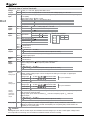
D
Commissioning
Before putting the frequency inverter into operation all covers of the device must be assembled.
!
Warning!
Switch off power supply before connecting or disconnecting terminals.
A
B C
Assembly
GB
Electrical connection of mains and motor
Operating via control signals
Operating via operator panel
D1 Connect
D2 Connect switch for enable signal
- switch for enable signal
- switches for drive-starting and reversal of rotation
- potentiometer for speed control
E
Setup via control signal. Refer to section “Setup
via operator panel”.
Start drive via control signals.
X13
Setup via operator panel. Refer to
section “Setup via operator panel”.
Start drive via key of operator panel.
X13
X12
X11
D2
GND
STOB
10 VDC
D1
E
!
X12
STOB
0..10V
2 3 4
2
1.5 mm
max. 2.5 mm2
X13
3
Enable
Start
X11
3 4 5
Start drive via control signals
After Setup switch on start signals on X11.4 (start
clockwise) or X11.5 (start anticlockwise).
The drive is accelerated to 3.50 Hz (default value
of P418).
Note: STOA & STOB must be enabled.
X12
Enable
X11
STOA
STOA
Start clockwise
Start anticlockwise
1
Speed
24 VDC out
24 VDC out
3
1
3
Start drive via key of operator panel
After Setup select function Motorpoti (menu
/
, refer to section “Menus and
functions”).
Press RUN.
The drive is accelerated to 3.50 Hz (default
value of P418).
Press the arrow keys to vary the speed.
Note: STOA & STOB must be enabled.
In case of errors refer to section “Error messages and warnings”.
In case of wrong direction of rotation exchange two motor phases (e.g. U and V).
Note
For the default functions of all control terminals refer to section “Functions of control terminals”.
7
E
Setup via operator panel
Switch on enable signals on X11.3 and X13.3.
Switch off start signals on X11.4 and X11.5.
Switch on mains supply.
Start Setup procedure.
! Caution!
GB
If the motor data is not entered correctly, the drive may be damaged.
RUN
ESC
Setup can be selected via menu item “Setup”.
At first switch-on Setup is displayed automatically.
ENT
STOP
Select for the first commissioning.
Select for only motor data measuring.
Select for commissioning of communication.
ENT
ENT
ENT
Complete Setup
Data set selection
ENT
Only motor data
Control method
Asynchronous motor V/f-control with variable speed
(default).
Asynchronous motor Field-oriented control. High drive
Synchronous motor dynamics and accurate speed control
and torque control.
ENT
Communication
ENT
ENT
Motor typeplate (example)
Control
method
-1
V
Hz kW A
min cos
230/400 50 0.25 1.32-0.76 1375 0.77
ENT
ENT
Rated power
from motor
typeplate in kW
Auto-tuning
Automatic measurement of further motor data.
Select if the data of a BONFIGLIOLI motor has been
entered. Presetting of further motor data is loaded.
ready
if Motor
has been selected.
Message only if enable signal is missing.
Set enable signals at X11.3 and X13.3.
In case of error messages refer to section “Error messages
and warnings during Setup”.
Auto-tuning
completed
Enter similarly:
ENT
5.00 Hz/s
Acceleration
(clockwise)
Deceleration
(clockwise)
Enter similarly:
ENT
ENT
Minimum
frequency
.
Entry of
(number
of pole pairs) in control
.
method
ENT
BONFIGLIOLI motor
ENT
3.50 Hz
Maximum
frequency
ENT
Setup completed and Drive enabled
initialization.
Optional
further
settings
Acceleration clockwise. Default 5 Hz/s.
Deceleration clockwise. Default 5 Hz/s.
Minimum frequency. Default 3.50 Hz.
Maximum frequency for speed limitation. Default 50.00 Hz.
Optional further settings
Motor temperature evaluation at X12.4 via thermal contact,
PTC, KTY, PT1000.
Stopping behaviour. Free coast-down, stop and switch off,
emergeny stop etc. can be set.
Functions for energy savings.
PID controller for process control.
Electronic gear. Synchronisation of drives.
Refer to the operating instructions manual.
Start drive via control signals or via key of operator panel. Refer to previous page.
8
in
and
0.25 kW
ENT
Switch on
Enable
Press
or
for 1 s
to increment or
decrement each digit
separately.
Entry of
control method
Motor
Rated voltage
0.25 kW
Enter the other rated motor
values similarly:
current (Ampere), speed,
cosine phi, poles, frequency.
Data set query is only displayed if Setup is manually selected via the
menu item “Setup”. Choose data set 0. Another setting is only
necessary for setup of various motors.
Keys
RUN
ESC
Increase speed in mode “Motorpoti”.
Scroll up to parameter numbers.
Increase parameter values.
RUN
Start the drive.
STOP
Stop the drive.
ESC
Cancel. Return to the previous menu.
ENT
Reversal of rotation in mode
“Motorpoti”. Confirm settings.
STOP
ENT
Decrease speed in mode “Motorpoti”.
Scroll down to parameter numbers.
Decrease parameter values.
GB
GB
Menus and functions
Motor stopped,
drive enabled
Motor stopped,
drive not enabled
ENT
ENT
ENT displays actual value
Actual values
: readable Parameter (actual value)
P211 is displayed first.
Warning message
ENT
Standard
Para
Access to all parameters.
Press
or
for
1 s to increment or
decrement each digit
separately.
Professional
ENT
Parameter settings
ENT
Acceleration (cw)
5.00 Hz/s
Easy
P28 is displayed first.
Speed
Increase
Most commonly used
parameters.
ENT
ENT
Motorpoti,
set frequency
Manual control
Quick commissioning
parameters.
Switch on Enable
on X11.3 and
X13.3.
Switch off start
commands on
X11.4 and X11.5.
ENT
Field-oriented control of
asynchronous motor.
Refer to operating manual.
Refer to operating manual.
ENT
Parameter copy.
Memory card
required.
ENT
Complete Setup
Decrease
STOP Stop drive
Invert reference
ENT
value
Set Jog frequency via
P489. Default: 5 Hz.
ENT
Data set
V/f-control of
asynchronous motor.
Percentage value
Increase
..
.
Only motor data
ENT
STOP Stop drive
Reversal of
ENT
rotation
Stop drive
RUN
RUN
Start drive with
JOG-speed
Communication
Decrease
3.50 Hz
Start drive Reference
Default value
frequency
of P418.
RUN
ENT
RUN
Motorpoti,
0.00%
Start drive Reference
Default value
set reference
percentage
of P518.
percentage
value
value
Jog mode
Field-oriented control of
synchronous motor.
RUN
Control method
ENT
..
.
ENT
ENT
Control method
and motor type
Progress of
parameter copy
ENT
Motor data
Refer to
operating
manual.
Select file
STOP
Acknowledge
Error message
ESC
10 s
9
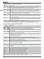
Error messages and warnings during Setup
Display
Error messages
Fault clearance
... Check rated motor values in parameters 370...376. Correct the values if necessary. Repeat
Setup. Check motor cable connections and frequency inverter connections.
GB
Warnings
... Check rated motor values in parameters 370...376. Correct the values if necessary. Repeat
Setup.
, The following causes are possible: The motor cable cross-section is not sufficient. The motor
cable is too long. The motor cable is not connected correctly.
, Check P372 (rated speed), P375 (rated frequency).
The machine data for star connection is entered, but the motor is connected in delta. For star
connection change the motor cable connection. For delta connection check the entered rated
motor values. Repeat Setup.
The machine data for delta connection is entered, but the motor is connected in star. For delta
connection change the motor cable connection. For star connection check the entered rated
motor values. Repeat Setup.
Check motor connection and frequency inverter connections.
Press ESC to correct a parameter value after an error message or after a warning message.
Press ENT to ignore a warning message. Setup is coninued. It is recommended to check the entered data.
Error messages and warnings during operation
Display
Error messages
Fault clearance
, ...
Frequency inverter overloaded. Check load behavior. Check motor parameter settings.
Overtemperature. Check cooling, fan, sensor and ambient temperature.
Low temperature. Check ambient temperature and electrical cabinet heating.
, Motor temperature too high or sensor defective. Check connection on X12.4. Phase failure. Check
motor and wiring.
... Overloaded, short circuit or earth fault, motor current or phase failure. Check load behavior and
ramps (P420...P423). Check motor and wiring.
... DC link voltage too high or too low. Check deceleration ramps (P421, P423) and the connected
brake resistor. Check mains voltage.
Power failure or phase failure, voltage break-chopper or motor-chopper too high. Check mains
voltage, mains fuses and circuit.
Electronics voltage (24 V) too high or too low. Check wiring of control terminals.
, ... Maximum frequency achieved. Check control signals and settings. Check deceleration ramps
(P421, P423) and the connected brake resistor.
Minimum output current. Check motor and wiring.
Reference value signal on input X12.3 faulty, check signal.
Overcurrent on input X12.3, check signal.
Overcurrent on input X12.4, check signal.
Warnings
... Frequency inverter overloaded. Check load behavior. Check motor parameters and application
parameters.
, Overtemperature. Check cooling, fan and ambient temperature.
Max. motor temperature reached, check motor and sensor.
Mains phase failure, check mains fuses and supply cable.
Limit frequency reached; output frequency is limited.
Input signal at X12.3 is too low. Increase the value.
Input signal at X12.4 is too low. Increase the value.
DC link voltage has reached the type-specific minimum.
Press ESC to hide an error message. It it displayed again after 10 seconds.
Press STOP to acknowledge an error message or a warning message. Remove the fault.
10
Functions of control terminals
digital inputs, 2 of them for Enable
digital input/output
2 multifunction inputs: digital/analog input
1 digital output
1 multifunction output: digital/analog/frequency
X10
X13
X12
X11
6
1
1
2
voltage input 24 VDC
voltage outputs, 10 and 24 VDC
1 relay output
Communication
interface CAN
GB
T
X13.1
X13.2
X13.3
OUT1D
MFO1
10V out
X13
24V in
GND
STOB
Standard control wiring
X13.4
X13.5
1 2 3 4 5 6
+
Reference speed
X13.6
V
CAN H
CAN L
X12
Digital inputs
IN4D
IN5D
MFI1
MFI2
Actual speed
1 2 3 4 5 6
IN3D
1 2 3 4 5 6
+24 V
Relay output OUT2D
321
X10
Fault message
2
0.1 ... 1.5 mm
30 ... 14 AWG
(OUT3D)
IN2D
STOA
IN1D
X11
GND
Digital inputs
24Vout
°C
M
Enable
24 VDC
Default function
24 VDC input
GND for X13.1
Digital input. Input 2 for enable. Contact opened: output
disabled, motor coast to a standstill. Contact closed
(together with X11.3): normal operation.
10 VDC output
Digital output. Run signal. Indicates output of frequency
when enable and start command applies.
Multifunction output. Default: analog. Voltage signal
proportional to actual speed. 10 V at 50 Hz, 0 V at 0 Hz.
X12.1 Digital input.
Data set change-over together with X11.6.
X12.2 Digital input. Error acknowledgment.
X12.3 Multifunction input: digital/analog. Default: analog voltage
input. Reference speed. 50 Hz at 10 VDC, 3.50 Hz at 0 VDC.
X12.4 Multifunction input: digital/analog. Default: digital input.
For connection of motor thermal contact. Set P570.
X12.5 CAN High Systembus connection.
Refer to the separate manual.
X12.6 CAN Low
X11.1 24 VDC output
X11.2 GND for X11.1
X11.3 Digital input. Input 1 for enable. Contact opened: output
disabled, motor coast to a standstill. Contact closed
(together with X13.3): normal operation.
X11.4 Digital input. Start clockwise.
X11.5 Digital input. Start anticlockwise.
X11.6 Digital input/output. Default: input. Data set change-over
together with X12.1.
Comply with the technical data. Refer to section “Technical data of control terminals”.
IN D:
MFI1:
MFI2:
OUT D:
MFO1:
P:
T:
X:
digital input
multifunction input
multifunction input
digital output
multifunction output
Parameter
Terminal
Terminal strip
Thermal contact evaluation
X12.4 P570 0-off (default)
1-Warning
2-Error switch-off
Data set change-over
X11.6 X12.1 Selection
0
0 Data set 1
1
0 Data set 2
1
1 Data set 3
0
1 Data set 4
11
Extended settings of control terminals
Multifunction input
X12.3 P452 1-voltage 0...10V
X12.4 P562 2-current 0...20mA
3-digital NPN
4-digital PNP
5-current 4...20mA
6-voltage, characteristic
7-current, characteristic
GB
Multifunction output
X13.6 P550 1-digital
2-analog (default)
3-repetition frequency
4-pulse train
P554
Select
P553
signal.
P555
P557 Scaling.
Default:
1-: Signal when output frequency exceeds 3 Hz (P510).
2-: Output of voltage proportional to speed.
3-: Frequency output. 0...24 V propotional to speed.
4-: Output of pulse train, scaled by P557.
6-: programmable characteristic via P454...457
7-: programmable characteristic via P564...567
(Refer to operating instructions manual.)
Switchable logic of digital inputs
X11.4 P559 0-NPN X12.3 P452
1-PNP
X11.5
X11.6
X12.4 P562
X12.1
X12.2
Digital input/output
X11.6 P558 0-input (default)
1-output
3-digital
4-digital
3-digital
4-digital
input
input
input
input
NPN
PNP
NPN
PNP
NPN: LOW-switching (on negative signal). Default of P562.
PNP: HIGH-switching (on positive signal). Default of P559.
Applications via control terminals
Voltage input and outputs
Function
T
Voltage input
GND
Voltage output
GND
Voltage output
X13.1
X13.2
X11.1
X11.2
X13.4 10 VDC
Input signals
Application
T
Start
X11.3
X13.3
Change direction X11.4
X11.5
of rotation
Stop
24 VDC
GND for terminal X13.1
24 VDC
GND for terminal X11.1
X11.3
X13.3
X11.4
X11.5
Output signals
T
Actual
frequency
Function
X13.6 Voltage signal proportional to frequency
(speed). At 50 Hz (P419) output of 10 VDC.
At 0 Hz output of 0 VDC.
Operational X13.5 Run signal. Indicates enable and start
state
command. Output frequency available.
Default function and settings
Enable: digital signals at both terminals.
AND
Start clockwise (cw) via rising signal edge or
Start anticlockwise (ccw) via rising signal edge.
X11.3 X13.3 X11.4 X11.5
1
0
1
0
Enable
Start cw
1
1
1
0
1
0
1
1
Start ccw
1
1
1
1
Stop
Disable: Reset digital signal on at least one terminal.
OR
Reset Start clockwise or
Reset Start anticlockwise.
Set motor speed X12.3 Reference speed 0 ... 10 VDC at analog input. P452=1-voltage (default). 0 V corresponds
to 3.50 Hz (default value of P418). 10 V corresponds to 50 Hz (default value of P419).
Fixed frequency change-over via
two digital inputs. Set P492=3. Set
frequency values in P480 ... 483.
Select digital inputs for P66 and
P67. Select a frequency value via
P66 and P67.
Digital inputs
P66 P67 Selection Default
71 X11.4
0 0
P480
0 Hz
72 X11.5
1 0
P481 10 Hz
73 X11.6 (P558=0)
1 1
P482 25 Hz
74 X12.1
0 1
P483 50 Hz
75 X12.2
76 X12.3 (P452=3 NPN or 4 PNP)
77 X12.4 (P562=3 NPN or 4 PNP)
Select output
frequency
X
X
Data set
change-over
X11.6 Data set change-over via two digital inputs. The four data sets
X12.1 can include different parameter values. Select a data set via
X11.6 and X12.1.
Protection function
Application
T
Motor
temperature
X11.6 X12.1 Selection
0
0 Data set 1
1
0 Data set 2
1
1 Data set 3
0
1 Data set 4
Function and settings
X12.4 Connect a motor thermal contact.
Set P570: 1 Warning or 2 Error switch-off.
Voltage input for external voltage supply
The external voltage supply enables the function of inputs, outputs and communication, even if the power supply of
the frequency inverter is switched off. Refer to section “Technical data of control terminals”.
12
Data set
Parameter values can be stored in four different data sets.
If a data set is selected, the entered data is only stored in the selected data set. The other data sets
contain standard values. If no data set is selected the entered data is stored in all four data sets.
The data sets can be switched-over via control terminals (refer to section “Functions of control
terminals”). This enables the setting of different operating points of the drive or settings for different
motors.
Example 1: Carry out auto-tuning and enter motor data in data set 1.
GB
GB
..
.
ENT
ENT
Data set
When setup is carried out the entered and measured motor data is stored in the selected data set.
Example 2: Set the motor rated voltage P370 in data set 2.
ENT
ENT
ENT +
Hold
Value of P370 in data set 2
Data set
Display actual values
Parameter Display
R.m.s. output current of the frequency inverter (motor current).
R.m.s Current [A]
P211
Output Voltage [V]
Output voltage of the frequency inverter.
P212
Power of the motor at the current operating point.
Active Power [kW]
P213
-1
Actual Speed [min ] P240
Motor speed.
Output frequency of the inverter (actual frequency of the motor).
Actual Frequency [Hz] P241
P259
The cause of error switch-off.
Current Error
Warnings
Warning because of a critical condition.
P269
Last Error
P310
The last error.
Optional communication modules
RS485, Modbus or VABus:
RS232, Modbus or VABus:
Profibus-DP:
CANopen or System bus:
CM-485
CM-232
CM-PDPV1
CM-CAN
CM
X21
Communication interface X21 with RJ45 connection
For serial RS485 communication via VABus or Modbus protocol.
BONFIGLIOLI Vectron provides an interface adaptor for the USB connection of a PC. This enables
parametrization and monitoring via the PC software VPlus.
Parameter copy
Parameter values can be stored on a memory card ("Resource Pack") and transferred from one inverter
to another inverter.
Reset to factory setting
Select P34 in menu item
values.
. Set P34 to 4444. This resets the parameter settings to the default
Key lock
Select P27 in menu item
and set a password. Then parameter values in menu item
and
the motorpoti function are password-protected. Ten minutes after a correct password entry the
password inquiry is displayed again.
Further information
Detailled operating instructions can be downloaded from the website of BONFIGLIOLI.
13
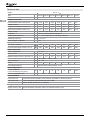
Technical data
400 V 3
AgilE 1
402-02 402-03 402-05 402-07 402-09 402-11
Type
1
Size
GB
402-13
Output, motor side
kW
0.25
0.37
0.55
0.75
1.1
1.5
2.2
Output current
A
0.8
1.2
1.5
2.1
3.0
4.0
5.5
Long-term overload current (60 s)
A
1.2
1.8
2.25
3.15
4.5
6.0
8.2
Short-term overload current (1 s)
A
1.6
2.4
3.0
4.2
6.0
8.0
11.0
Output voltage
V
Recommended motor shaft power
3-phase. Input voltage as max. output value.
Short-circuit proof/earth fault proof
Protection
Rotating field frequency
Hz
0 ... 1000, depending on switching frequency
Switching frequency
kHz
2, 4, 8, 16
Yes
Brake-chopper integrated
Output, brake resistor
Min. brake resistance
300
300
300
300
300
220
220
Recommended brake resistor (770 V)
2432
1594
930
634
462
300
220
Input, mains side
Mains configuration
TT, TN, IT
Rated current
A
0.8
1.2
1.8
2.4
2.8
3.3
5.8
Maximum mains current (EN 61800-5-1)
A
1.1
1.5
2.0
2.7
3.9
5.2
7.3
Mains voltage range
V
380 (-15%) ... 480 (+10%)
Mains frequency
Hz
45 ... 69
Fuses [UL 600 VAC RK5]
A
6 [6]
6 [6]
6 [6]
6 [6]
10 [10]
70
89
122
Overvoltage category
6 [6]
6 [6]
EN 50178 III, DIN EN 61800-5-1 III
Influencing factors
Energy dissipation
(at 2 kHz switching frequency)
W
Coolant temperature (air)
°C
Communication
Connection X21
19
29
42
53
0 ... 40 (40 ... 55 with derating)
Serial data interface RS485. Communication via VABus or Modbus protocol.
CAN system bus
Control terminals, CAN interface ISO-DIS 11898.
Optional module
RS232, RS485, Profibus-DP or CANopen.
Storage
Digital memory card
14
Save and transfer parameter values via standard memory card.
Technical data
AgilE 2, AgilE 3
400 V 3
Type
402-15 402-18
Size
2
402-19
402-21
402-22 402-23
3
Output, motor side
kW
3.0
4.0
5.5
7.5
9.2
11.0
Output current
A
7.5
9.5
13.0
17.0
20.0
23.0
Long-term overload current (60 s)
A
11.2
14.2
19.5
25.5
30.0
34.5
Short-term overload current (1 s)
A
15.0
19.0
26.0
34.0
38.0
46.0
Output voltage
V
Recommended motor shaft power
GB
3-phase. Input voltage as max. output value.
Short-circuit proof/earth fault proof
Protection
Rotating field frequency
Hz 0 ... 1000, depending on switching frequency
Switching frequency
kHz 2, 4, 8, 16
Yes
Brake chopper integrated
Output, brake resistor
Min. brake resistance
106
106
48
48
48
48
Recommended brake resistor (770 V)
148
106
80
58
48
48
Input, mains side
Mains configuration
TT, TN, IT
Rated current
A
6.8
7.8
14.2
15.8
20.0
26.0
Maximum mains current (EN 61800-5-1)
A
9.8
12.8
17.2
23.0
28.1
33.6
Mains voltage range
V
Mains frequency
Hz 45 ... 69
A 10 [10] 10 [10] 25 [20] 25 [20] 35 [30]
Fuses [UL type 600 VAC RK5]
Overvoltage category
380 (-15%) ... 480 (+10%)
35 [40]
EN 50178 III, DIN EN 61800-5-1 III
Influencing factors
Energy dissipation
(at 2 kHz switching frequency)
W
Coolant temperature (air)
°C 0 ... 40 (40 ... 55 with derating)
Communication
Connection X21
133
167
235
321
393
470
Serial data interface. RS485 communication via VABus or Modbus protocol.
CAN system bus
Control terminals, CAN interface ISO-DIS 11898.
Optional module
RS232, RS485, Profibus-DP or CANopen.
Storage
Digital memory card
Save and transfer parameter values via standard memory card.
15
Technical data of control terminals
Voltage
outputs
X11.1 24 VDC, Imax=100 mA. Appropriate GND: X11.2.
Voltage
input
X13.1 Input for external voltage supply. Connect the ground potential of the external voltage supply to
X13.2 (GND).
Input voltage range 24 VDC ±10%
Rated input current Max. 1.0 A (typical 0.45 A)
Peak inrush current Typical < 15 A (max. 100 µs)
External fuse
Via standard fuse element for rated current, characteristic: slow
Safety
Safety extra low voltage (SELV) according to EN 61800-5-1
Digital
enable
inputs
X11.3 Signal levels
X13.3 Umax
Input resistance
Response time
Digital
inputs
X11.4
PNP input High 10 VDC
Signal levels
X11.5
NPN input High 5 VDC
X12.1 Umax
30 VDC (6 mA at 24 VDC)
X12.2 Input resistance 3.9
Response time 2 ms
PLC-compatible
Digital input/output
X11.6
Multifunction
X12.3
Multifunction
X12.4
Digital
outputs
X13.5 Uout 22 VDC (15 ... 30 VDC)
Imax 100 mA (Imax is reduced if further control outputs are used.)
Overload- and short-circuit-proof, overvoltage-protected.
Digital input/output
X11.6
Analog
input
Multifunction
X12.3
Multifunction
X12.4
Refer to table row “Digital inputs”.
X11.6 Default: digital input.
Can be configured as digital output by means of P558.
Output:
Uout 22 VDC (15 ... 30 VDC)
Imax 100 mA (Imax is reduced if further control outputs are used.)
Overload- and short-circuit-proof, overvoltage-protected.
GB
Digital
input/
output
X13.4 10 VDC, Imin=2.3 mA (dependent on level of 24 VDC voltage input), Imax=8.2 mA
Low 0 ... 3 VDC, High 12 ... 30 VDC
30 VDC (10 mA at 24 VDC)
1.8
STO is activated 10 ms after triggering.
Switch-over PNP/NPN
X11.4 P559 X12.3 P452
X11.5
X12.4 P562
X12.1
X12.2
X11.6
Multifunction
Digital/
X12.3 Default: analog voltage input. Can be configured as analog current input or digital input
analog input
by means of P452.
Voltage input 0 ... 10 VDC
Current input 0 ... 20 mA
Digital input
Digital/
analog input
Resolution 10 Bit
Resolution 9 Bit
Ri: input resistance
Refer to table row “Digital inputs”.
X12.4 Default: digital. Can be configured as analog input MFI2A by means of P562.
Resolution 10 Bit
Voltage input 0 ... 10 VDC
Ri: input resistance
Resolution 9 Bit
Current input 0 ... 20 mA
Refer to table row “Digital inputs”.
Digital input
X13.6 Default: analog. Can be configured as digital output, analog output, frequency output or pulse
train output by means of P550.
Analog signal: pulse width modulated, fpwm=116 Hz. Frequency signal: fmax=150 kHz.
Digital output:
Uout 22 VDC (15 ... 30 VDC)
Imax 100 mA (Imax is reduced if further control outputs are used.)
Overload- and short-circuit-proof, overvoltage-protected.
Relay output X10 Floating change-over contact. Response time approx. 40 ms, suitable for brake control.
Maximum contact load: make contact: AC 5A/240V, DC 5A (ohmic)/24V, break contact: AC
3A/240V, DC 1A (ohmic)/24V
Digital/
analog/
frequency/
pulse train
output
!
Caution!
The digital inputs and the 24 VDC input can withstand external voltage up to 30 VDC. Avoid higher voltage levels.
The temperature monitoring must be sufficient insulated towards the motor winding.
16
Bonfiglioli has been designing and developing innovative
and reliable power transmission and control solutions
for industry, mobile machinery and renewable energy
applications since 1956.
www.bonfiglioli.com
Bonfiglioli Riduttori S.p.A.
Via Giovanni XXIII, 7/A
40012 Lippo di Calderara di Reno
Bologna, Italy
tel: +39 051 647 3111
fax: +39 051 647 3126
[email protected]
www.bonfiglioli.com
VEC 651 R0